


AMPLIFIER MANUAL
MANUEL DE L’AMPLIFICATEUR
Models: R1000.1, R500.1, R250.1
R500.4, R300.4
Features |
Caractéristiques |
• 12dB Variable Low Pass and Subsonic Crossovers (R250.1, R500.1) |
• 12 dB Passe Basse Variable et Subsonique Croisé (R250.1, R500.1) |
• 18dB Variable Low Pass and Subsonic Crossovers (R1000.1) |
• 18 dB Passe Basse Variable et Subsonique Croisé (R1000.1) |
• 12dB Variable High and Low Pass Crossovers (R300.4) |
• 12 dB Haut et Passe Basse Variable Croisé (R300.4) |
• 12dB Variable High and Low Pass Crossovers (R500.4) |
• 12 dB Haut et Passe Basse Variable Croisé (R500.4) |
• High Level Input with Signal Sensing Turn-on for Easy OEM integration |
• Le Niveau Supérieur entre pour l’intégration de FABRICANT |
• Oversized Direct Insert Power and |
D’ORIGINE facile |
Speaker Terminals |
• Diriger le Pouvoir d’Insertion et les Terminaux de Haut-parleur |
• Robust Unregulated Power Supply |
• Pouvoir non Régulée Robust |
• Audiophile Bi-Polar Output Transistors |
• Audiophile Transistors de Bipolaire |
• LPL44 - Low Pass Level Control Ready |
• LPL44 - La Passe basse Nivelle Prêt de Contrôle |
• RMD -Remote Monitoring Display Port |
• RMD - Entrée De L’affichage de Tension a Distance |
• Advanced Thermal and Protection Circuitry |
• Avancé Thermique et les Circuits de Protection |
© 2010 Phoenix Gold • www.phoenixgold.com
Amplifier Owner’s Manual
SPECIFICATIONS
MONOBLOCK SPECIFICATIONS
Frequency Response: |
± 1dB from 20Hz to 300Hz |
Signal to Noise Ratio: |
>110dB |
Subsonic and Low Pass Crossovers: |
12dB per octave |
Low Pass Crossover Range: |
30Hz to 300Hz |
Subsonic Crossover Range: |
10Hz to 55Hz |
Bass Boost @ 45Hz: |
0 to +18dB |
Low Level Input Range: |
200 millivolts to 8 volts |
High Level Input Range: |
400 millivolts to 12 volts |
Lowest Recommend Load: |
2 ohm |
Typical Efficiency: |
50% |
Damping Factor: |
Greater than 200 |
R250.1
Dynamic Power 14.4Vdc >1% THD |
150 x 1 @ 4 ohm |
|
250 x 1 @ 2 ohm |
RMS Power 14.4Vdc ≤ 1% THD |
85 x 1 @ 4 ohm |
|
140 x 1 @ 2 ohm |
Recommended Fuse Size: |
25A |
Power/Ground Wire Size: |
8 Gauge |
Dimensions: |
9.5” L x 9.75” W x 2.5” H |
|
242mm x 248mm x 63mm |
R500.1
Dynamic Power 14.4Vdc >1% THD |
300 x 1 @ 4 ohm |
|
500 x 1 @ 2 ohm |
RMS Power 14.4Vdc ≤ 1% THD |
220 x 1 @ 4 ohm |
|
325 x 1 @ 2 ohm |
Fuse Size: |
40A x 1 |
Power/Ground Wire Size: |
8 Gauge |
Dimensions: |
11.1” L x 9.75” W x 2.5” H |
|
282mm x 248mm x 63mm |
R1000.1 MONOBLOCK SPECIFICATIONS
Frequency Response: |
± 1dB from 20Hz to 300Hz |
Signal to Noise Ratio: |
>90dB |
Subsonic and Low Pass Crossovers: |
18dB per octave |
Low Pass Crossover Range: |
30Hz to 300Hz |
Subsonic Crossover Range: |
10Hz to 55Hz |
Bass Boost @ 45Hz: |
0 to +18dB |
Low Level Input Range: |
200 millivolts to 8 volts |
High Level Input Range: |
400 millivolts to 12 volts |
Lowest Recommend Load: |
1 ohm |
Typical Efficiency: |
80% |
Damping Factor: |
Greater than 200 |
R1000.1
Dynamic Power 14.4Vdc >1% THD |
750 x 1 @ 2 ohm |
|
1000 x 1 @ 1 ohm |
RMS Power 14.4Vdc ≤ 1% THD |
550 x 1 @ 2 ohm |
|
800 x 1 @ 1 ohm |
Fuse Size: |
40A x 2 |
Power/Ground Wire Size: |
4 Gauge |
Dimensions: |
12.7” L x 9.75” W x 2.5” H |
|
322mm x 248mm x 63mm |
FOUR CHANNEL SPECIFICATIONS
Frequency Response: |
± 1dB from 20Hz to 20kHz |
Signal to Noise Ratio: |
>110dB |
High and Low Pass Crossovers: |
12dB per Octave |
Low Pass Crossover Range: |
40Hz to 400Hz |
High Pass Crossover Range: |
40Hz to 400Hz |
Bass Boost @ 45Hz: |
0 to +18dB |
Low Level Input Range: |
200 millivolts to 8 volts |
High Level Input Range: |
400 millivolts to 12 volts |
Lowest Recommend Load: |
4 ohm Bridged or 2 ohm Stereo |
Typical Efficiency: |
50% |
Damping Factor |
Greater than 200 |
R500.4 |
|
|
R300.4 |
|
Dynamic Power 14.4Vdc >1% THD |
75 x 4 @ 4 ohm Stereo |
Dynamic Power 14.4Vdc >1% THD |
50 x 4 @ 4 ohm Stereo |
|
|
125 x 4 |
@ 2 ohm Stereo |
|
75 x 4 @ 2 ohm Stereo |
|
250 x 2 |
@ 4 ohm Bridged |
|
150 x 2 @ 4 ohm Bridged |
RMS Power 14.4Vdc ≤1% THD |
60 x 4 @ 4 ohm Stereo |
RMS Power 14.4Vdc ≤1% THD |
40 x 4 @ 4 ohm Stereo |
|
|
85 x 4 @ 2 ohm Stereo |
|
55 x 4 @ 2 ohm Stereo |
|
|
170 x 2 |
@ 4 ohm Bridged |
|
110 x 2 @ 4 ohm Bridged |
Fuse Size: |
25 amp x 2 |
Fuse Size: |
40 amp x 1 |
|
Power/Ground Wire Size: |
8 Gauge |
Power/Ground Wire Size: |
8 Gauge |
|
Dimensions: |
15.0” L x 9.75” W x 2.5” H |
Dimensions: |
12.7” L x 9.75” W x 2.5” H |
|
|
382mm x 248mm x 63mm |
|
322mm x 248mm x 63mm |
|
© 2010 Phoenix Gold • www.phoenixgold.com
Amplifier Owner’s Manual
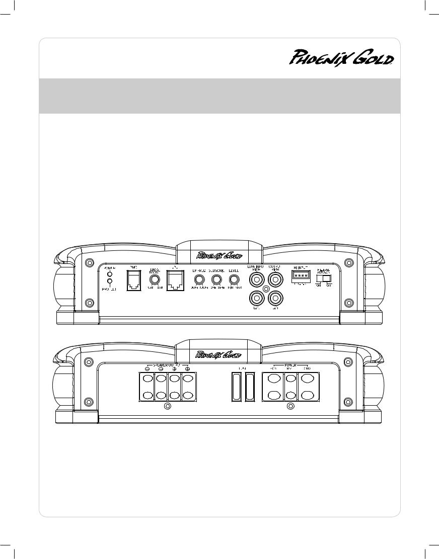
R1000.1 - R500.1 - R250.1 MONOBLOCK POWER AMPLIFIER
INPUT
Connect preamp signal cables from the head unit to these terminals.
OUTPUT
Provides a full range signal for an additional amplifier. There is no signal loss if using this output.
CROSSOVER FREQUENCY
Controls the lowpass crossover point for the speaker outputs.
BASS BOOST
Variable bass boost from 0 to +18dB @ 45 Hz.
LOW PASS LEVEL CONTROL (LPL)
This port is for connecting the optional remote level control (LPL44). This allows up to 20dB of volume adjustment. This is not a bass boost, it
controls the level of the low pass signal.
REMOTE MONITORING DISPLAY (RMD)
Connect optional RMD Voltage Display to this port
LEVEL
Used to reach maximum amplifier power with a wide variety of headunits.
HI INPUT
Connect a factory system’s headunit or amplifier outputs. Using the HI level input the amplifier will automatically turn on and off using the factory system’s audio signal as a trigger. The high level auto on switch turns off the auto turn on function, but the high level input still works as normal.
SUBSONIC CROSSOVER FREQUENCY
Controls the highpass crossover point for the speaker outputs to eliminate extreme low frequencies.
12V+ |
SPEAKER OUTPUTS |
This must be connected to the fused positive terminal (+12V) of the car’s battery. The fuse must be located within 18 inches of the battery.
REMOTE
This must be connected to switched +12V, usually a trigger wire coming from the head unit or ignition. This is not used if using Hi input auto on feature.
GND
This must be connected to the negative terminal of the car’s battery or bolted to a clean, unpainted part of the chassis of the vehicle.
Used to connect the amplifier to speakers. R250.1 and R500.1 minimum impedance is 2 ohm, R1000.1 is 1 ohm.
© 2010 Phoenix Gold • www.phoenixgold.com

Amplifier Owner’s Manual
R500.4 - R300.4
4 CHANNEL POWER AMPLIFIER
INPUT
Connect preamp signal cables from the head unit to these terminals.
HIGH LEVEL INPUT
Connect a factory system’s headunit or amplifier outputs. Using the HI level input the amplifier will automatically turn on and off using the factory system’s audio signal as a trigger. The high level auto on switch turns off the auto turn on function, but the high level input still works as normal.
OUTPUT
Provides a full range signal for an additional amplifier. There is no signal loss if using this output.
CROSSOVER FREQUENCY
Controls the crossover point for the speaker outputs.
BASS BOOST
Variable bass boost from 0 to +18dB @ 45 Hz.
2ch/4ch MODE
2ch: Headunit has one pair of cables into front Input.
4ch: Headunit has two pairs of cables into front and rear inputs.
LOW PASS LEVEL CONTROL (LPL)
This port is for connecting the optional remote level control (LPL44). This allows up to 20dB of volume adjustment. This is not a bass boost, it controls the level of the entire low pass signal of the rear channels.
REMOTE MONITORING DISPLAY (RMD)
Connect optional RMD Voltage Display to this port
LEVEL
Used to reach maximum amplifier power with a wide variety of headunits.
CONFIG
FLAT: Crossovers are turned off
HP: High pass crossover is on
LP: Low pass crossover is on
12V+ |
SPEAKER OUTPUTS |
This must be connected to the fused positive terminal (+12V) of the car’s battery. The fuse must be located within 18 inches of the battery.
REMOTE
This must be connected to switched +12V, usually a trigger wire coming from the head unit or ignition. This is not used if using Hi input auto on feature.
GND
This must be connected to the negative terminal of the car’s battery or bolted to a clean, unpainted part of the chassis of the vehicle.
Used to connect the amplifier to speakers. Use the left + and right - terminals for bridged mode. Minimum impedance is 4 ohm bridged or 2 ohm stereo.
© 2010 Phoenix Gold • www.phoenixgold.com
 Loading...