


AMPLIFIER MANUAL
MANUAL DEL AMPLIFICADOR
MANUEL DEL’AMPLIFICATEUR
Models: Ti2 1000.4, Ti2 1600.5
Features: |
Características: |
Caractéristiques: |
||
• High Efficiency Class D Topology |
• Alta eficiencia de clase D Topología |
• Petit format pour faciliter l’installation |
||
• Compact Size for Easy Installation |
• Tamaño compacto para fácil instalación |
• Topologie de classe D de gamme complète |
||
• Balanced Differential Input Circuitry |
• Diferencial balanceada circuitos de entrada |
• Circuit équilibré Entrée différentielle |
||
• Audiophile NJM2068M Operational Amplifiers |
• Audiophile NJM2068M amplificadores operacionales |
• Audiophile NJM2068M Amplificateurs opérationnels |
||
• Ultra High Speed IR Class D Chipset |
• IR Chipset Ultra Alta Velocidad |
• Haute Vitesse IR de classe D chipset |
||
• High, Band and Low Pass Crossovers |
• Crossovers paso alto y bajo |
• Filtres croisés passe-haut et passe-bas |
||
• ADAPT Power Management System |
• ADAPT Sistema de Gestión de Energía |
• |
ADAPT système d’alimentation |
|
• Surface Mount Component Technology |
• Tecnología “Surface Mount Component” |
• Technologie de composant monté en surface |
||
• Direct Insert Power and Speaker Terminals |
• Conexiones directas de terminales de poder y de |
• Terminaux d’alimentation et de haut-parleurs à |
||
• Audio Precision Quality Control Verification |
parlantes |
|
insertion directe |
|
• |
High Temperature Plexiglass cover |
• Control de verificación de calidad de precisión de audio |
• Vérification du contrôle de la qualité de la précision audio |
|
• |
Signal Clipping Indicators |
• Cubierta de Plexiglás resistente a altas temperaturas |
• Couvercle de plexiglas résistant aux températures élevées |
|
• RMD - Remote Monitoring Display Port |
• RMD - Puerto de display para monitoreo remoto |
• RMD - Entrée De L’affichage de Tension a Distance |
||
• RBCFRemote Subwoofer Level Control included |
• RBCF - Control de nivel de Subwoofer remoto incluido |
• |
RBCFNiveau de contrôle de passe-bas inclus (Ti2 1600.5) |
|
|
(Ti2 1600.5) |
(Ti2 1600.5) |
|
|

Amplifier Owner’s Manual
SPECIFICATIONS
Ti2 1000.4 SPECIFICATIONS
Frequency Response: |
± 1dB from 20Hz to 20kHz |
RMS Power Output |
150w x 4 @ 4 ohms Stereo |
Signal to Noise Ratio: |
>100dB |
|
250w x 4 @ 2 ohms Stereo |
Crossover Slopes: |
12dB per Octave |
|
500w x 2 @ 4 ohms Bridged |
Front High/Low Pass Crossover Range: |
45Hz to 4kHz |
|
|
Rear High Pass Crossover Range: |
20Hz to 4kHz |
Power/Ground Wire Size: |
4 Gauge |
Rear Low Pass Crossover Range: |
40Hz to 4kHz |
Recommend Power Wire Fuse: |
80a |
Low Level Input Range: |
200 millivolts to 8 volts |
Dimensions: |
11.7” L x 7.1”W x 2.0” H |
Lowest Recommend Load: |
4 ohms Bridged/2 ohms Stereo |
|
296mm L x 180mm W x 52mm H |
Typical Efficiency: |
80% |
|
|
Damping Factor |
Greater than 200 |
|
|
Ti2 1600.5 SPECIFICATIONS
FRONT AND REAR CHANNELS: |
|
Frequency Response: |
± 1dB from 20Hz to 20kHz |
Signal to Noise Ratio: |
>100dB |
Crossover Slopes: |
12dB per Octave |
Front High Pass Crossover Range: |
20Hz to 4kHz |
Rear High Pass Crossover Range: |
20Hz to 4kHz |
Rear Low Pass Crossover Range: |
40Hz to 4kHz |
Low Level Input Range: |
200 millivolts to 8 volts |
Lowest Recommend Load: |
4 ohms Bridged/2 ohms Stereo |
Typical Efficiency: |
80% |
Damping Factor |
Greater than 200 |
SUBWOOFER CHANNEL: |
|
Frequency Response: |
± 1dB from 20Hz to 300Hz |
Signal to Noise Ratio: |
>100dB |
Crossover Slopes: |
12dB per Octave |
Low Pass Crossover Range: |
20Hz to 300Hz |
Subsonic Crossover Range: |
10Hz to 50Hz |
Variable Phase: |
0 to 180 degrees |
Low Level Input Range: |
200 millivolts to 8 volts |
Lowest Recommend Load: |
2 ohms |
Typical Efficiency: |
80% |
Damping Factor: |
Greater than 200 |
RMS Power Output |
125w x 4 |
@ 4 ohms Stereo |
|
200w x 4 |
@ 2 ohms Stereo |
|
400w x 2 |
@ 4 ohms Bridged |
RMS Power Output |
500w x 1 @ 4 ohms |
|
800w x 1 @ 2 ohms |
Recommend Power Wire Fuse: |
100a |
Power/Ground Wire Size: |
4 Gauge |
Dimensions: |
14.4” L x 7.1”W x 2.0” H |
|
366mm L x 180mm W x 52mm H |
POWER OUTPUT NOTE: A power birth certificate is included for each amplifier. Ti2 amplifiers are conservatively rated and will exceed their RMS power rating shown here. All RMS power ratings and measurements are at 14.4 volts with no more than 1% THD. Ti2 1000.4 and Ti2 1600.5 feature ADAPT technology which provides the same power output from 11 to 15 volts with music material.
www.phoenixgold.com
Amplifier Owner’s Manual
KEY FEATURES
A |
BALANCED DIFFERENTIAL INPUTS |
Provides maximum rejection of unwanted noise from upstream |
|
|
components. |
B |
AUDIOPHILE NJM2068M OP-AMPS |
Most mobile amplifiers today use the standard NJM4558 op-amp which |
|
|
has a bandwidth of 3MHz, slew rate of 1V/uSec and noise level of 1.4uV. |
|
The NJM2068M is simply a better performer with a bandwidth of 19MHz, |
|
slew rate of 6V/uSec and noise level of .44uV. |
|
The result is quieter, faster and wider bandwidth performance that |
|
ensures the original music material is reproduced as accurately as |
|
possible. |
C |
ULTRA HIGH SPEED IR CLASS D CHIPSET |
State of the art IR20957 chipset switches at more than 300kHz |
|
|
for blistering audio performance. All four or five chipsets are |
|
sync’d together in unison to eliminate unwanted harmonics or |
|
distortion. |
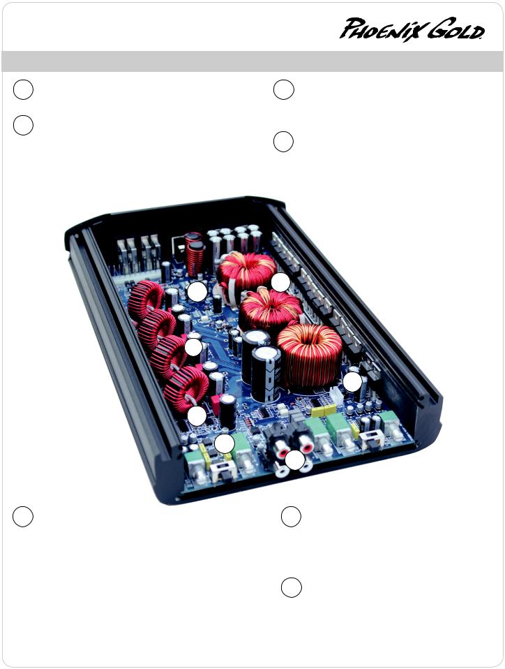
D POST FILTER FEEDBACK
Feedback is when part of the output signal is “fed back” into the original signal to ensure stability and accurate sound. Class D amplifiers use output filters (see the 4 vertical coils below), but most DO NOT INCLUDE these filters in the feedback loop. Ti2 amplifiers INCLUDE or take feedback after its passed through these filters. The result is more accurate sound that rivals some of the best class A/B amplifiers.
G E
D
C
B
E |
ADAPT POWER MANAGEMENT SYSTEM |
|
Full power output from 11 to 15 volts: ADAPT delivers the same output |
|
power regardless of the vehicle’s electrical system voltage. Instantaneous or |
|
long term voltage drops have no effect on the amplifier’s power output. This |
|
means more dynamic and less distorted audio output. |
|
Dual power modes provide maximum efficiency: ADAPT seamlessly |
|
optimizes the power supply and Class D operating circuitry by adapting to |
|
the end user’s listening habits. When the ADAPT circuit senses lower signal |
|
levels, it will automatically optimize the amplifier’s power supply and Class |
|
D circuitry to a low power mode that maximizes efficiency and minimizes |
|
heat to almost zero. As a signal increase is detected the amplifier instantly |
|
shifts into a high power mode, where the power supply and Class D sections |
|
are now optimized to deliver massive power and headroom for those |
|
demanding listening sessions. The amplifier is constantly monitoring and |
|
adapting between these modes which results in higher overall efficiency, |
|
much lower operating temperatures and rock solid reliability. |
F
A
F |
THERMAL ROLLBACK CIRCUIT |
Under most conditions, Ti2 amplifiers generate moderate |
|
|
to low heat. However, if extreme conditions exist, as |
|
temperatures rise the amplifier will automatically adjust the |
|
power output, so your music continues to play. These changes |
|
are inaudible and vastly reduce the chance for any thermal |
|
shutdown events. |
G |
LOW EMI CIRCUIT BOARD DESIGN |
Most class D amplifiers can emit EMI noise that can cause |
|
|
problems with AM/FM reception or other devices in the |
|
vehicle. Ti2 amplifiers have undergone intense real world |
|
engineering and testing to vastly reduce or eliminate these |
|
issues. Careful PCB layout using four layers (most amplifiers |
|
feature just two) along with many key filters ensures a very |
|
low possibility of any interference issues. |
www.phoenixgold.com

Amplifier Owner’s Manual
TI2 1000.4
4 CHANNEL POWER AMPLIFIER
FRONT AND REAR INPUTS
Connect preamp signal cables from headunit to these inputs. The front and rear inputs must be used, if only the front input is used then the rear speaker outputs will have no output signal.
HPF/LPF CROSSOVER FREQUENCY
Controls the crossover points for the speaker outputs.
SENS
Used to reach maximum amplifier power with a wide variety of headunits.
X-OVER CONFIG
FLAT: Crossovers are turned off HPF: High pass crossover is on LPF: Low pass crossover is on
LP/BP: Low and high pass crossovers are both on, creating a Bandpass (BP) filter for midbass/midrange drivers. If running a subwoofer the HPF now becomes a subsonic filter, to turn off the HPF/subsonic filter set it to 20Hz.
Note: The front HP and rear LP crossovers extend to 4kHz, so its possible to run a component speaker system fully active. The tweeters would be powered by the front channels and the midbasses by the rear channels. Be sure to check with your speaker’s manufacture for the correct tweeter and midbass crossover points to avoid speaker damage.
+12V
This must be connected to the fused positive terminal (+12V) of the car’s battery. The fuse must be located within 18 inches of the battery.
REMOTE
This must be connected to switched +12V, usually a trigger wire coming from the head unit or ignition.
GROUND
This must be connected to the negative terminal of the car’s battery or bolted to a clean, unpainted part of the chassis of the vehicle.
REMOTE MONITORING DISPLAY (RMD)
Connect optional RMD Voltage Display to this port.
SPEAKER OUTPUTS
Used to connect the amplifier to speakers. Ti2 1000.4’s minimum impedance is 4 ohms bridged or 2 ohms stereo. Use the Left + and Right - to bridge the channels.
CLIP INDICATORS (located on top of the amplifier)
Lights when the amplifier reaches near maximum output. Under heavy use the clip indicators should be flashing during the peaks of the
music. The clip indicator should not stay lit for long periods of time (more than 1 or 2 seconds), if this is the case you need to reduce system volume or the SENS of the amplifier.
www.phoenixgold.com
 Loading...