


1

2
3
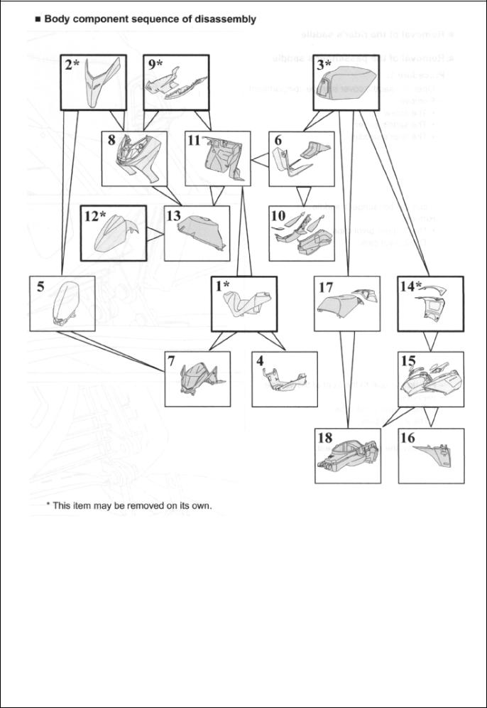
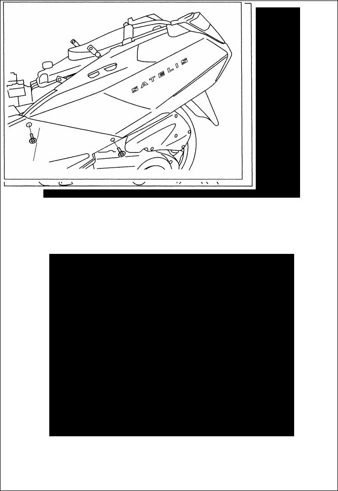
Removal of the rider’s saddle
Removal of the passenger’s saddle
Procedure 1.
-Open the saddle cover storage compartment.
-Remove:
. The screw.
. The saddle cover.
. The rider’s saddle.
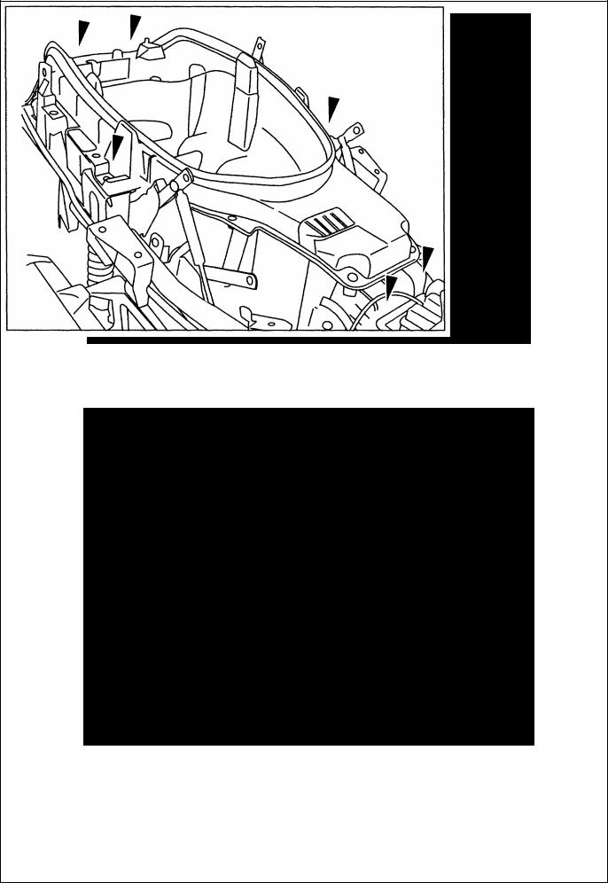
Open the passenger’s saddle.
- Remove:
. The 2 upper pivot clips.
. The 2 pivot pins.
4
-Flip up the seat to the front of the vehicle.
-Remove:
. The 2 lower pivot clips.
. The 2 pivot pins.
- Remove the passenger seat.
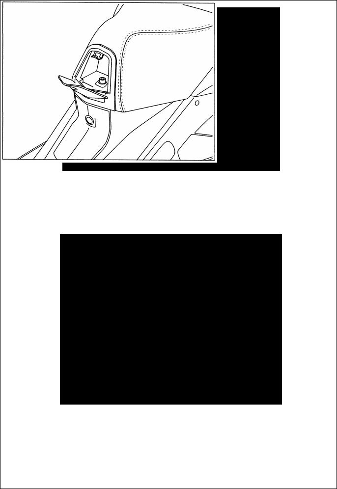
Removal of a RH or LH grab handle
Procedure 2.
-Remove the grab handle trim.
-Remove the 2 nuts and the screw that secure the handle.
-Remove the grab handle.
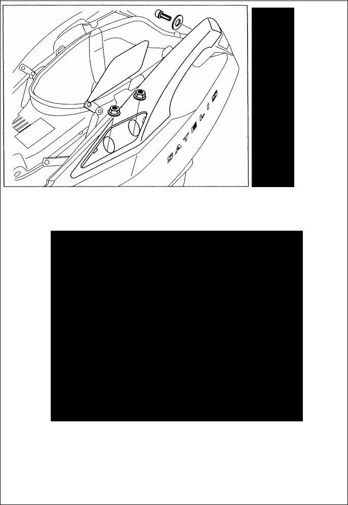
5
Removal of a RH or LH taillight taillight bulb
-Remove the grab handle. See: Procedure 2.
-Remove the taillight. (1 screw).
-Remove the 4 screws from the taillight unit.
-Separate the 2 parts in order to reach the bulbs.
6
Removal of a
Removal of a RH or LH side cover
Procedure 3
-Remove:
-The rider’s saddle. See: Procedure I. Page: 30.
-The grab handles. See: Procedure 2. Page: 31. S Remove the rear cover and its trim. (4 screw).
-Remove the 2 screws that secure the side cover linkage and the footboard.
7
-Push aside the footboard in order to clear side cover holder eyelet. Remove the side cover.
-Disconnect the taillight.
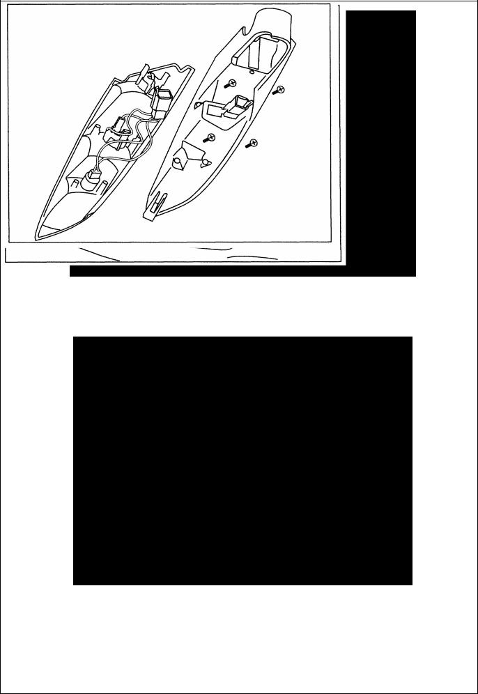
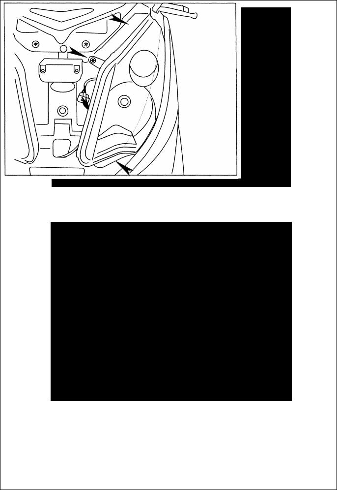
Removal of the storage compartment
Procedure 4.
-Remove the side fairings. See: Procedure 3. Page: 32.
-Disconnect the plate light and the saddle opening contact switch. Remove the storage compartment. (4 screws and 2 nuts).
8
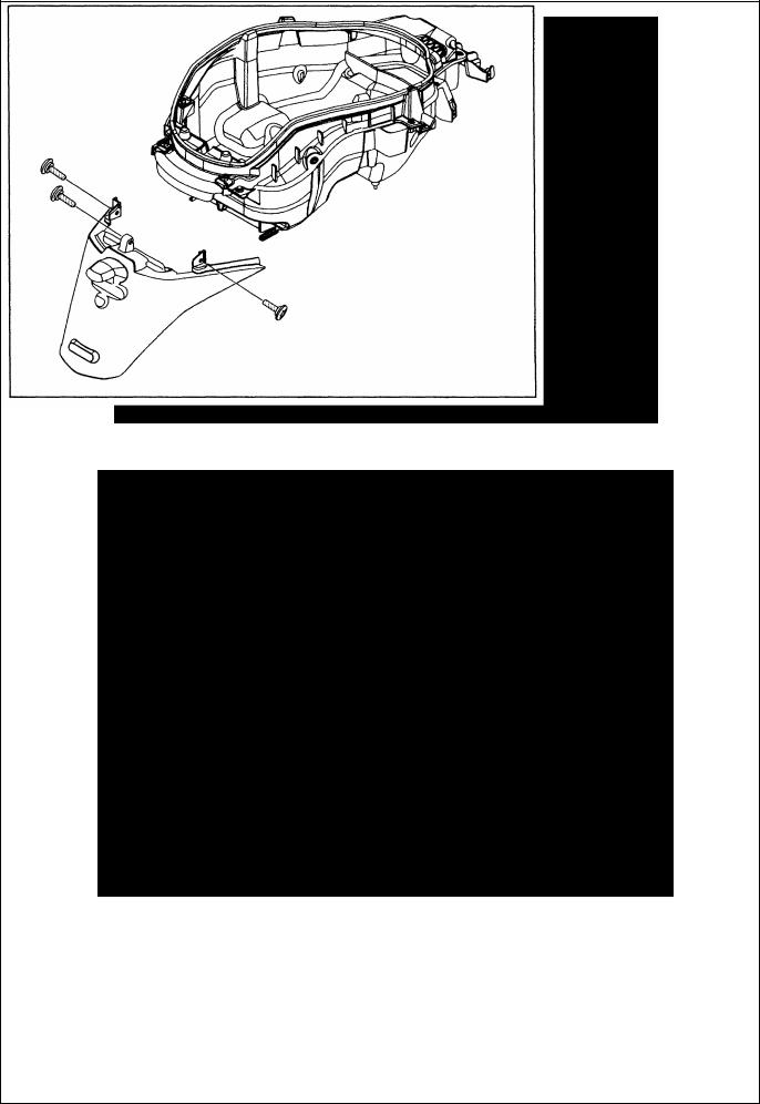
When dismantling the splash guard, fit the screws with standard thread lock.
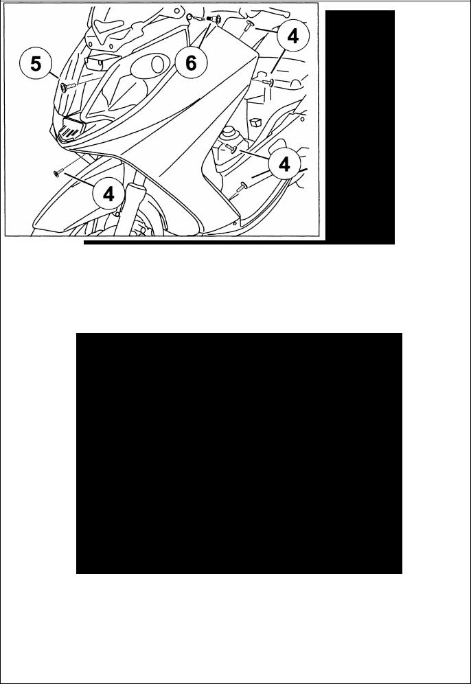
Removal of the tank covers
Procedure 5.
-The rider’s saddle. See: Procedure I.
-Page: 30.
Open the tank filler cap door.
Remove the 4 screws that secure the rear panel.
Remove the upper fairing.
9
-Remove the utility hanger. (2 screw).
-Remove 1 nut and 2 screws that secure the lower fairing.
-Remove the screw that secures the rear cover I footboard on each side of the vehicle. (1)
-Push slightly aside the cover I footboard assembly and remover the fuel tank cover panel by sliding it backwards.
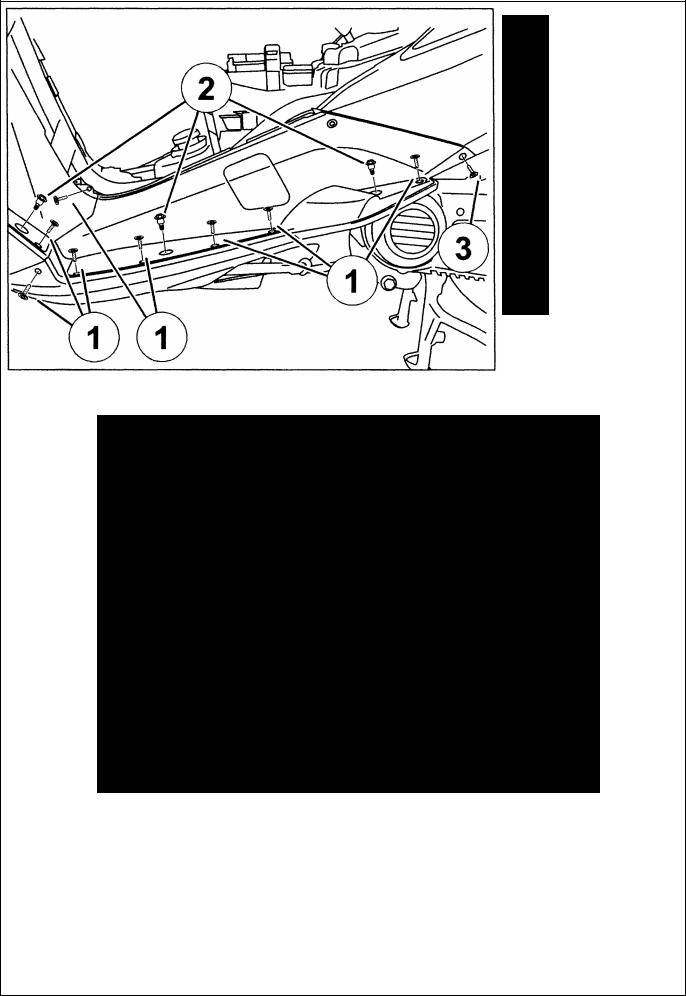
-Removal of a RH or LH footboard Procedure 6.
-Remove the tank cover panel. See:
Procedure 5.
-Remove the footboard mat.
-On each side remove:
. 8 plastic screws. (1)
. 3 washer head screws. 06 mm. (2)
. I washer head screw. 05 mm. (3)
10
-Press on the underbody panel in order to separate it from the footboard. (A)
-Separate the footboard from the rear fairing and bracket that anchors it to the body. (B)
-Separate the front of the footboard which is linked to the rear part of the leg shield panel.
(C)
11
-Removal of the front top cover panel
-Procedure 7.
-Remove the front top cover panel. (4 screw).
Removal of the headlight and sidelight assemblies Removal of the headlight bulbs
- Remove the front top cover panel. See: Procedure 7.
To reach the bulbs, remove the headlight. (3 screw)
12
-Removal of the front shield panel
-Procedure 8.
-Remove the front top cover panel. See:
-Procedure 7.
-On each side remove:
. 2 plastic screws that secure the front leg shield to the underbody cover. (1)
. 2 plastic screws that secure the footboard the underbody cover. (2)
- Push aside the underbody cover to reach the screw that secures the front shield panel. (3)
-On each side remove:
. 5 plastic screws. (4)
. I washer head screw. 06 mm. (5)
. I washer head screw. 05 mm. (6)
-Disconnect the headlights.
-Remove the front shield panel.
13
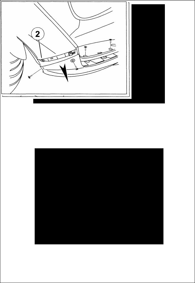
-Removal of the rear shield panel
-Remove the ignition key.
-Remove the tank cover panel. See:
-Procedure 5.
-Remove the front top cover panel. See:
-Procedure 7.
-Remove:
•The ignition switch trim.
•The handlebar upper fairing (8 screw) (1).
- On each side remove:
•2 plastic screws that secure the front leg shield to the underbody cover.
•2 plastic screws that secure the footboard to the underbody cover.
- Push aside the underbody cover to reach the screw that secures the front shield panel. (2)
14

- On each side remove:
•6 plastic screws. (3)
•2 washer head screws. 06 mm. (4)
-Separate the front shield panel from the rear shield panel in order to reach the bracket that connects the rear shield panel to the footboard. (A)
-Pull upwards the lower part of the shield panel in order to separate it from the footboard.
15
-Relove the eyelet (B) from the shield panel and the eyelet (C) from the instrument cluster fairing in order free the rear shield panel.
-Topple the rear shield panel while separating it from the footboards in order to reach the header tank and the accessory plug.
-Remove the header tank. (Right side).
-Disconnect the accessory plug. (Left side).
-Remove the rear shield panel.
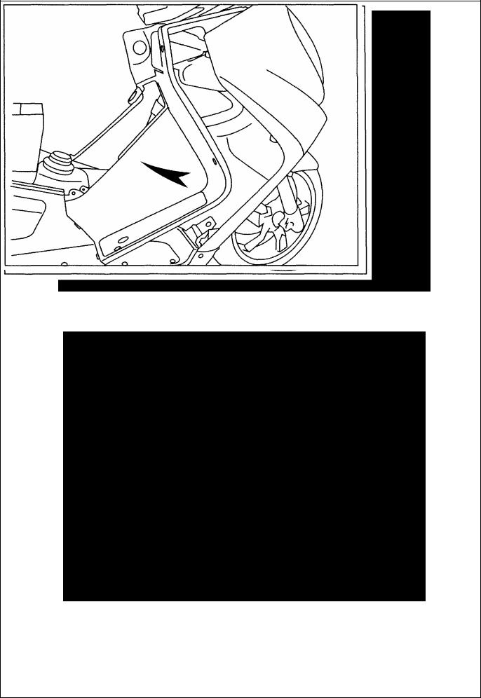
16

-Removal of the dirt shield
-Remove the front shield panel. See: Procedure 8.
-Remove the center screw which secures the dirt shield to the underbody cover.
-Disconnect the speed sensor.
-Pull the speed sensor control out of the dirt cover.
-Lift the front of the vehicle while making sure the wheel is in line with the vehicle.
-Remove the dirt cover by sliding it behind the wheel as shown.
-Removal of the battery holder Procedure 9.
-Remove the tank cover panel. See: Procedure 5.
-Disconnect and remove the battery.
-Unclip from the battery holder:
•The fuses. (1)
•The relays. (2)
•The diagnosis plug.(3)
- Remove the battery bracket. (2 screws and I nuts).
17
-Removal of the instrument cluster
-Remove:
-The front top cover panel. See: Procedure 7.
• The wind deflector.
• The handlebar upper fairing.
-On each side remove:
•1 plastic screw. (1)
•1 washer head screw. 05 mm. (2)
•1 washer head screw. 06 mm. (3)
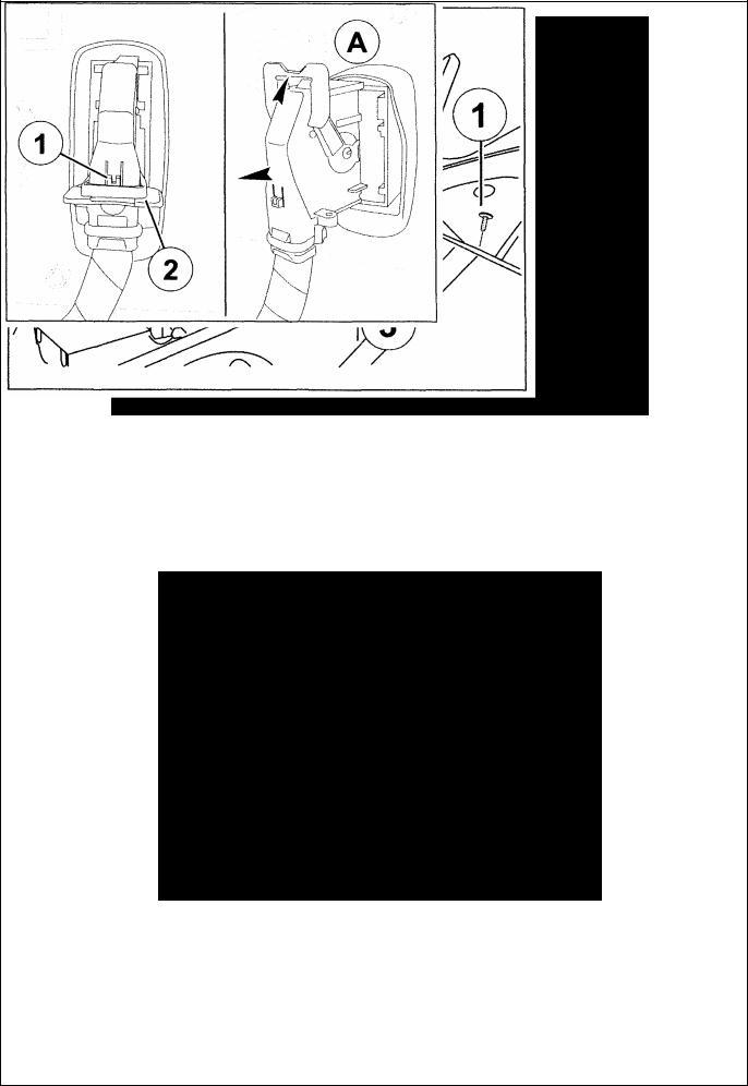
-Press the locking system (1) to actuate the
positioning lever (2) of the instrument cluster’s connector.
-Push the lever all the up (A) in order to remove the connector from the instrument cluster.
-Remove the instrument cluster fairing.
Note: When connecting, the lever must be pushed all the way to (A) in order not to damage the connector.
18

PIAGGIO MOTOR SERVICE STATION MANUAL
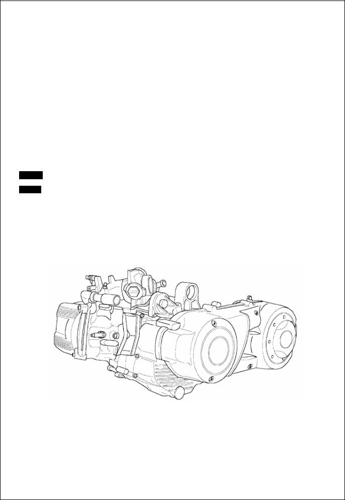
Engine Master 500 cc
19
SERVICE STATION MANUAL
PEUGEOT SATELIS 500 cc
This manual has been prepared by Piaggio & C. S.p.A. for use in the workshops of authorised Piaggio subagents.
It is assumed that the person utilising this manual for servicing or repairing Piaggio vehicles has a knowledge principles of mechanics and standard procedures for vehicle repair. Any important changes in vehicle
or specific repair operations will be divulged by means of updates to this manual.
Satisfactory repair or service cannot be achieved without the necessary equipment and tools. Refer of this manual concerning specific tools and equipment and the special tools catalogue.
Critical information in the manual is indicated as follows.
N.B.: Important information for facilitating and explaining a procedure.
Warning - Procedures that must be followed to avoid damage to the vehicle.
Caution - Procedures that must be followed to eliminate the risk of injury to repair / service personnel.
20
Specifications (500 cc 4-stroke, 4-valves H2 0 engine) |
|
|
|
|
|
ENGINE |
|
|
Type ............................................................................................................. |
single-cylinder, 4 stroke |
|
Bore......................................................................................................................................... |
92 mm |
|
Stroke....................................................................................................................................... |
69 mm |
|
Displacement........................................................................................................................ |
460 cm3 |
|
Compressionratio.................................................................................................................... |
10.5 : 1 |
|
Timing .............................................................................................. |
chain-operated overhead |
|
single-shaft flywheel side, integrated phonic wheel, 4- valves and automatic starting valve lifter
Valves play |
...............................................................................................................: intake |
|
0.20 mm |
|||
|
|
............................................................................................................exhaust |
|
0.20 mm |
||
Valves play |
|
|
|
|
|
|
adjustment........................................................................................ |
|
threaded register on equalizers |
||||
Idle speed...................................................................................................................... |
|
1450±50 rpm |
||||
CO% value ................................................................................................................................. |
|
1±1. |
||||
Starting system ............................................................................................................ |
|
electric starter |
||||
Lubrication........................................... |
|
trochoid pump (inside the crankcase), oil filter and pressure |
||||
adjustment by-pass |
|
|
||||
Lubrication pressure.................................................................................................................. |
|
4 bar |
||||
Minimum allowed pressure (at 100°C) |
................................................................................... 0.8 bar |
|||||
Fuel system ........................................................ |
|
electronic injection with electric fuel pump, throttle |
||||
body Ø 38mm and single injector |
|
|||||
Max power |
|
|
||||
(at crankshaft) ...................................................................................... |
|
29 kW (39 CV) bei 7250 rpm |
||||
Max torque |
|
|
|
|
|
|
(at crankshaft) .................................................................................... |
|
40 N·m (4 Kgm) bei 5500 rpm |
||||
Cooling system |
.................... |
liquid, by means of motorized pump, 3-way thermostat and electric |
||||
fan. |
|
|
||||
Transmission |
............................. |
automatic speed variator by means of expanding pulleys, V-belt, |
||||
automatic clutch, reduction gear, and transmission compartment cooling by air forced-circulation.
Ignition type |
.................... |
|
high efficiency inductive type integrated with injection, variable spark |
|
advance and separated high voltage coil |
||||
|
|
|
||
Spark advance |
|
|
||
(before T.D.C.) ............... |
variable controlled by injection |
|||
power unit |
|
|||
Spark plug |
............................................................................. |
CHAMPION RG 6 YC NGK CR7 EKB |
||
Engine-wheel ratio ............................................................................. |
short: 1/11.988 long: 1/ 4.86 |
|||
Engine oil ................................................................................................ |
SAE 5W/40 exceeding API |
|||
SJ specifications
Quantity ……………………….................................................................................................. ~ 1.7 l
Hub oil........................................................................................................................ |
TUTELA ZC 90 |
Quantity .................................................................................................................................... |
250cc |
Cooling system capacity ........................................................................................................... |
~ 1.8 |
21
Spark plug
Check and replacement
Warning
-Remove the spark plug when the engine cold. Replace the spark plug every 12,000 Km. The use of unsuitable control units or spark plugs other than those specified can seriously damage the engine.
Recommended spark plug: CHAMPION RG 6 YC NGK CR 7 EKB
-Put the vehicle on its central stand.
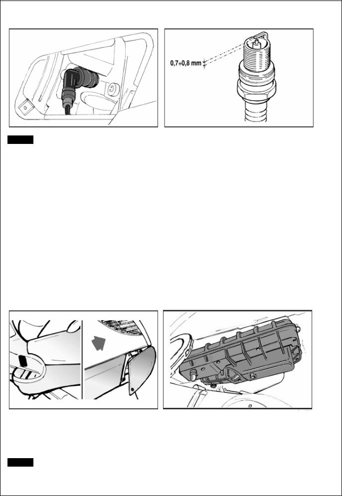
-Open the door on the left side of the vehicle by levering in the recess in the lower part of the door after removing the screw.
-Disconnect the spark plug high voltage cable cap;
-Unscrew the spark plug with the spanner provided; check the spark plug to see if the insulator is cracked, the electrodes are worn out or excessively sooty.
Also check the condition of the sealing washer and measure
: 0.7 - 0.8 mm
-If necessary adjust the gap by carefully bending the side electrode. If the spark plug has any of the defects mentioned above replace it with a plug of the recommended type;
-Insert the plug into the hole with the proper inclination, screw it in fully by hand and then tighten it with the specially designed spanner.
Tightening torque: 10 N·m (1 Kg·m)
-Push the spark plug cap all the way down onto the spark plug and then proceed to the reassembly.
Air filter
-Remove the left-hand lower side panel
-Remove the cleaner cap after unscrewing the eight fixing screws, including one screw of the knob type.
-Pull out the filter element.
-Replace the air filter with a new one.
N.B.: Check and if necessary blow the air filter every 6,000 km. Direct the air jet from the inside to the outside of the filter (i.e. in the opposite direction to the air flow during normal engine operation). Warning
- If the vehicle is mostly used on dusty roads, the air filter needs to be cleaned and replaced at shorter intervals than indicated in the Maintenance Schedule.
22
Warning
- Do not run the engine if the air filter is not in place as this would result in excessive wear of the cylinder and piston as well as in damage to the throttle body.
Engine oil level
In four-stroke engines oil is used to lubricate the valve gear components, the crankshaft bearings and the thermal unit. A lack of engine oil can cause serious damage to the engine.
In all four-stroke engines, oil deterioration and consumption are, to some extent, normal, especially during running-in. Consumption partly depends on the riding style (for example, constantly riding at full throttle increases oil consumption).
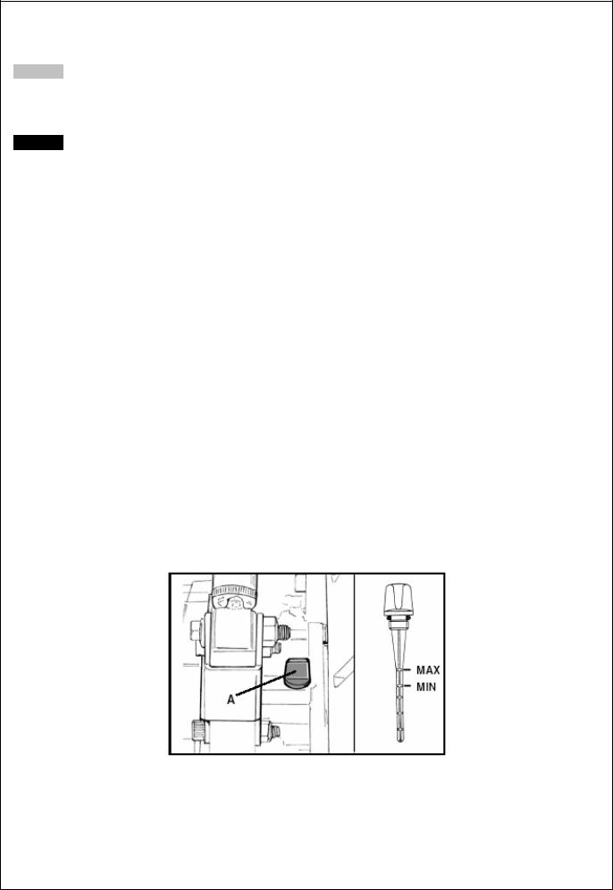
Checking the oil level
Perform this operation when the engine cold, as described below:
1)Put the vehicle on its central stand on a flat surface.
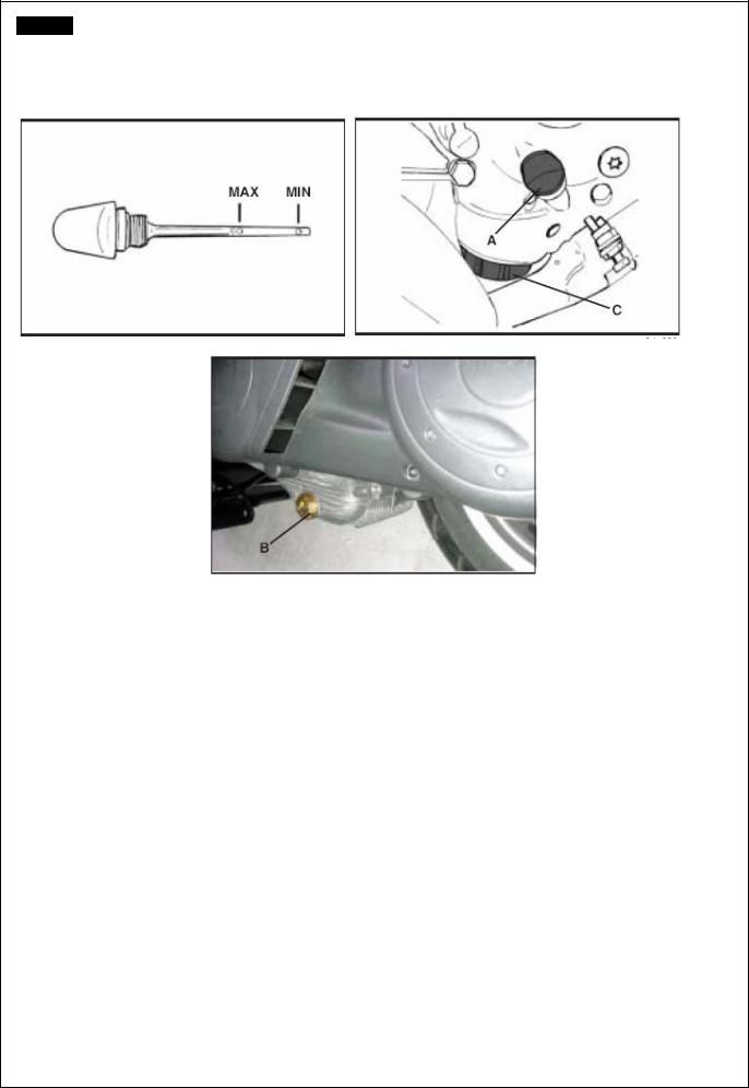
2)Unscrew dipstick «A», dry it with a clean cloth and refit by screwing it completely.
3)Remove the dipstick again and check that the oil level is between the MAX and MIN marks on the dipstick; top up if necessary.
Il riferimento del livello di MAX indica una quantità di circa 1700 cc di olio nel motore. The level will be lower if checked after using the vehicle
(i.e. when the engine is hot). To obtain a correct indication
of the oil level, wait for at least 10 minutes after switching off the engine. When the oil level is at MAX the engine contains 1700 cc of oil.
23
Replacing the filter
Warning
- Do not dispose of the oil in the environment. Carry out the disposal of the oil, the gasket and the filter in accordance with the law.
Warning - To avoid burns, take care not to touch hot engine parts.
-Remove the silencer.
-Remove filler plug «A».
-Remove and clean the drain plug gauze strainer with compressed air.
-Using a strap wrench for filters, remove cartridge filter «C».
-Ensure that the O-rings on the prefilter and the drain
plug are in good condition.
-Lubricate the O-rings and then refit the gauze strainer and the oil drain plug. Tighten the drain plug with the prescribed torque.
-Fit a new cartridge filter after lubricating the O-ring. Turn in until the gasket makes contact and then screw it with the prescribed torque.
-Reinstall the silencer.
-Add engine oil as previously described.
Tightening torque: Oil filter: 12 - 16 N·m
Recommended oil: Selenia HI Scooter 4 Tech
------------------------------------------------------------------------------------------------------------------------------------------------------------
Checking the hub oil level
Put the vehicle on the central stand on level ground.
-Unscrew oil dipstick «A», wipe it with a clean cloth,reinsert it and then screw it in fully.
-Pull out the dipstick again and check that the oil level is between the MIN and MAX marks (see figure); if the level is below the MIN mark, top up with oil.
-Reinsert the dipstick and screw it tight. MAX
----------------------------------------------------------------------------------------------------------------------------------------------
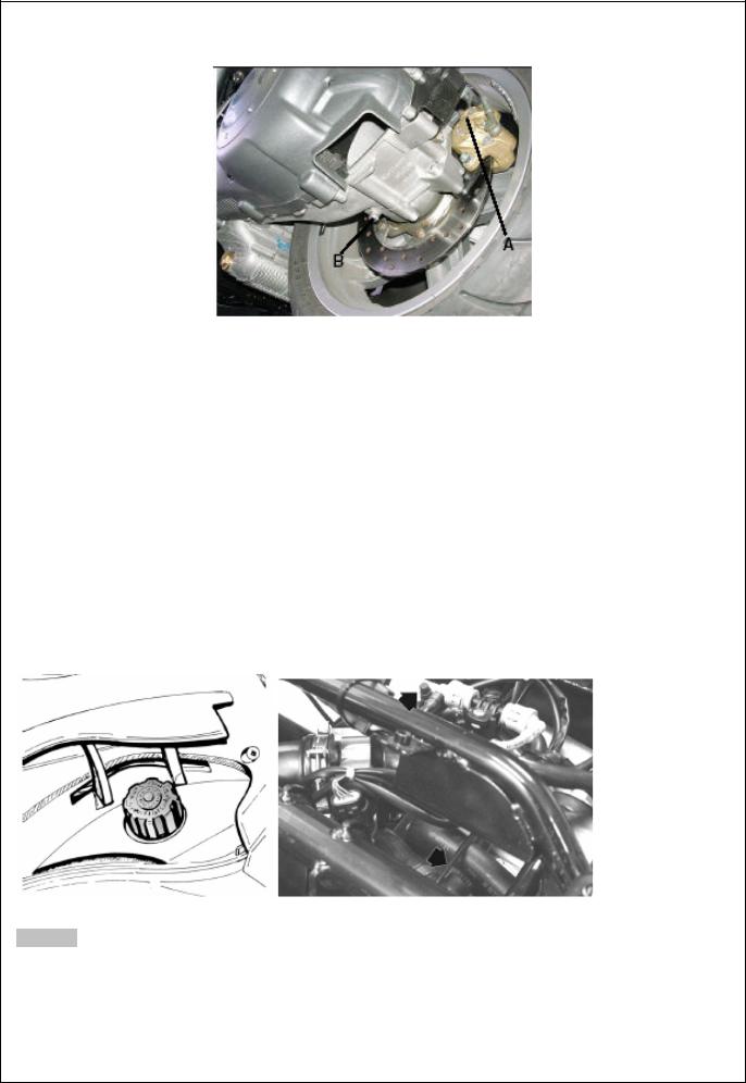
Renewing the hub oil
-Remove oil filler plug «A».
-Unscrew oil drain plug «B» and drain all the oil.
-Retighten the oil drain plug and then fill the hub with fresh oil.
24
Hub oil capacity: ~ 250 cc
Recommended oil: TUTELA ZC 90
------------------------------------------------------------------------------------------------------------------------------------------------------------
Engine cooling Adding coolant and bleeding air from the system.
The level of the fluid must be checked every 6,000 km when the engine is cold.
Follow these steps:
-Put the vehicle on the central stand on level ground.
-Remove the expansion tank cap and top up if the coolant is below or near the MIN level in the expansion tank. The level of the fluid should always be between the MIN and MAX marks.
-To have an indication of the coolant level, refer to the groove in the plastic strip that can be seen through the coolant filler hole. The upper and lower parts of the groove correspond to the MAX and MIN levels respectively.
-The coolant consists of a 50 percent mixture of demineralized water and antifreeze solution with a base of ethylene glycol and corrosion inhibitors. Total coolant capacity: ~ 1.8 lt
-To check the presence of air in the circuit follow the procedure described in Chapter 11 - Cooling.
-Switch off the engine and allow it to cool down. After a few minutes, remove the expansion tank cap and check the level of the fluid.
-If necessary, top up by pouring fresh coolant into the expansion tank up to the correct level.
Warning
- To prevent the coolant from leaking out of the expansion tank during use, be sure to never exceed the MAX level when refilling.
25
 Loading...