


 Loading...
VersaCam IC-360 Manual Version 1.4
VersaCam® IC-360 User’s Guide
*This manual is for VersaCam IC-360 Firmware version 1.2.1. If you have later version of firmware, please download the last updated user’s guide from Pentax’s website (http://www.pentaxtech.com).
System Requirements
Network Access For a VersaCam IC-360
•Network: 10 Base-T LAN
(Leased line, xDSL, Cable Modem, ISDN)
PC Access to a VersaCam IC-360 (this will
result in frame rates of 2-to-15 fps – other system configurations will result in other frame rates)
•Processor: Pentium II and above
•RAM: Minimum 64MB
•OS: Windows 95/98/NT/2000/XP/Mac, Linux
•Screen Resolution: 1024 X 768 pixels and above (standard VGA)
Pentax Technologies Corp.
i
©2002 Pentax Technologies Corporation. All Rights Reserved. Printed in USA. Specifications subject to change without notice.
P/N 205255-551
Pentax is a registered trademark of Asahi Optical Co., Ltd.
VersaCam is a registered trademark of the Asahi Optical Co., Ltd.
Windows is a registered trademark of the Microsoft Corporation.
Netscape is a registered trademark of the Netscape Corporation.
Internet Explorer is a trademark of the Microsoft Corporation.
Pentium is a registered trademark of the Intel Corporation
All other trademarks are the property of their respective owners.
ii |
VersaCam IC-360 User’s Guide |

FCC Compliance Statement
Caution: Any changes or modifications not expressly approved by the Pentax could void the user’s authority to operate this equipment.
Note: This equipment has been tested and found to comply with the limits for a Class A digital device, pursuant to part 15 of the FCC Rules. These limits are designed to provide reasonable protection against harmful interference when the equipment is operated in a commercial environmental. This equipment generates, uses, and can radiate radio frequency energy and, if not installed and used in accordance with the instruction manual, may cause harmful interference to radio communications. Operation of this equipment in a residential area is likely to cause harmful interference in which case the user will be required to correct the interference at their own expense.
Warning
This is a class A product. In a domestic environment, this product may cause radio interference in which case the user may be required to take adequate measures
iii |
VersaCam IC-360 User’s Guide |

Important Notice
1.The VersaCam IC-360 is for indoor use. Note that the CCD (charged coupled device) inside the product can be damaged permanently if the camera lens is exposed to direct sunlight. If your application demands prolonged exposure to sunlight, you should consider equipping it with a sun visor.
2.The VersaCam IC-360 is not weatherproof. You should consider the environmental specifications that are included in this manual. In case of outdoor use, you should equip the camera with a weatherproof case to protect from water, moisture, or extreme temperatures (higher or lower than specification). For VersaCam IC-360 cleaning, gently wipe with a clean dry cloth.
3.Be sure to use the DC adapter that is provided. Connecting a VersaCam IC-360 directly to AC current will cause damage to the camera.
4.Be cautious in handling the VersaCam IC-360. Physical shocks may harm the product.
5.The VersaCam IC-360 is made of aluminum case. When installing the camera, be sure it is attached tight and stable to avoid any injures. Be careful to locate the camera where children cannot reach it.
6.If the VersaCam IC-360 does not operate properly, please contact the closest local Pentax distributor for service. Do not disassemble the product or the service warranty may be voided.
7.Camera surveillance laws may differ for each country. Therefore, please contact local authorities first to avoid any surveillance law violations and to apply for authorized purposes only, if necessary.
iv |
VersaCam IC-360 User’s Guide |

|
CONTENTS |
|
|
I. Introduction .......................................................................................................................... |
|
1 |
|
II. Product Descriptions............................................................................................................ |
|
3 |
|
A. Camera Kit Contents.............................................................................................................. |
|
3 |
|
B. VersaCam IC-360 Overview and Description....................................................................... |
|
3 |
|
C. Descriptions of Rear Ports (RS-232 and Digital Input)........................................................ |
|
4 |
|
D. Description of LEDs............................................................................................................... |
|
5 |
|
III. VersaCam IC Series Installation Summary, Connection, & Placement ............................... |
6 |
||
Summary..................................................................................................................................... |
|
6 |
|
IV. Assigning IP Address and Configuring the Administrator’s Data ............................... |
7 |
||
A. Connecting a VersaCam IC Series to a PC ........................................................................... |
|
8 |
|
1) |
Connecting a VersaCam IC-360 to the Internet or a LAN................................................ |
|
8 |
2) |
Connecting a VersaCam IC Series to a PC........................................................................ |
|
8 |
B. Assigning an IP address and configuring administrator’s data with the setup program ... |
10 |
||
1) |
Starting the VersaCam IC Series Setup Program............................................................ |
|
10 |
2) |
Assigning a VersaCam’s IP Address................................................................................ |
|
10 |
3) |
Configuring Administrator’s Data..................................................................................... |
|
10 |
C. Assigning an IP Address with the ARP Command .............................................................. |
|
11 |
|
1) |
Using ARP in Windows 98 and NT................................................................................... |
|
11 |
2) |
Using ARP in Windows 95................................................................................................ |
|
11 |
3) |
Verifying Installation........................................................................................................ |
|
11 |
V. Accessing a VersaCam IC Series Homepage & Monitoring |
Real-Time Images.......... |
13 |
|
A. Starting a Web Browser ...................................................................................................... |
|
13 |
|
B. Login page............................................................................................................................ |
|
13 |
|
1) |
ID and password............................................................................................................... |
|
13 |
2) |
Behind A Firewall............................................................................................................. |
|
13 |
3) |
VersaCam IC Series Plug-in for Netscape Users ........................................................... |
|
14 |
4) |
VersaCam IC Series Active-X for MS Explorer Users................................................... |
|
14 |
5) |
FAQ................................................................................................................................... |
|
14 |
C. Viewing With The VersaCam IC-360.................................................................................. |
|
15 |
|
1) |
Real-time monitoring through the default viewer........................................................... |
|
15 |
2) |
720x486 Viewer ............................................................................................................... |
|
17 |
3) |
Server Push Viewer ......................................................................................................... |
|
18 |
VI. Configuring Administrator’s Data at Homepage .................................................................. |
|
20 |
|
A. Administrator Login............................................................................................................. |
|
20 |
|
1) |
Accessing through the Setup Program ............................................................................ |
|
20 |
2) |
Accessing through Web Browser..................................................................................... |
|
20 |
B. Configuring Administrator’s Data at the Homepage........................................................... |
|
21 |
|
1) |
System Configuration ....................................................................................................... |
|
21 |
2) |
User Configuration ........................................................................................................... |
|
22 |
3) |
Network Configuration ..................................................................................................... |
|
23 |
4) |
Security Configuration...................................................................................................... |
|
25 |
5) |
Video Configuration.......................................................................................................... |
|
26 |
6) |
Application Configuration................................................................................................. |
|
28 |
7) |
Pan/Tilt/Zoom Configuration............................................................................................ |
|
31 |
8) |
Serial Port Configuration.................................................................................................. |
|
34 |
9) |
Digital I/O Configuration................................................................................................... |
|
35 |
10) Alarm Configuration ....................................................................................................... |
|
36 |
|
11) Custom Configuration..................................................................................................... |
|
37 |
|
12) Goto Viewer Page........................................................................................................... |
|
38 |
|
Appendix 1 - Detailed Specifications of VersaCam IC-360 ...................................................... |
|
39 |
|
|
v |
VersaCam IC-360 User’s Guide |
|
Appendix 2 - Frequently Asked Questions .............................................................................. |
41 |
||
1. Frequently Asked Questions................................................................................................ |
|
41 |
|
1.1. VersaCam IC Series Features..................................................................................... |
41 |
||
1.2. VersaCam IC Series Installation ................................................................................. |
43 |
||
1.3. Control and Utility Programs....................................................................................... |
48 |
||
1.4. Inserting Images into HTML Pages............................................................................ |
50 |
||
Appendix 3 - Utilizing IP Addresses on a Local Network ........................................................ |
53 |
||
Appendix 4 |
- Updating VersaCam IC-360 Firmware ............................................................... |
55 |
|
Appendix 5 |
- VersaCam IC-360 |
Physical Installation Guide ................................................... |
57 |
Appendix 6 |
- VersaCam IC-360 |
Power Supply Installation Guide .......................................... |
59 |
Appendix 7 |
- VersaCam IC-360 |
External Device Connection Information .............................. |
61 |
vi |
VersaCam IC-360 User’s Guide |
I.Introduction
•What is a VersaCam IC-360?
The VersaCam IC cameras are Internet-based digital network cameras, which provide high-resolution imaging and use image compression via a network. They connect directly to an Ethernet network and provide live motion color pictures over the Internet or individual frames by E-mail or FTP.
The VersaCam IC is a microprocessor-based device that contains a digital color camera, web server functionality, optimized hardware for image compression, and a physical Ethernet connection. Therefore it does not require any extra software or hardware. Simply provide power and connect a LAN cable to the VersaCam IC.
The VersaCam IC Series generates pictures in Wavelet format, which compresses images more effectively than standard JPEG does. Moreover, Wavelet progressively generates pictures from low rates of resolution, so it reduces waiting time for users.
VersaCams fit in a wide range of applications to monitor places and objects. Common applications are: construction areas, important equipment, banks, hospitals, amusement parks, highways, and child care centers. Using a VersaCam IC-360, you can conveniently monitor any place thorough web browsers from remote sites.
• Features and Benefits
Ease of Use – VersaCam IC Series does not require the use of a PC frame grabber card nor interaction with any other server. The only software required is Netscape Navigator 4.x or Microsoft Internet Explorer 4.x or above. Since it has a complete plug-and-picture functionality, the only step one has to take is to assign a valid IP address.
Open Standards Environment - Supporting TCP/IP networking, SMTP E-mail, FTP, HTTP and other Internet-related protocols, the VersaCam IC Series can be used in mixed operating system environments, such as Windows, UNIX, Macintosh and OS/2. It integrates easily into other WWW/Intranet applications and CGI scripts.
Simple Administration - Using a standard Web browser, you can configure and manage a VersaCam IC-360 directly from its own Web pages. When a new firmware release becomes available, you can simply upgrade all of your VersaCam IC Series camera products remotely over the network.
Wavelet Image Format - As opposed to many inferior solutions that need to split image files prior to broadcast, VersaCam delivers complete high-quality and highly compressed pictures in Wavelet format. Wavelet has 30%~300% higher image compression rates than standard JPEG. Wavelet technology allows the integrity of your pictures to be higher than other web cameras and to be viewed with crystal clarity and high speed.
External Device Connection - Using an auxiliary Input/Output connector, you can connect your VersaCam IC Series to a variety of external devices, such as IR-sensors, switches, alarm relays, or CCTV analog video monitors (output). In combination with the programmable alarm facilities, you can quickly develop various security applications that are triggered on time-based or alarm-based events.
1 |
VersaCam IC-360 User’s Guide |
User’s Programmable Space – VersaCam IC Series cameras contain user-programmable and user-configurable spaces that are about 6MB out of 8MB total Flash Memory. This means you can create your own web server, with your own homepage using your VersaCam.
Embedded Linux Operating System – VersaCam IC Series adopts cutting-edge technologies of digital image processing & networking. Since VersaCam IC Series consists of a high performance CPU (32-bit RISC), running embedded Linux, it allows up to 100 users to be connected to a VersaCam IC Series simultaneously.
2 |
VersaCam IC-360 User’s Guide |
II. Product Descriptions
A. Camera Kit Contents
* Unpack and check all the items below.
Item |
Description |
|
Remarks |
|
|
|
|
VersaCam IC-360 |
Web Camera Server |
|
|
|
|
|
|
AC Adapter & Power cable |
100-250VAC, 0.5A, 50/60 Hz |
|
|
12VDC, 3.5A Output |
|
|
|
|
|
|
|
Lens |
Optical 16x: 3.9mm ~ 62.4mm |
|
Included |
Digital 8x, Auto-iris & Auto-Focus |
|
||
|
|
|
|
Manual |
VersaCam IC-360 User's Guide |
|
On CD |
|
|
|
|
Ethernet standard |
3-foot (1 m) cable, RJ45 connectors |
|
White colored |
(straight-through) Cable |
|
connectors |
|
|
|
||
Ethernet Crossover Cable |
3-foot (1 m) cable, RJ45 connectors |
|
Red colored |
|
connectors |
||
|
|
|
|
Bracket & Safety Wire |
Ceiling Attachment Device |
|
|
|
|
|
|
Setup Disk (CD) |
Setup Software, User’s Manual, |
and |
|
Web Site Programmer’s Guide |
|
|
|
|
|
|
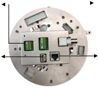
B. VersaCam IC-360 Overview and Description
RS-232 for Audio |
|
|
|
Digital Input |
|
|
|
||
|
||||
Device (Optional) |
|
|
|
|
|
|
|
|
|
 Video Output (BNC)
Ethernet (RJ-45)
Power Supply
3 |
VersaCam IC-360 User’s Guide |

Connector Name |
Description |
Remarks |
|
|
|
BNC connector |
Output internal video signal through a coaxial cable. |
|
|
|
|
Power connector |
To supply power from the provided power supply unit |
|
(12VDC, 1.5A) |
|
|
|
|
|
|
|
|
RS-232 Connector |
To connect external devices such as a device for audio |
|
transmission. |
|
|
|
|
|
Digital Input Terminal |
To connect external sensors. |
|
|
|
|
RJ-45 Ethernet port |
To connect 10 Base-T Ethernet cable. |
|
|
|
|
C. Descriptions of Ports (RS-232 and Digital Input)
Digital Input: To connect external devices such as infrared sensors. There are 2 pairs of isolated input ports. See Appendix 7 for details.
S1+ S1S2+ S2-
|
|
|
|
|
|
|
|
|
|
|
|
|
|
|
|
|
|
|
|
|
|
|
|
|
|
|
|
|
|
|
|
|
|
|
|
Pin Name |
|
|
|
|
|
|
Description |
||||
|
|
||||||||||
|
To connect external devices such as infrared sensors. |
||||||||||
|
Solid State Relay (Optically isolated) |
||||||||||
S1+, S1- |
- Current |
||||||||||
&. Typical: 16mA
S2+, S2- . Maximum: 20mA (Maximum Rating: 60mA) - Pulse time
. Minimum: 200msec
- Internal resistor: 330 ohm
RS-232: To connect VersaCam IC Series to an Audio Device.
RX TX GND
|
|
|
|
|
|
|
|
|
|
|
|
|
|
|
|
|
|
|
|
|
|
|
|
|
|
|
|
|
|
|
|
|
|
|
|
|
4 |
|
|
|
VersaCam IC-360 User’s Guide |
|||
D. Description of LEDs
Data LED: This LED indicates the status of data transmission. After power is supplied, it is on for the first 4-5 seconds and then it goes off. It blinks continuously when a user accesses the VersaCam and is transmitting data.
Network Status LED: This LED indicates the status of the network. After power is supplied, it is on for the first 1-2 seconds, and then it blinks every two seconds as long as the network is connected.
|
Malfunction Indications |
1. |
Network Malfunction |
• Network Status LED blinks once every 4 seconds |
|
• |
Check if the Ethernet cable is connected properly, if the right Ethernet cable is being |
|
used, or if the Network is working. |
2. |
Software Malfunction |
•Both LEDs are on and they blink 6 times rapidly every 10 seconds. Contact Customer Support for assistance.
•After being on for one second, both LEDs blink 6 times rapidly. Then the network status LED stays on and the Data LED stays off.
Re-installing the firmware can solve this problem. Contact Customer Support for assistance.
5 |
VersaCam IC-360 User’s Guide |

III. VersaCam IC Series Installation Summary, Connection, & Placement
Summary
•Connect an Ethernet cable between the VersaCam IC-360 Ethernet Port and your local network.
•Connect the Power Supply to your VersaCam IC-360. Confirm that the Network Status LED blinks
•Install the setup program for the VersaCam IC-360 on a PC on your local network.
•Assign an IP address to the VersaCam IC-360 and configure the administrator’s data.
•Configure the users’ data.
•Disconnect the IC-360 from the local network and place it for your application* then re-connect power and an Ethernet connection.
•Set the preset aiming positions as desired.
*You must use a specialized bracket for ceiling attachment of VersaCam IC-360.
Caution
•Please note that exposing the camera lens to direct sunlight may cause permanent CCD (charged coupled device) damage.
•If your application demands prolonged or direct exposure to sunlight, you should consider a sunshade.
6 |
VersaCam IC-360 User’s Guide |

IV. Assigning IP Address and Configuring the Administrator’s Data
* Important *
To access a VersaCam, you first have to assign an appropriate IP address. When you assign an IP address to a VersaCam, make sure to use an unassigned IP address – do not use the default or example IP address.
Terminology
IP Address
An IP address is an identification code for computers and devices on a TCP/IP network. Networks using TCP/IP protocol route messages based upon the IP address of the destination. Within a closed network, IP addresses can be assigned at random as long as each one is unique. However, connecting a private network to the Internet requires using registered IP addresses to avoid duplicates. An IP address can be acquired from a network administrator or an Internet service provider.
MAC Address (Media Access Control Address)
A MAC address is a hardware identification code that uniquely identifies each node of a network. The MAC address of VersaCam is a 12-digit number. A unique MAC address can be found on the label at the bottom of each VersaCam.
Crossover Cable
The crossover cable (red) provided with the VersaCam is used to connect the VersaCam directly to a PC. A hub is not necessary to connect the VersaCam to a PC if a crossover cable is used.
Direct Cable
The direct cable (white) should be used if a hub is used as an intermediary between the VersaCam and a PC.
10-Base T
This describes the speed and cabling used to make 10-Megabit/second Ethernet connections. The camera cannot be directly connected to a network that allows only 100-Base T connections.
7 |
VersaCam IC-360 User’s Guide |
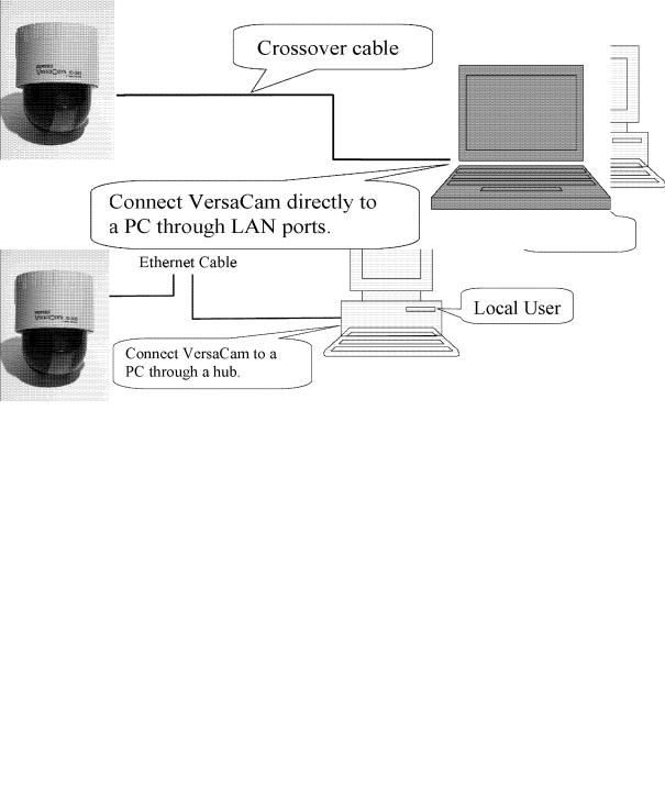
A. Connecting a VersaCam IC Series to a PC
1)Connecting a VersaCam IC-360 to the Internet or a LAN.
•You may use a standard Ethernet cable (white colored connectors) to connect a VersaCam IC-360 to the Internet or a LAN. With this connection, a remote user may not access a VersaCam IC-360 before the local user configures their network settings.
2)Connecting a VersaCam IC Series to a PC.
•You may use a crossover cable (red colored connectors) to directly connect a VersaCam to a PC. This connection is only used to configure the VersaCam.
8 |
VersaCam IC-360 User’s Guide |

IP Address Assigning Methods
•With the setup program
-Assemble and place the VersaCam.
-Assign an IP address to the VersaCam using the setup program on a local network.
-If it is impossible to assign an IP address with the setup program, try assigning it with the DOS ARP command.
•With an ARP command
-Assemble and place the VersaCam.
-Assign an IP address using the DOS ARP command on a local network.
9 |
VersaCam IC-360 User’s Guide |
B. Assigning an IP address and configuring administrator’s data with the setup program
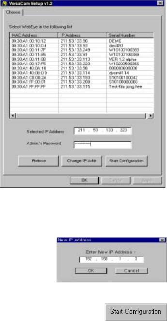
1) Starting the VersaCam IC Series Setup Program
Click the file ‘Setup.exe’ on your PC. When the setup program is executed, the setup program detects and shows every VersaCam IC Series connected to the local network.
Among the VersaCams, choose the one to which you want to assign a new IP address. (The default address in the figure is 211.53.133.223). To choose a VersaCam, click on its MAC address or IP address.
When a VersaCam is selected, an IP address shows in the ‘Selected IP Address’ window. You must key in a password in the blank ‘Admin’s Password’ window to assign (or change) the IP address to the VersaCam. The default password is ‘admin’.
You can now change the IP address by clicking ‘Change IP Addr’ button or set up by clicking ‘Start Configuration’ button.
If the VersaCam has any problems, you can reboot without turning off the power supply. The ‘Reboot’ button works as a reset switch.
2) Assigning a VersaCam’s IP Address
After keying in the administrator’s password, click the ‘Change IP Addr’ button to change your VersaCam’s IP address. Type in a new IP address that you are going to assign to your VersaCam. Then confirm it with the ‘OK’ button.
3) Configuring Administrator’s Data
After assigning a new IP address to a user’s VersaCam, you may configure the administrator’s data for that camera. When you click ‘Start Configuration’ button, the Setup program automatically connects you to the Admin page of
VersaCam Homepage. (For more detailed information, refer to Chapter VI ‘Configuring Administrator’s Data at the Homepage’)
10 |
VersaCam IC-360 User’s Guide |

C. Assigning an IP Address with the ARP Command
1) Using ARP in Windows
When the PC’s operating system is Windows 98, 2000, Me, XP, or NT, follow the steps below.
• Open a DOS window and type the following commands.
Arp |
-s <VersaCam IP address> <VersaCam MAC address> |
Ping |
<VersaCam IP address> |
|
|
• Example
Arp -s 192.168.1.3 00-40-8c-10-00-86
Ping 192.168.1.3
2) Using ARP in Windows 95
When the PC’s operating system is Windows 95, follow these steps.
• Open a DOS window and type the following commands.
Arp |
-s <VersaCam IP add.> <VersaCam MAC add.> <my PC IP add.> |
Ping |
<VersaCam IP address> |
|
|
• Example
Arp |
-s 192.168.1.3 00-40-8c-10-00-86 192.168.1.2 |
Ping |
192.168.1.3 |
|
|
3) Verifying Installation
After completing the tasks above successfully, the following messages or similar ones will appear on the screen:
Request timed out
:
Request timed out
Reply from 200.243.232.178: bytes=32 time=2ms TTL=255 Reply from 200.243.232.178: bytes=32 time=2ms TTL=255
Ping statistics for 200.243.232.178:
Packets: Sent = 4, Received = 4, Lost = 0 (0% loss),
Approximate round trip times in milliseconds:
Minimum = 1ms, Maximum = 2ms, Average = 1ms
If you don’t receive the reply by using the 'ping' command, try pressing 'F3' and 'Enter' keys again. Normally ‘Request timed out’ messages appear 7 times before you receive a proper reply.
11 |
VersaCam IC-360 User’s Guide |
Data loss number may be from 0% to 99%. This is a normal reply. If the statistic shows ‘100% loss’, you should check to see if the network lines and connection status are stable, if the IP address which is assigned to VersaCam is available, and whether the PC you are using has the same local network’s IP address as the VersaCam. The same local IP address on a “C” grade network means that the first 3 sets of numbers are same but the fourth is different. For example, 192.168.1.2 and 192.168.1.3 are same local network IP addresses. (If there is a ‘Network Mask’ on the network, however, this can be a different case. For detailed information on IP, refer to Appendix 3)
12 |
VersaCam IC-360 User’s Guide |
V. Accessing a VersaCam IC Series Homepage & Monitoring Real-Time
Images
After assigning the VersaCam an IP address, you can configure the VersaCam from within its own web pages by using any standard Web browser on a local or remote network.
A. Starting a Web Browser
Start your web browser by entering your VersaCam’s IP address. Then you can see the built-in homepage of the VersaCam.
• Example
http://200.243.232.178/
VersaCam IC Series simultaneously supports up to 100 users. If a person tries to access VersaCam as the 101st user, they will not receive any image but will see a message on upper right side of the homepage: ‘Running Video Channel: 101’.
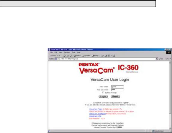
B. Login page
1) ID and password
To connect to a VersaCam, you must follow the Login procedures. If you key in a user’s ID and Password, you may access the viewer to monitor real-time images, and if you key in an administrator’s ID and password, you may access the Admin page.
The default user’s ID and password are set to ‘guest’, and the administrator may change them through the Admin page. Note that each ID and password may be composed of up to 9 letters.
2)Behind A Firewall
If the PC is connected to a network where a firewall is installed, the real time image may not be displayed properly because the video TCP port of VersaCam is blocked. The default video TCP port of a VersaCam (8080) is often blocked under a firewall. In this case, the real time image may be viewed by using the VersaCam’s Server Push Viewer that transmits video through a Web TCP port instead of the video TCP port.
To connect to the Server Push Viewer, click on the ‘Behind Firewall’ menu selection. Performance will likely be slower in this mode.
13 |
VersaCam IC-360 User’s Guide |
3) VersaCam IC Series Plug-in for Netscape Users
To see the VersaCam image using a Netscape browser, the user should first install the VersaCam Plug-in by clicking the VersaCam Plug-in menu. When you connect the VersaCam for the first time or you have an old Plug-in version, you will have to download the current Plug-in by clicking ‘Download VersaCam Plug In Now!’ You then click the ‘Grant’ and ‘Install’ buttons respectively.
4) VersaCam IC Series Active-X for MS Explorer Users
For an Internet Explorer User, Active-X Control is automatically installed when the user accesses the VersaCam. For Active-X installation on your PC, just click ‘Yes’ if you want to install the program. If you cannot see images, you should check if the Active-X Control file is installed properly. You may check the VersaCam Control (Active-X Control) file in the folder C:\Windows\Download Program Files. If the VersaCam Control file is not installed, try again to re-install it. If the Plug-in or Active-X program fails to be installed automatically, you may install it manually.
The installation will not take longer than 1 minute. Don’t click any buttons until the installation is complete.
5) FAQ
Questions and answers are provided In Appendix 2 for troubleshooting. If you have other questions that are not answered here, please contact your distributor or the Pentax Customer Service Department.
14 |
VersaCam IC-360 User’s Guide |

C. Viewing With The VersaCam IC-360
There are 3 real-time viewers available on the VersaCam homepage: the “Default Viewer”, the “720×468 Viewer” and the “Server Push Viewer.” An administrator may set any viewer as a first user interface. A connected user may monitor real-time images through the administrator-selected main viewer or select another.
1) Real-time monitoring through the default viewer
The viewer page is composed of three areas: 1) The real-time image screen, 2) The Java applet Pan/Tilt/Preset control panel, and 3) The video control section at the bottom of page.
(1) Useful Pop-up Menu on the Realtime monitoring screen
A small window including 5 functions appears when a user clicks the right mouse button over the displayed image. Users who have the authority can access functions such as ‘Image Info’, ‘Quality Box’, ‘Focus Sensitivity’, and ‘Image Quality’.
Video Information Setting
This page allows changing the color of the time shown on
the left top of the image, or choosing not to show the time at all.
Configuration of the High Quality Image Area
You can overcome insufficient network bandwidth by using this function. Click the right mouse button on any place on the picture and drag to select a desired area. By selecting only a portion of the image for high contrast, the remaining portion of the image is sent at low contrast and is highly compressed.
If you want to set a new quality area, click on ‘New QBOX’. Place and click your cursor where you want to start and then drag the mouse and click again where you want the box to stop. You can also use the existing area to focus again by clicking ‘Enable QBOX.’ ‘Disable QBOX’ cancels the function. The image-activated high-quality area function is as below.
The user may set the quality of the “low contrast area” with ‘Ambient Level’. If you select ‘Level 1’, the quality
15 |
VersaCam IC-360 User’s Guide |
Loading...