


OWNER’S GUIDE
ER90/100/200
HOME VENTILATION SYSTEMS
J. H. • Rev. 1-93 • Printed in U.S.A. • Form Number 69-0737B—1
WELCOME…
…to the world of efficient ventilation. Engineered and built for long, trouble-free operation, this Honeywell ER90/100/200 Home Ventilation System provides proper levels of ventilation with energy savings by transferring heat and moisture between the exhaust and fresh air streams. Your home will now be better protected from indoor pollutants such as formaldehyde, tobacco by-products, radon, moisture, combustion byproducts and carbon monoxide. With the Honeywell
Home Ventilation System you can expect to enjoy the benefits of a properly ventilated energy efficient home for years to come.
Features and benefits:
•Recover up to 85 percent of the total heating or cooling energy in the exhaust air.
•Reduce air conditioning load by up to 0.4 ton during air conditioning season.
•Operates condensation free. No drain required.
•Easy-to-clean energy transfer wheel assures years of trouble-free operation.

CONTENTS |
|
|
PAGE |
CONTROLS FOR YOUR HOME VENTILATION SYSTEM |
................... 2 |
OPERATING YOUR HOME VENTILATION SYSTEM .......................... |
3 |
GETTING THE MOST FROM YOUR HOME |
|
VENTILATION SYSTEM ................................................................... |
4 |
MAINTENANCE INSTRUCTIONS FOR THE HOME |
|
VENTILATION SYSTEM ................................................................... |
6 |
WARRANTY ......................................................................................... |
10 |
BENEFITS OF PERFECT CLIMATE™ AND THE HOME |
|
VENTILATION SYSTEM ................................................................. |
11 |
1 |
69-0737B—1 |
CONTROLS FOR YOUR HOME VENTILATION SYSTEM
Your Home Ventilation System comes equipped with a factory supplied control package consisting of:
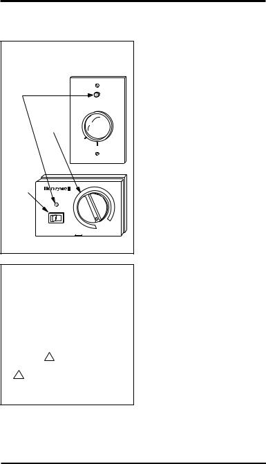
Fig. 1—Fresh air control for Home Ventilation System.
INDICATOR
LIGHT
FRESH AIR CONTROL
FRESH AIR
CONTROL MAX
KNOB 
|
|
|
OFF |
|
|
|
|
|
|
MIN |
|
|
|
|
|
ER90 |
|
RANGE |
|
|
|
|
|
SWITCH |
FRESH AIR CONTROL |
|
|
|
|
|
|
|
|
||
|
HI |
LO |
|
L |
O |
|
|
|
|
|
|
|
|
RANGE |
HI |
AUT O |
|
|
|
|
|
||
|
|
SELECT HI OR LO RANGE - ADJUST AIRFLOW |
|
||
M3333 |
ER100/200 REMOTE CONTROL |
||||
1.FRESH AIR CONTROL Controls the air flow rate in the system, allowing the homeowner to change the air flow rate as conditions in the home change. To select the desired air flow rate position, move the knob on the controller to the desired level. See Fig. 1.
2.DEHUMIDISTAT Select the desired inside
humidity level for the home. The dehumidistat will override the fresh air control and cause the Home Ventilation System to operate at high speed until humidity levels are reduced to the humidistat setting. At this point, the dehumidistat will turn off and airflows will return to the fresh air control setting. For summer operation, set dehumidistat to OFF position.
Fig. 2—Master switch on the Home Ventilation System cover.
|
|
|
|
|
|
|
|
OFF |
|
|
|
|
|
|
|
|
|
|
|
|
|
|
|
|
|
|
|
|
|
|
|
|
|
|
|
|
|
|
|
|
|
|
|
|
HI |
OFF LO |
|
|
ON |
||||
|
|
1 |
|
|
|
|
|
|
|
|
|
|
|
|
|
||
|
|
ER90 |
ER100/200 |
|||||
|
1 MASTER SWITCH IS ALSO |
|||||||
|
|
RANGE SWITCH. |
|
|
M3328 |
|||
3.MASTER SWITCH
This switch is located on the unit cover. The switch turns off the unit completely, disabling the fresh air control, dehumidistat and blowers. See Fig. 2.
2

OPERATING YOUR HOME VENTILATION SYSTEM
STEP 1
Set the master ON/OFF switch located on the Home Ventilation System to ON or LO position. The switch light should come on. The system will now operate whenever the fresh air control or dehumidistat is turned on.
STEP 2
Turn the fresh air control knob to start the unit blowers. The indicator light should light. The fresh air control varies the speed of the blower. This allows you options for the amount of ventilation. The Home Ventilation System is a balanced system; the amount of fresh air introduced into the house is always balanced with the amount of air exhausted from the house. Increase the ventilation rate if you feel the house is stuffy, or if there is an above average occupancy rate. In most applications, a midrange setting on the fresh air control will provide proper ventilation. On some units, you may also select a HI or LO range when adjusting ventilation.
STEP 3
When using a dehumidistat, set the dehumidistat to the desired humidity level. If your heating system has a powered humidifier, be sure the dehumidistat is set at least ten percent relative humidity above your humidistat. It may be necessary to lower the humidistat setting to avoid condensation in the winter. This ensures a proper humidity level in the home. Set dehumidistat to OFF position for summer operation.
STEP 4
Your system is now fully functional. Perform an occasional check to ensure that the exhaust and intake outlets for the unit are clear. You should check that intake outlets are not close to any source of contamination such as barbecues or automobile exhaust. If you find a source of contamination close, move it. Be sure to check that the exhaust air is not being directed to the intake air hood.
3 |
69-0737B—1 |

GETTING THE MOST FROM YOUR HOME VENTILATION SYSTEM
FRESH AIR CONTROL
The low voltage remote fresh air controls (ER100/200 only) allow convenient operation of the ventilation system from the living area of your home. The control performs the following four functions:
1.A two-position HI-LO range switch lets you place the ventilator into LO or HI speed range. Only certain models have this feature.
2.The control knob allows selection of continuous ventilation rates within the pre-selected HI or LO speed range.
3.This same knob is used to place the ventilator into the AUTO mode. In AUTO, the blower is operated by the dehumidistat and/or override switches that can be installed as options with your Home Ventilation System.
4.An indicator light above the HI-LO switch verifies operation of the unit.
MOISTURE CONTROL
Continual operation of the ventilation is recommended for optimum reduction of indoor air pollution and control of humidity. Increased moisture removal will always occur at maximum ventilation rates. This setting should be used when first occupying a newly built home to remove excess moisture from new wood, plaster, cement and other moisture absorbing construction materials. If your system is wired
to a dehumidistat, preselected moisture levels can be maintained automatically. Severe moisture conditions can be controlled with the sensible energy transfer wheel when the indoor air contains more moisture than the outdoor air.
REMOTE OVERRIDE SWITCH FUNCTIONS
Your ventilation system may incorporate one or more remotely located switches to activate bathroom ventilation, a dehumidistat, or any combination of these or other ventilation functions. A remote switch in the ON position will cause the ventilator to operate at high speed until the override switch is turned off. The ventilator will automatically return to its previous setting on the fresh air control. The remote override switch, in combination with the AUTO mode, is especially useful for intermittent bathroom exhaust when continuous ventilation is not required. Continuous operation is recommended except when the home is unoccupied, or when proper ventilation is provided by other means like open doors and windows.
4

FROST CONTROL
Some Home Ventilation System models have built-in automatic preheat frost control systems that allow the unit to operate in cold weather regions. Areas where the winter design temperature does not fall below 5° F [-15° C] will not require a preheater. The function of the frost control is to ensure that the intake air brought into the Home Ventilation System is not below 10° F [-12° C]. This ensures proper operation of the Home Ventilation System. Operation is indicated by the indicator light located on the Home Ventilation System cabinet next to the PRESS-TO-TEST button. The indicator light is on when the outdoor temperature is below 10° F [-12° C] or the TEST button is pressed. The preheat system is functioning if the indicator light comes on when the TEST button is pressed. Test the preheat system before the heating seasons starts each year. Follow the instructions on the cabinet for testing.
IMPORTANT: Release the TEST button as soon as the neon light comes on. Pressing the TEST button longer can cause overheating of the Home Ventilation System.
5 |
69-0737B—1 |
MAINTENANCE INSTRUCTIONS FOR THE HOME
VENTILATION SYSTEM
!CAUTION
Electric shock hazard.
Can cause personal injury or equipment damage.
Disconnect power supply before doing maintenance.
The Home Ventilation System must be maintained on a regular basis for the best efficiency. Honeywell recommends the Home Ventilation System to be cleaned and checked at least twice a year, preferably at the start of each heating and cooling season.
!CAUTION
Make sure the master switch is in OFF position before doing any maintenance.
Check and/or clean as follows:
Room Air Filter: Remove and wash this wire mesh filter to assure proper airflow in the unit. See Fig. 3. Only the ER90/100s have the room air filter.
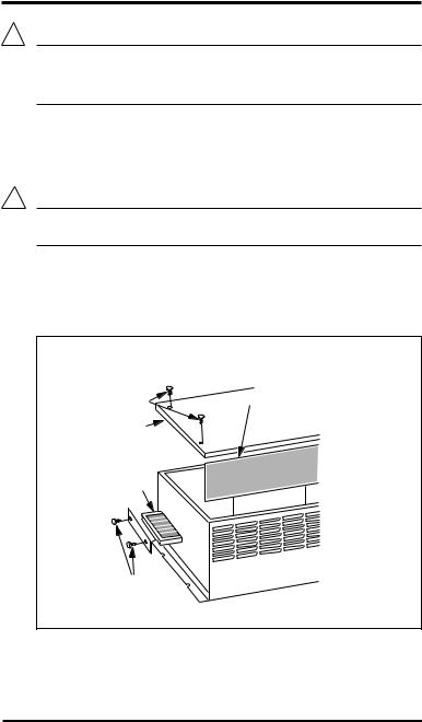
Fig. 3—ER90/100 stale air intake filter and fresh air filter location.
THUMB-
SCREWS STALE AIR
INTAKE FILTER
COVER
FRESH
AIR
INTAKE
FILTER
THUMB-
SCREWS
M3324
6
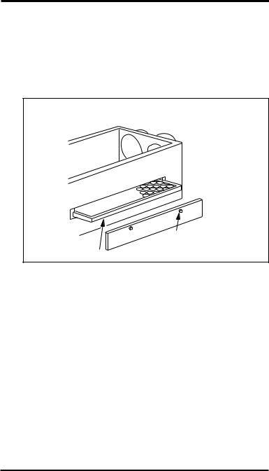
Fresh Air Filter: Replace the fresh air filter at least twice a year. To remove filter:
1.Unscrew access panel thumbscrews to remove the filter access panel. See Figs. 3 and 4.
2.Slide the fresh air filter out of the Home Ventilation System.
3.Check filter and replace if clogged.
4.Place the filter access panel back on the Home Ventilation System and tighten the thumbscrews.
Fig. 4—ER200 fresh air filter location.
 THUMB-
SCREWS
FRESH |
|
AIR FILTER |
M3323 |
Weather Caps: Check to ensure that the outside fresh air inlet and exhaust weather caps do not become clogged with debris like grass, leaves and snow.
Energy Transfer Wheel: Check the energy transfer wheel for build-up of dirt and debris.
NOTE: Energy transfer is not affected by stained surfaces.
To remove and clean the ER90/100s Energy Transfer Wheel:
1.Unscrew the screws holding the Home Ventilation System cover and remove the cover. See Fig. 5.
2.Take out the center divider.
3.Loosen the screw in the center of the wheel hub cap.
4.Rotate hub cap counterclockwise and remove.
5.Grasp hub with two fingers and take straight off the drive shaft.
IMPORTANT: Lift only by the hub.
7 |
69-0737B—1 |

5.Spray the energy transfer wheel thoroughly with household spray cleaner (Fantastic™ or equivalent). Rinse with warm water. Use a soft brush to remove stains between the plastic windings. Shake excess water from the wheel.
6.Replace the wheel on the drive shaft.
NOTE: Rotate the wheel counterclockwise until the pin in the shaft has engaged in the slot in the bottom of the hub. The end of the drive shaft and the face of the hub will be flush.
|
|
|
7. |
Put hub cap on, rotate |
Fig. 5—ER90/100 Energy Trans- |
|
in clockwise direction, |
||
fer Wheel and belts location. |
|
tighten screw. |
||
|
|
|
8. |
Install the center divider. |
ENERGY |
ENERGY TRANSFER |
|
9. |
Replace the Home |
TRANSFER |
WHEEL HUB CAP |
|
|
Ventilation System |
WHEEL |
|
|
|
|
|
|
|
|
cover and tighten the |
|
|
|
|
screws. |
|
|
BLOWER |
To remove and clean the |
|
|
|
ER200 Energy Transfer |
||
|
|
AND |
||
|
|
MOTOR |
Wheel: |
|
|
|
|
||
|
DRIVE BELT SET |
M3325 |
1. |
Unscrew the screws |
|
|
|
|
holding the ventilator |
|
|
|
|
door and open the door. |
Fig. 6—ER200 Energy Transfer |
2. |
Take out the center |
||
Wheel and belts location. |
|
|
divider. |
|
ENERGY |
|
|
3. |
Remove the belt from |
|
|
|
the rim of the wheel. |
|
TRANSFER WHEEL |
|
|
||
WHEEL DRIVE |
|
|
|
See Fig. 6. |
BELT |
|
|
4. |
Unscrew the screw in |
WHEEL DRIVE |
|
|
||
|
|
|
the center of the hub. |
|
PULLEY |
|
|
|
|
|
|
|
5. |
Use the rim of the wheel |
WHEEL DRIVE |
|
|
|
and lift the wheel |
MOTOR |
|
|
|
straight off the drive |
|
|
|
|
|
|
|
|
|
shaft. |
|
|
|
6. |
Spray the energy |
|
|
|
|
transfer wheel thor- |
|
|
|
|
oughly with household |
|
|
|
|
spray cleaner (Fantas- |
|
|
|
|
tic™ or equivalent). |
|
|
|
|
Rinse with warm water. |
|
|
M3322A |
|
Use a soft brush to |
|
|
|
|
remove stains between |
|
|
8 |
|
|
 Loading...