


Auto Flash
OPERATING MANUAL

Introduction
Thank you for purchasing the Auto-flash AF540FGZ II/ AF360FGZ II.
In addition to easy daylight sync photography with P-TTL auto, the AF540FGZ II/AF360FGZ II also allows wireless P-TTL auto photography and high-speed sync in combination with a digital single lens reflex camera or lens-interchangeable single lens digital camera.
Please read this operating manual before using this flash unit.
This operating manual applies to AF540FGZ II and AF360FGZ II.
The illustrations used in this operating manual are those of AF540FGZ II.
For Use with the Following Models:
645D, K-5II, K-5IIs, K-5, K-30, K-50, K-500, and K-r
When using the flash unit with the models listed above, the camera’s firmware needs to be updated to the latest version in order to use the LED beam as the AF-assist spot beam. (Refer to page 53.)
This update corrects the focus position deviation caused by the difference in wavelengths between the AF-assist spot beam of this flash unit and existing flash units.
The LED beam cannot be used as the AF-assist spot beam when using the flash unit with the digital single lens reflex cameras released before the K-7 and K-x. Set OFF for AF Spot Beam (Sb) in the function menu. (Refer to page 52.)
Firmware Download URL: http://www.ricoh-imaging.co.jp/english/support/download_digital.html
FOR THE SAFE USE OF YOUR FLASH UNIT
Although we have carefully designed this flash unit for safe operation, please pay special attention to items marked with the following symbols when using the flash unit.
 WARNING
This symbol indicates that violating this item could cause serious personal injuries.
CAUTION
This symbol indicates that violating this item could cause minor or medium personal injuries, or loss of property.
 is a symbol indicating items that are prohibited.
  is a symbol emphasizing a warning.
 WARNING
The flash contains electronic circuits that operate at high voltages. Do not attempt to disassemble the flash unit yourself, as there is danger of an electric shock.
If internal parts of the flash unit become exposed due to impact, etc., do not touch them as there is danger of an electric shock.
Do not expose the flash unit to water or moisture as there is danger of an electric shock.
1

 CAUTION
Do not use the flash and/or LED beam near a person’s eyes, as it may hurt them. Be particularly careful when using the flash around infants.
The following may lead to an explosion or fire.
λShorting the batteries
λExposing the batteries to flames
λDismantling the batteries
λRemove the sticker covering the battery
λAttempting to recharge non-rechargeable batteries
Remove the batteries from the camera immediately if they become hot or begin to smoke. Be careful not to burn yourself during removal.
2

Precautions for Your Flash Unit
λNever use organic solvents such as paint thinner, alcohol or benzine to clean the flash unit.
λAvoid leaving the flash unit for extended period in places where the humidity and temperature are very high such as in a car.
λBe careful not to subject the flash unit to strong vibrations, shock or pressure. Use a cushion to protect the flash unit when carrying it in a motorcycle, car, boat, etc.
λThe flash unit is designed to be water-proof and dust-proof. However, do not use the flash unit where it may be directly exposed to rain, water, etc.
λWhen using the flash unit off the camera, do not try to attach any metallic object to the electric contacts or to mount incompatible accessories. Otherwise, the P-TTL auto mechanism may be damaged or rendered inoperable.
λPeriodic checks are recommended every 1 to 2 years in order to maintain high performance. If the unit has not been used for an extended period of time, or is being readied for an important shoot, it is recommended that you take a test flash with the test button and test shoot with it. Test flash is also important to maintain optimum performance.
λAvoid contact with garbage, dirt, sand, dust, water, toxic gases, salt, etc. When the flash unit is subjected to rain or moisture, wipe it off with a dry cloth.
λWhen photographing black or white subjects, use exposure compensation.
λThe flash unit may become hot when discharges many times in succession, resulting in damage or malfunction.
λDo not attach any accessories such as the hot shoe grip which have the different number of electrical contacts.
λThe hot shoe of the camera incorporates flash signal contacts. Dirt, dust, or corrosion on the contacts may cause a malfunction.
λWe will not be held responsible for any accidents or damage, etc. caused due to the use of this product with cameras and accessories made by the other companies.
λThe LED beam of the unit is to assist shooting with a camera. Do not use the LED beam for other purposes.
3

νCautions Regarding Batteries
λThis flash unit uses four AA alkaline, lithium, or nickel metal hydride batteries. Do not use any other types of batteries. The flash unit may not be able to operate correctly or demonstrate sufficient performance, or the flash unit itself may generate heat, depending on the type of batteries used.
λAA alkaline and lithium batteries themselves are not rechargeable. Also, do not dismantle the batteries. Trying to recharge or dismantle the batteries may cause an explosion or leakage.
λWhen changing batteries, do not mix batteries of different types or capacities, or from different manufacturers.
λDo not insert the batteries with the positive (+) and negative (-) terminals the wrong way around. Incorrect insertion may lead to an explosion or fire.
λBattery performance may temporarily be hindered in low temperatures. Batteries should be kept warm in temperatures below freezing for proper performance.
λIf you do not intend to use the flash unit for an extended period of time, remove the batteries. Leaving them in may cause damage to the flash unit due to leakage etc.
λDo not short the batteries or dispose of the batteries in fire. Do not disassemble the batteries. The batteries could explode or catch fire.
λRemove the batteries from the flash unit immediately if they become hot or begin to smoke. Be careful not to burn yourself during removal.
4

Contents
Introduction......................................................................................... |
1 |
FOR THE SAFE USE OF YOUR FLASH UNIT.................................. |
1 |
Precautions for Your Flash Unit.......................................................... |
3 |
ν Cautions Regarding Batteries.................................................................... |
4 |
Overview of the Operating Manual..................................................... |
7 |
Names of Parts................................................................................... |
8 |
ν Parts of This Flash Unit.............................................................................. |
8 |
ν Major Bundled Items................................................................................ |
10 |
ν LCD Panel Indicator................................................................................. |
11 |
1. Getting Ready |
13 |
Inserting the Batteries....................................................................... |
13 |
Mounting to the Camera................................................................... |
15 |
Turning the Power On and Off.......................................................... |
16 |
Setting Button/Adjustment Dial Functions ........................................ |
18 |
Flash Coverage Angle...................................................................... |
21 |
2. Taking Pictures |
24 |
Using the Flash Modes..................................................................... |
24 |
ν P-TTL Auto Flash..................................................................................... |
25 |
ν Manual Flash............................................................................................ |
26 |
ν Multi Flash................................................................................................ |
27 |
ν Wireless Mode (P-TTL)............................................................................ |
28 |
ν Wireless Mode (Manual).......................................................................... |
29 |
ν Taking Pictures/Shooting Movies with LED Beam (LED Beam Mode).... |
30 |
Using the Sync Modes ...................................................................... |
31 |
ν Leading Curtain Sync Mode...................................................................... |
31 |
ν Trailing Curtain Sync Mode....................................................................... |
31 |
ν High-Speed Sync Mode............................................................................ |
32 |
ν Contrast Control Sync Mode..................................................................... |
34 |
Using the Function Menu .................................................................. |
36 |
About the Function Menu.................................................................. |
37 |
Setting Items in the Function Menu................................................... |
38 |
Advanced Functions.......................................................................... |
40 |
ν Wireless Mode.......................................................................................... |
40 |
ν Slave Flash............................................................................................... |
48 |
ν Slave Mode Setting................................................................................... |
50 |
ν Bounce Flash............................................................................................ |
51 |
ν AF Spot Beam with LED........................................................................... |
52 |
ν Wide-Angle Panel..................................................................................... |
54 |
ν Test Flash................................................................................................. |
54 |
ν Connecting with the Extension Cord......................................................... |
55 |
ν Precautions When Photographing with a Slave Flash.............................. |
55 |
3. Appendix |
56 |
Flash Effective Range....................................................................... |
56 |
ν Calculating the Flash Effective Range...................................................... |
56 |
ν Guide Number (GN).................................................................................. |
57 |
Optional Accessories......................................................................... |
61 |
Specifications.................................................................................... |
62 |
Warranty Policy................................................................................. |
64 |
5
6

Overview of the Operating Manual
The operating manual includes the following chapters.
1 Getting Ready
This chapter explains about getting ready to take pictures after you purchase the flash unit.
Be sure to read this chapter before you start taking pictures or operating the flash unit.
2 Taking Pictures
This chapter explains how to take pictures and how to set the functions for taking pictures.
3 Appendix
The appendix includes materials, data tables, and specifications.
1
2
3
7

Names of Parts
ν Parts of This Flash Unit
1Bounce angle adjustment
2LCD panel
3Flash mode button
4Sync mode button
5LED button/LED Ready lamp
6Test button/Ready lamp
7Zoom button
8LCD panel illumination button/Function button
9Power switch
0 Setting button a Adjustment dial
8
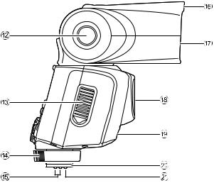
bBounce lock release button
cBattery chamber cover
dLocking lever
eFlash signal contacts
fWide-angle panel
gFlash head
hLED emitter
iWireless slave sensor
jShoe bracket
kShoe lock pin
9
|
ν Major Bundled Items |
|
1 Stand |
|
2 Case |
Opening of the stand |
3 Operating manual (this manual) |
4 Certification |
|
|
Slide the hot shoe bracket into the opening of the stand. |
• You cannot attach the off-camera shoe adapter F to the bundled stand.
• When attaching the flash unit to the stand, do not tighten the locking levertoofar.Tightening too farmaycausethelocking lever to not lock sufficiently when the flash unit is removed from the stand and attached to the hot shoe of the camera.
Stand
10
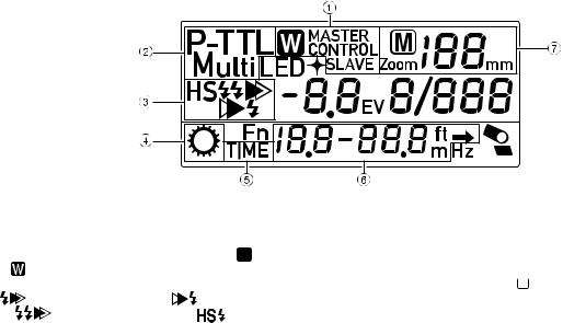
ν LCD Panel Indicator
1Wireless mode indicator: MASTER∏CONTROL∏SLAVE
2Flash mode indicator: P-TTL∏M∏Multi∏  (P-TTL) ∏ (Manual)
3Sync mode indicator:
|
(Leading curtain sync)∏ |
(Trailing curtain sync) |
∏ |
(Contrast control sync)∏ |
(High-speed sync) |
4 Adjustment dial indicator
5 Number of flashes
6Effective flash range indicator:
Minimum distance – Maximum distance (in P-TTL mode) Correct exposure distance (in manual mode)
7Zoom indicator:
auto (Zoom)∏manual (  Zoom) XXX mm= 13, 16, 19, 24, 34, 48, 58 (K series (APS-C))
25, 30, 35, 43, 62, 87, 106 (645D) 3, 4, 5, 6, 9, 13, 15 (Q series)
11
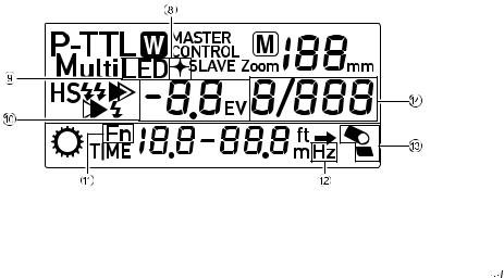
8Catchlight indicator
9LED beam mode
0 Flash output compensation indicator: -4.0 to +2.0 levels, (auto (A), 1/3, 1/2 step)
aFunction menu indicator
bFlash frequency indicator
cBounce flash indicator
dFlash output adjustment indicator: X / XXX
•In poorly lit locations where the LCD panel cannot be seen,
pressing the LCD panel illumination button (

 ) will illuminate the LCD panel for about 10 seconds. Pressing it again will turn off the illumination.
12
1
1. Getting Ready
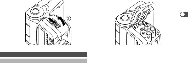
Inserting the Batteries
1Slide the battery chamber cover as shown in the figure to open.
2Insert four AA batteries, making sure the plus/minus markings (+, -) match the diagram inside the battery chamber cover.
2
1
Types of Batteries
This flash unit uses four AA batteries of the same type, as shown below.
-Alkaline battery (LR6)
-Lithium battery (FR6)
-Nickel-Metal Hydride battery (Ni-MH)
(Nickel manganese (Ni-Mn) and nickel cadmium (Ni-Cd) batteries cannot be used.)
•For information about recycling times and total number of flashes, refer to “Specifications” on page 62.
•If the indicators on the LCD panel or the Ready lamp does not light up, the batteries may be exhausted or not inserted correctly. Verify the orientation of the batteries or, if the indicators and the Ready lamp still do not light up, replace them with new batteries.
13

•If you let the flash unit discharge successively using lithium batteries,thebatterieswilloverheat,activatingasafetycircuit that temporarily disables the flash unit. If this occurs, rest the
1 flash unit so that the temperature of the batteries returns to normal.
•The blinking low battery indicator shown in the illustration appears on the LCD panel when the batteries are exhausted. Replace all the four batteries with new ones.
14
1
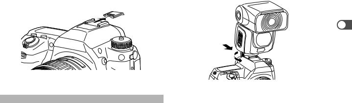
Mounting to the Camera
1Remove the hot shoe cover from the camera.
2Attach the flash unit to the camera.
1Facing the LCD panel, turn the locking lever of the flash unit to the left.
2Slide the hot shoe bracket of the flash unit into the camera’s hot shoe from the back of the camera forward.
3Facing the LCD panel, turn the locking lever of the flash unit to the right to lock it.
•Whenreleasingtheflashunit,besuretofacetheLCD panelandturnthelockinglevertotheleft,thenloosen the shoe lock pin. Otherwise, the hot shoe will be damaged.
2
1
•Do not hold the flash unit when attached to the camera. Otherwise the camera may drop and be damaged.
15
1
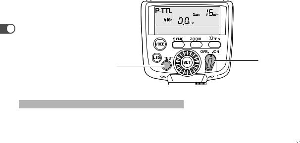
Power switch
Ready lamp
Turning the Power On and Off
1Turn the camera on, then turn on the unit’s power switch (ON).
•The Ready lamp will light up when the flash is charged.
2Turn off the unit’s power switch (OFF).
•If charging time takes more than 20 seconds, the batteries have been exhausted and should be replaced withnewbatteries.Iftheflashunitisusedwithexhausted batteries, the settings may return to their default configuration.
Auto Power Off Function
When the flash unit is left unused for about 3 minutes with the power switch set to the (ON) position, it automatically switches off to save the power.
1Turn on the power switch (ON).
2Press and hold the function button (


 ).
).
3Rotate the adjustment dial to display PH on the LCD panel.
4Press the setting button (SET) to blink PH1 or PH2.
PH1: Enables the auto power off function. (Default setting) PH2: Disables the auto power off function.
5Rotate the adjustment dial to select PH1 or PH2.
16

6 Press the setting button (SET) to complete the setting.
• |
To exit the function menu, press and hold the function |
|
|
|
button ( |
). |
|
• |
Refer to “Using the Function Menu” (page 36) for details |
1 |
|
|
on the function menu. |
|
|
•Inwirelessmode,thepowerwillturnoffafterabout1hour of non-operation (in SLAVE mode only).
Quick Power On Function
If the flash unit is mounted on autofocus cameras, press the shutter release button half way down to turn on the power.
17
1 |
2 |
1
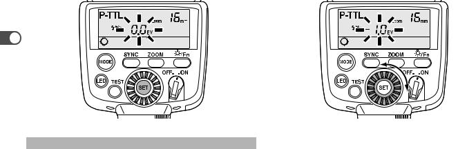
Setting Button/Adjustment Dial Functions
With the setting button (SET) and adjustment dial, you can configure the settingsof flash modes orLED beammode, such as flash output, etc. Refer to page 20 for each setting item, and also “Using the Function Menu” (page 36) when using the function menu.
1
2
3
Turn on the power switch (ON).
Pressthesettingbutton(SET)toblinkthenumberyouwant to set.
Rotate the adjustment dial to set the blinking number.
18

3 
1
4Press the setting button (SET) again to complete the setting. Adjust the other setting items using the same procedure.
•If you want to use multiple flash units set to P-TTL and adjust the amount of light at the same time, use the camera’s exposure compensation.
19
Setting Items in Flash Modes
|
|
|
Sync mode |
|
Wireless mode |
|
Flash output |
|
Number |
Flash |
||
|
Flash mode |
Leading |
Trailing |
Contrast |
High- |
|
|
|
Flash output |
offlashes |
frequency |
|
|
MASTER |
CONTROL |
SLAVE |
compensation |
||||||||
1 |
|
|
(Multi) |
(Multi) |
||||||||
|
curtain |
curtain |
control |
speed |
|
|
|
|
|
|||
|
P-TTL (auto) |
z |
z |
z |
z |
– |
– |
– |
-4.0to+2.0 |
– |
– |
– |
|
|
|
|
|
|
|
|
|
|
|
|
|
|
M (Manual) |
|
|
|
|
|
|
|
|
1/1, 1/2, 1/4, 1/8, |
|
|
|
|
z |
– |
– |
– |
– |
– |
– |
– |
1/16, 1/32, 1/64, |
– |
– |
|
|
|
|
|
|
|
|
|
|
1/128, 1/256 |
|
|
|
|
|
|
|
|
|
|
|
|
|
|
|
|
Multi (Multi flash) |
|
|
|
|
|
|
|
|
1/4, 1/8, 1/16, |
|
|
|
|
z |
– |
– |
– |
– |
– |
– |
– |
1/32, 1/64, |
2 to 100 |
1 to 200 |
|
|
|
|
|
|
|
|
|
|
1/128, 1/256 |
|
|
|
|
|
|
|
|
|
|
|
|
|
|
|
|
WIRELESS (P-TTL) |
z |
– |
z |
z |
z |
z |
z |
-4.0to+2.0 |
1/1, 2/3, 1/2, 1/3 |
– |
– |
|
|
|
|
|
|
|
|
|
|
|
|
|
|
WIRELESS (M) |
|
|
|
|
|
|
|
|
1/1, 1/2, 1/4, 1/8, |
|
|
|
|
z |
– |
– |
– |
– |
– |
z |
– |
1/16, 1/32, 1/64, |
– |
– |
|
|
|
|
|
|
|
|
|
|
1/128, 1/256 |
|
|
|
|
|
|
|
|
|
|
|
|
|
|
|
|
LED beam light output |
– |
– |
– |
– |
– |
– |
– |
– |
Auto, 1/1, 1/2, |
– |
– |
|
|
1/4, 1/8, 1/16 |
||||||||||
|
|
|
|
|
|
|
|
|
|
|
|
|
|
|
|
|
|
|
|
|
|
|
|
|
|
20
 Loading...