


Pentair TR 100HD, TR 100, TR 140C, TR 60, TR 140C-3 User Manual
...Triton® Fiberglass Sand Filters
Models:
TR 40, TR 50, TR 60, TR 100, TR 140
TR 100HD, TR 100C, TR 140C
TR 100C-3, TR 140C-3 and
Model: TR 60 with 


Technology™
Triton C-3 - Commercial
Triton C - Commercial
Triton HD - Commercial
Triton II - Residential
Installation & User's Guide
IMPORTANT SAFETY INSTRUCTIONS
READ AND FOLLOW ALL INSTRUCTIONS
SAVE THESE INSTRUCTIONS

Customer Service
If you have questions about ordering Pentair replacement parts, and pool products, please use the following contact information:
Customer Service / Technical Support (8 A.M. to 5 P.M. — Eastern and Pacific Times)
Phone: (800) 831-7133
Fax: (800) 284-4151
Sanford, North Carolina (8 A.M. to 5 P.M. — Eastern Time)
Phone: (919) 566-8000
Fax: (919) 566-8920
Moorpark, California (8 A.M. to 5 P.M. — Pacific Time)
Phone: (805) 553-5000 (Ext. 5591)
Fax: (805) 553-5515
Web site
visit www.pentairpool.com or www.sta-ritepool.com to find information about Pentair products
R
M E M B E R
N A T I O N A L
SPA & POOL
INSTITUTE
© 2007 Pentair Water Pool and Spa, Inc. All rights reserved.
This document is subject to change without notice.
1620 Hawkins Ave., Sanford, NC 27330 • (919) 566-8000
10951 West Los Angeles Ave., Moorpark, CA 93021 • (805) 553-5000
Trademarks and Disclaimers: ClearPro is a trademark of Pentair Water Pool and Spa, Inc. The Pentair Pool Products logo and Triton are registered trademarks of Pentair Water Pool and Spa, Inc. Other trademarks and trade names may be used in this document to refer to either the entities claiming the marks and names or their products. Pentair Water Pool and Spa, Inc. disclaims any proprietary interest in trademarks and trade names other than its own.
P/N 154901 Rev. C 5/21/07

i
|
Table of Contents |
Important Safety Precautions.............................................................................................. |
ii |
Section 1: Introduction ..................................................................................................... |
1 |
Triton® Fiberglass Sand Filters Overview ................................................................ |
1 |
General Features..................................................................................................... |
2 |
Section 2: Installation ....................................................................................................... |
3 |
Installing the Triton® Fiberglass Sand Filter.............................................................. |
3 |
How your Triton® Filter works .................................................................................. |
3 |
Installing the Triton® Filter Threaded and Oval Closures .......................................... |
5 |
Initial Start-Up.......................................................................................................... |
6 |
Section 3: Maintenance ..................................................................................................... |
7 |
Triton® Filter Care..................................................................................................... |
7 |
Triton® Filter Cleaning .............................................................................................. |
7 |
Triton® Filter Backwash Procedure.......................................................................... |
8 |
Chemical Cleaning Procedure ................................................................................. |
9 |
Winterizing your Triton® Filter ................................................................................... |
9 |
Section 4: Troubleshooting .............................................................................................. |
10 |
Section 5: Replacement Parts .......................................................................................... |
12 |
Triton® Filter Pressure Drop Curve .......................................................................... |
12 |
Installing Multiple Triton® Filters (Tandem Filter Piping Kits) ............................................ |
12 |
Triton® II, TR60 ClearPro & Triton® HD Replacement Parts |
.....................................13 |
Triton® 100C & 140C Replacement Parts ................................................................ |
16 |
Triton® 100C-3 & 140C-3 Replacement Parts ......................................................... |
18 |
Après – Filtres à Sable en Fibre de Verre Triton® |
|
Después – Filtros de Arena de Fibra de Vidrio Triton® |
|
Triton® Fiberglass Sand Filter Installation and User’s Guide
ii
IMPORTANT SAFETY PRECAUTIONS
 Important Notice:
This guide provides installation and operation instructions for the Triton® Series Fiberglass Sand Filters. Consult Pentair Water with any questions regarding this equipment.
Attention Installer: This guide contains important information about the installation, operation and safe usage of this product. This information should be given to the owner and/or operator of this equipment after installation or left on or near the filter.
Attention User: This manual contains important information that will help you in operating and maintaining this filter. Please retain it for future reference.
WARNING —Before installing this product, read and follow all warning notices and instructions which are included. Failure to follow safety warnings and instructions can result in severe injury, death, or property damage. Call (800) 831-7133 for additional free copies of these instructions.
Consumer Information and Safety
The Triton® Series Sand Filters are designed and manufactured to provide many years of safe and reliable service when installed, operated and maintained according to the information in this manual and the installation codes referred to in later sections. Throughout the manual, safety warnings and cautions are identified by the “  “ symbol. Be sure to read and comply with all of the warnings and cautions.
 WARNING — THIS FILTER OPERATES UNDER HIGH PRESSURE
When any part of the circulating system, (e.g., closure, pump, filter, valve(s), etc.), is serviced, air can enter the system and become pressurized. Pressurized air can cause the top closure to separate which can result in severe injury, death, or property damage. To avoid this potential hazard, follow these instructions:
1.If you are not familiar with your pool filtering system and/or heater:
a.Do NOT attempt to adjust or service without consulting your dealer, or a qualified pool technician.
b.Read the entire Installation & User’s Guide before attempting to use, service or adjust the pool filtering system or heater.
2.Before repositioning valve(s) and before beginning the assembly, disassembly, or any other service of the circulating system: (A) Turn the pump OFF and shut OFF any automatic controls to ensure the system is NOT inadvertently started during the servicing; (B) open the manual air bleeder valve; (C) wait until all pressure is relieved.
3.Whenever installing the filter closure FOLLOW THE FILTER CLOSURE WARNINGS EXACTLY.
4.Once service on the circulating system is complete FOLLOW INITIAL START-UP INSTRUCTIONS EXACTLY.
5.Maintain circulation system properly. Replace worn or damaged parts immediately, (e.g., closure, pressure gauge, valve(s), o-rings, etc).
6.Be sure that the filter is properly mounted and positioned according to instructions provided.
Triton® Fiberglass Sand Filter Installation and User’s Guide
iii
IMPORTANT SAFETY PRECAUTIONS (continued)
 WARNING — This filter must be installed by a licensed or certified electrician or a qualified pool serviceman in accordance with the National Electrical Code and all applicable local codes and ordinances. Improper installation could result in death or serious injury to pool users, installers, or others and may also cause damage to property.
Always disconnect power to the pool circulating system at the circuit breaker before servicing the filter. Ensure that the disconnected circuit is locked out or properly tagged so that it cannot be switched on while you are working on the filter. Failure to do so could result in serious injury or death to serviceman, pool users or others due to electric shock.
WARNING —Do not operate the filter until you have read and understand clearly all the operating instructions and warning messages for all equipment that is a part of the pool circulating system. The following instructions are intended as a guide for initially operating the filter in a general pool installation. Failure to follow all operating instructions and warning messages can result in property damage or severe personal injury or death.
WARNING —To reduce the risk of injury, do not permit children to use this product unless they are closely supervised at all times.
WARNING —Due to the potential risk that can be involved it is recommended that the pressure test be kept to
the minimum time required by the local code. Do not allow people to work around the system when the circulation system is under pressure test. Post appropriate warning signs and establish
a barrier around the pressurized equipment. If the equipment is located in an equipment room, lock the door and post a warning sign.
Never attempt to adjust any closures or lids or attempt to remove or tighten bolts when the system is pressurized. These actions can cause the closure to blow off and could cause severe personal injury or death if they were to strike a person.
WARNING —Never exceed the maximum operating pressure of the system components. Exceeding these
limits could result in a component failing under pressure. This instantaneous release of energy can cause the closure to blow off and could cause severe personal injury or death if they were to strike a person.
Triton® Fiberglass Sand Filter Installation and User’s Guide

iv
This page is blank.
Triton® Fiberglass Sand Filter Installation and User’s Guide
1
Section 1
Introduction
Triton® Fiberglass Sand Filters Overview
Triton® II Sand Filters
The #1 sand filter in the world
Triton II is the result of over 40 years of product evolution and refinement. It has set the industry standard for effectiveness, efficiency, long runs between service, and providing years of dependable, low maintenance operation.
Triton II features a special internal design that keeps the sand bed level, ensuring even water flow, and resulting in the most efficient filtration possible.
The best reputation in the industry for all the right reasons
Besides its superior filtration performance, Triton II delivers a level of dependability and ease of operation and maintenance for a track record that’s unsurpassed. Every design detail has been refined to make Triton II the industry standard.
Triton® C and Triton® C-3 Commercial Sand Filters
This filter series features multiple diverters for increased filtration rates in commercial applications up to 20 GPM/Sq. Ft.
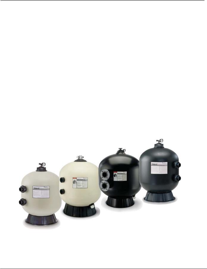
Triton® HD Side Mount Sand Filters
All the same great performance and features of the original Triton’s with maximum operating pressure of 75 psi for those special high pressure installations such as single pump in-floor cleaning systems.
Triton HD - Commercial
Triton C-3 - Commercial
Triton C - Commercial
Triton II - Residential
Triton® Fiberglass Sand Filter Installation and User’s Guide

2
General Features
Triton® II
•Time-proven internal design ensures that all water receives maximum filtration for crystal clear results
•GlasLok™ process creates a one-piece, fiberglass reinforced tank with a UV-resistant coating for years of dependable, corrosion-resistant service
•Flow system design controls filtration quality and ensures maximum run times between backwashing to save you time
Triton® C and Triton® C-3
•Maximum Operating Pressure 50 psi
•Full 2 in. drain
•8 in. opening for easy access to sand bed
•The Triton C-3 features standard 3 in. flange connections
•TR100C & TR140C models are available in black or almond
•TR100C-3 & TR140C-3 models are available in black only
Triton® HD
•Maximum Operating Pressure 75 psi
Additional Features:
•Combination sand and water drain speeds servicing and winterizing
•All internal parts are threaded for ease of maintenance
•Swing-away water diffuser allows instant access to sand and all internal parts
•NSF-Listed
Triton® Fiberglass Sand Filter Installation and User’s Guide

3
Section 2
Installation
Note: Before installing this product, read and follow all warning notices and instructions starting on page ii.
Installing the Triton® Fiberglass Sand Filter
Only a qualified service person should install the Triton Fiberglass Sand Filter. This filter is designed and intended for use to filter water.
Triton® Introduction
The following general information describes how to install the Triton Fiberglass Sand Filter. This filter operates under pressure and if assembled improperly or operated with air in the water circulation system, the top closure can separate and result in an accident causing property damage or serious bodily injury. A warning label has been affixed to the top of the filter and should not be removed. Keep safety labels in good condition and replace if missing or illegible.
How your Triton® Filter works
Your high rate sand filter is designed to operate for years with a minimum of maintenance and when installed, operated and maintained in accordance with these instructions, it will provide years of trouble free operation.
Dirt is collected in the filter as the water flows through the control valve at the side of the filter and is directed into the top bulkhead. Dirty water flows into the diffuser at the top of the tank and is directed downward into the top surface of the filter sand bed. The dirt is collected in the sand bed and the clean water flows through the laterals and lower piping at the bottom of the filter up into the lower bulkhead. The flow then goes into the control valve at the side of the filter. Clean water is returned through the piping system into the pool.
The pressure will rise and the flow to the pool will be lowered as the dirt is collected in the filter. Eventually, the filter will become so plugged with dirt that it will be necessary to perform the backwash procedure. It is important to know when to backwash the filter. Backwashing is discussed further under the subsequent sections of this guide.
Please note that a filter removes suspended matter and does not sanitize the pool. The pool water must be sanitized and the water must be chemically balanced for sparkling clear water. Your filtration system should be designed to meet your local health codes. As a minimum, you must be sure that your system will turn over the total volume of water in your pool at least two to four times in a twenty-four hour period.
Refer to Table 1 for Filter Operation Data.
Table 1.
|
FILTER |
FLOW RATE |
|
TURNOVER CAPACITY (Gallons) |
|
|
|
|
|
|
|
||
FILTER MODEL |
|
|
|
(Based on 20 GPM / Sq. Ft.)* |
|
|
|
AREA |
*(GPM) |
|
|
||
|
|
|
|
|
||
MODEL |
|
@20 GPM/FT2 |
|
|
|
|
|
(Sq. Ft.) |
4 TURNS PER DAY |
3 TURNS PER DAY |
2.4 TURNS PER DAY |
2 TURNS PER DAY |
|
|
|
|
||||
|
|
|
|
|
|
|
TR40 |
1.92 |
38 |
13,680 |
18,240 |
22,800 |
27,360 |
|
|
|
|
|
|
|
TR50 |
2.46 |
49 |
17,640 |
23,520 |
29,400 |
35,280 |
|
|
|
|
|
|
|
TR60 |
3.14 |
63 |
22,680 |
30,240 |
37,800 |
45,360 |
|
|
|
|
|
|
|
TR60 ClearPro |
3.14 |
63 |
22,680 |
30,240 |
37,800 |
45,360 |
|
|
|
|
|
|
|
TR100 |
4.91 |
74 |
26,640 |
35,520 |
44,400 |
53,280 |
|
|
|
|
|
|
|
TR100HD |
4.91 |
98 |
35,280 |
47,040 |
58,800 |
70,560 |
|
|
|
|
|
|
|
TR100C/TR100C-3 |
4.91 |
98 |
35,280 |
47,040 |
58,800 |
70,560 |
|
|
|
|
|
|
|
TR140 |
7.06 |
106 |
38,160 |
50,880 |
63,600 |
76,320 |
|
|
|
|
|
|
|
TR140C/TR140C-3 |
7.06 |
141 |
50,760 |
67,680 |
84,600 |
101,520 |
|
|
|
|
|
|
|
|
|
*TR100 AND TR140 ARE BASED ON 15 GPM/SQ. FT. |
|
|||
Triton® Fiberglass Sand Filter Installation and User’s Guide

4
 WARNING — Failure to operate your filter system or inadequate filtration can cause poor water clarity obstructing visibility in your pool and can allow diving into or on top of obscured objects which can cause serious personal injury or drowning.
Clear water is the result of proper filtration as well as proper water chemistry. Pool chemistry is a specialized area and you should consult your local pool service specialist for specific details. In general, proper pool sanitation requires a free chlorine level of 1 to 3 PPM and a pH range of 7.2 to 7.6.
 WARNING — Filters should never be tested or subjected to air or gas under pressure. All gases are compressible and under pressure create a danger. Severe bodily injury or property damage could occur if the filter is subjected to air or gas pressure.
1.Checkcartonforanyevidenceofdamageduetoroughhandlinginshipment.Ifcartonoranyfiltercomponents are damaged, notify the freight carrier immediately.
2.Carefully remove the accessory package and the filter tank from the carton.
3.Mount the filter on a permanent slab, preferably concrete poured in a form or on a platform constructed of concrete block or brick. DO NOT use sand to level the filter or for the pump mounting, as it will wash away.
4.Providespaceandlightingforroutinemaintenanceaccess.Donotmountelectricalcontrolsoverthefilter.One needstobeabletostandclearofthefilterwhenstartingthepump.Minimumspacerequirementsmaybefound on the large nameplate on the filter.
5.Position filter so that the port locations are in the desired final positions. Follow valve installation procedures.
6.If you have a Multiport Valve, assemble the valve to the tank, being sure the o-ring on the valve fittings are inplaceandareclean.Usealubricant,appliedlightly,suchassiliconegrease,Dow#33,#40orGE300or623, or similar product on o-rings and o-ring grooves prior to assembly.
7.If you have a two position slide valve, align the valve with the tank so that the handle is toward the top of the tank, push valve into ports and turn the valve nuts snugly on the tank fittings. It is not necessary to cinch the valve nuts to the tank fitting beyond hand tightness.
8.The shipping straps used to support the TR100C-3, TR140C and the TR140C-3 multi-diffuser should be removed before loading sand and gravel in the filter.
9.Sand specifications – be certain the proper sand is used as described in Table 2. Before pouring the sand into the filter, look inside and check the lower under-drain for broken or loose laterals (or fingers), which may have been accidentally damaged by rough handling during shipment. Replace any broken parts if necessary.
NOTE: The free board distance is the most important variable and should be maintained. Sand density will vary and therefore sand amount is given as a reference.
Table 2.
|
|
|
FILTER MEDIA† |
|
|
|
|
|
|
|
|
|
|
|
|
|
||
|
|
|
|
|
|
|
|
|
|
|
|
|
|
|
|
|||
|
|
ALL |
(POUNDS) |
|
|
|
|
|
|
|
|
|
|
|
|
|
|
|
|
FREE BOARD |
SAND* |
|
|
|
|
|
|
|
|
|
"X" |
|
|
|
|
FREE BOARD |
|
MODEL |
"X" |
(POUNDS) |
PEA GRAVEL ‡ |
|
SAND |
|
|
|
|
|
|
|
|
|
|
|||
|
|
|
|
|
|
|
|
|
|
|
|
|
|
|
||||
TR40 |
8 1/4" |
175 |
50 |
|
125 |
|
|
|
|
|
|
|
|
|
|
|||
|
|
|
|
|
|
|
|
|
|
|
|
|
|
|||||
|
|
|
|
|
|
|
|
|
|
|
|
|
|
|
|
|
|
|
TR50 |
9 3/4" |
225 |
50 |
|
175 |
|
|
|
|
|
|
|
|
|
|
|
|
|
|
|
|
|
|
|
|
|
|
|
|
|
ALL |
|
|
SAND |
|||
TR60 |
10 1/2" |
325 |
50 |
|
275 |
|
|
|
|
|
|
|
|
|||||
|
|
|
|
|
or |
|||||||||||||
|
|
|
|
|
|
|
|
|
|
|
|
|||||||
TR60 ClearPro |
10 1/2" |
325 |
50 |
|
275 |
|
|
|
|
|
|
|||||||
|
|
|
|
|
|
|
|
|
|
|
|
|||||||
|
|
|
|
|
|
|
|
|
|
|
|
|
|
& GRAVEL |
||||
TR100 |
11 1/4" |
600 |
150 |
|
450 |
|
|
|
|
|
|
SAND |
||||||
|
|
|
|
|
|
|
|
|
|
|
|
|
|
|
|
|
|
|
TR100HD |
11 1/4" |
600 |
150 |
|
450 |
|
|
|
|
|
|
|
|
|
|
|
|
|
|
|
|
|
|
|
|
|
|
|
|
|
|||||||
|
|
|
|
|
|
|
|
|
|
|
|
|
|
|
|
|
|
|
TR100C-3 |
11 1/4" |
600 |
150 |
|
450 |
|
|
|
|
|
|
|
|
|
|
|
|
|
|
|
|
|
|
|
|
|
|
|
|
|
|
|
|||||
|
|
|
|
|
|
|
|
|
|
|
|
|
|
|
|
|
|
|
TR140 |
13 1/2" |
925 |
275 |
|
650 |
|
|
|
|
|
|
|
|
|
|
|
|
|
|
|
|
|
|
|
|
|
|
|
|
|
|
|
|
|
|
|
|
TR140C-3 |
13 1/2" |
925 |
275 |
|
650 |
|
|
|
|
|
|
|
|
|
|
|
|
|
|
|
|
|
|
|
|
|
|
|
|
|
|
|
|
|
|
|
|
† Media required to meet NSF requirements.
‡Pea Gravel to be 1/4” to 1/8” diameter.
*Sand to be No. 25 standard silica (uniformity coefficient not greater than 1.75) .018-.020 in diameter particle size.
Triton® Fiberglass Sand Filter Installation and User’s Guide
5
 WARNING — Failure to position the Automatic Air Vent inside of the Closure will allow excessive trapped air to accumulate in the filter. Trapped air and the closure not properly closed can cause the closure to blow off and could cause severe bodily injury and/or property damage.
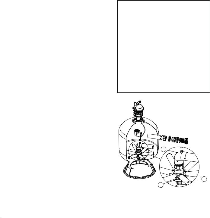
10.Pivot the diffuser out of the center of the tank on the TR40, 50, 60, TR60 ClearPro, 100 & 140 by rotating the diffuser assembly counter clockwise. (NOTE: The multi-diffuser assembly should not be moved on models TR100C,TR100C-3andTR140C,TR140C-3.Afterinstallingthefiltermediaasdescribedbelow,checktomake sure the tops on the diffusers are parallel to the top of the sand bed.) Fill the tank about half full of water. Pour pea gravel first (if used) and then the sand into the top of the filter at a slow rate so that the impact of the filter media does not damage the laterals. See Table 2 for the proper amounts of sand and gravel. Fill filter to the proper level to maintain freeboard, as shown in Table 2. Pivot the diffuser assembly back to its vertical position if it was moved. Be certain the automatic air vent is protruding into the top of the closure as indicated below in Figure 1. Ensure that the automatic air vent is in the center of the filter closure. Wash away all sand around the threaded opening at the top of the tank.
 WARNING —For Threaded Closures
Use care when installing closure. The closure should turn freely in the filter, if resistance to closure insertion is felt, then slowly remove the closure by turning counter-clockwise. The starting thread of the tank and closure must engage properly in order to secure the closure. Do not cross-thread closure.
Failure to install the closure properly can cause the closure to blow off and could cause severe bodily injury and/or property damage.
 WARNING —For Oval Closures
Use care when installing closure. The closure should be inserted into the tank by placing the small diameter of the oval closure into the larger diameter of the tank opening. Insert the side of the closure that does not have the pressure gauge and air bleeder first. The closure will need to be inserted at a 30° angle. Once the closure is inside the tank, it can be rotated 90° and lifted up to seal the tank. The aluminum bridge with load spring can then be placed over the closure bolt and the hand knob tightened to load the closure properly. The knob should be tightened by hand only. DO NOT USE A WRENCH TO TIGHTEN THE KNOB. You could damage the tank or closure and cause a failure by using a wrench. Failure to install the closure properly can cause the closure to blow off and could cause severe bodily injury or property damage.
NEVER ATTEMPT TO TIGHTEN OR LOOSEN THE CLOSURE WITH THE PUMP RUNNING. Failure to follow this instruction can result in the closure blowing off and causing severe bodily injury or property damage.
11.Assemble the pressure gauge and bleeder valve to the closure lid. Clean the lid o-ring and lubricate with silicone grease such as Dow #33, 40 or GE 300, 623 lubricant. Place the closure lid on the filter and tighten, making certain the air vent is up inside the dome of the closure.
12.With the plastic wrench, provided with the filter, tighten the closure as tight as possible using two hands on the wrench handles. As a minimum, the closure must be hand tight + 1/4 turn.
13.TheovalclosurethatisusedontheTR140C-3andtheTR100C-3models will need to be installed as described in the above warning note for oval closures.
14.Assemble piping and pipe fittings to pump and valve. All piping must conform to local and state plumbing and sanitary needs.
15.Use sealant compounds on all male connections of pipe and fittings. Use only pipe compounds suited for plastic pipe. Support pipe to prevent strains on filter, pump or valve.
MANUAL AIR |
|
|
BLEEDER |
XX |
|
VALVE |
XX PRESSURE |
|
XX |
XX |
|
|
XX |
GAUGE |
|
|
CLOSURE |
|
|
AUTOMATIC AIR |
|
|
VENT |
|
|
TANK |
Figure 1.
16.Long piping runs and elbows restrict flow. For best efficiency, use the fewest possible number of fittings, and large diameter pipe (at least 2” for TR100 and TR140, at least 3” for TR100C-3 and TR140C-3).
Triton® Fiberglass Sand Filter Installation and User’s Guide

6
 CAUTION —Operating at excessive vacuum levels can cause the tank to crack and could cause property damage.
17.When installing backwash lines, it is recommended that a vacuum breaker be installed on installations where the backwash line length exceeds 40 ft. or the backwash line discharges more than 10 ft. lower than the surface of the pool. Alternately a vacuum break pit should be provided.
18.A check valve is recommended between the filter and heater to prevent hot water “back-up” which will damage the filter and valve.
19.The maximum operating pressure of the unit is 50 pounds per square inch (psi) and 75 pounds per square inch (psi) for the Triton HD model (only). Never operate this filter above these pressures or attach a pump to this filter that has more than 50 psi shut off pressure or 75 psi shut off pressure for the Triton HD model (only).
20.Never install a chlorinator upstream of the filter. Always locate downstream and with a check valve between the chlorinator and filter.
21.A positive shut off valve is not recommended at the outlet of the filtering system. If the system is ever run with such avalveclosed,theinternalairreliefsystembecomesinoperativeandanexplosivesituationcouldexist.Additionally, running the system with no flow will seriously damage the equipment.
22.Never store pool chemicals within 10 ft. of your pool filter. Pool chemicals should always be stored in a cool, dry wellventilatedarea.
23.The oval closure used on the TR100C-3 and TR140C-3 is designed to provide a vacuum relief mechanism that protects the tank from vacuum conditions. The closure will allow air to enter the tank if the tank is higher that 8 ft. above the water level. In these cases, when the filter restarts after shut down, you may observe air being returned to the pool in the return fittings. This is not unusual, it is simply the automatic air relief in the filter removing the air in the filter.
Initial Start-up
1.Ona newpool, clean the pool before filling the pool withwater. Excessive dirt and large particles can causedamage to the pump and filter.
2.Ensure the backwash line is open so that water is free to come from the pool and flow out the backwash line. Set the valve position as follows:
a.If using a Multiport valve, set valve to backwash position.
b.If using a Two Position Slide Valve, push handle down to backwash position and engage lock by twisting handle.
3.Check pump strainer pot to be sure it is full of water.
 WARNING — Air entering the filter and the tank closure not installed properly can cause the closure to blow off and could cause severe bodily injury and/or property damage.
4.Check closure on filter for tightness.
5.Open the manual air bleeder on the filter closure. Stand clear of the filter and start the pump allowing it to prime.
6.Close the air bleeder on the closure when all the air is removed from the filter and a steady stream of water emerges.
NOTE: Pool filter sand is typically pre-washed and should not require extensive backwashing. However, the shipping process may cause excessive abrasion which could require an extended backwash cycle at initial start-up; continue to backwash until the backwash water is as clear as the pool water.
 CAUTION — To prevent equipment damage and possible injury, always turn the pump off before changing the valve position.
7.Stop the pump. Set the valve position as follows:
a.If using a Multiport valve, set the valve to the filter position.
b.If using the Two Position Slide Valve, raise the handle to filter position and engage valve lock by twisting handle.
8.Ensure all suction and pool return lines are open so that water is free to come from the pool and return to the pool.
9.Open the manual air bleeder on the filter closure. Stand clear of the filter and start the pump.
10.Closetheairbleederonthefilterclosurewhenalltheairisremovedfromthefilterandasteadystreamofwateremerges.
11.The filter has now started its filtering cycle. You should ensure that water is returning to the pool and take note of the operating pressure when the filter is clean.
Triton® Fiberglass Sand Filter Installation and User’s Guide

7
Section 3
Maintenance
This section describes how to maintain your Triton Fiberglass Sand Filter.
Filter Care
Thefilterisaveryimportantpartofthepoolequipmentandinstallation.Propercareandmaintenancewilladdmany years of service and enjoyment to the pool. Follow these suggestions for long trouble-free operations:
1.To clean the exterior of the filter of dust and dirt, wash with a mild detergent and water then hose off. Do not use solvents.
2.If internal maintenance is required, sand may be removed by removing the sand drain from the bottom of the filterandflushingwithagardenhose.PentairWaterPoolandSpaSandVacuumP/N542090mayalsobeused.
3.If after a number of years, the filter tank appears foggy in color or rough in texture, the tank surface can be painted. We recommend the use of a Quick Dry Spray Enamel. Do NOT paint the valve.
 WARNING — Always visually inspect filter components during normal servicing to ensure structural safety. Replace any item which is cracked, deformed or otherwise visually defective. Defective filter components can allow the filter top or attachments to blow off and could cause severe bodily injury or property damage.
4.The filter closure on your Triton Sand Filter was manufactured with high quality corrosion resistant materials. This part should be carefully inspected whenever servicing your filter. If excessive leakage is noted coming from the closure/tank interface, the closure and o-ring should be carefully inspected and replaced if any signs of deterioration exist.
5.Yourfilterisapressurevesselandshouldneverbeservicedwhileunderpressure.Alwaysrelievetankpressure and open air bleeder on the filter closure before attempting to service your filter.
6.Whenrestartingyourfilter,alwaysopenthemanualairbleederonthefilterclosureandstandclearofthefilter.
Cleaning Frequency
1.Thefilteronanewpoolshouldbebackwashed,andcleanedafterapproximately48hoursofoperationtoclean out plaster dust and/or construction debris.
2.There are three different ways to identify when the filter needs backwashing.
a.The most accurate indicator on pool systems with a flow meter is to backwash when the flow decreases 30% from the original (clean filter) flow. For example, if the original flow was 60 GPM, the filter should be backwashed when the flow is reduced by about 20 GPM (or 30%) to 40 GPM.
b.A more subjective and less accurate indicator is to observe the amount of water flowing from the flow directionalslocatedinthewallofthepool.Thefiltershouldbebackwashedonceitisdetectedthattheflow has been reduced by about 30%.
c.Themostcommonlyusedbutlessaccurateindicatoristobackwashwhenthefiltergaugereadingincreases 10 PSI over the initial (clean filter) reading.
3.It is important not to backwash the filter solely on a timed basis such as every three days. It is also important to note that backwashing too frequently actually causes poor filtration. Factors like weather conditions, heavy rains, dust or pollen, and water temperature all affect the frequency of backwash. As you use your pool, you will become aware of these influences.
4.If at any time the starting pressure after backwashing the filter indicates 4 to 6 PSI higher than normal starting pressure, it is time to perform a chemical cleaning procedure.
Triton® Fiberglass Sand Filter Installation and User’s Guide

8
Filter Backwash Procedure
 WARNING —To prevent equipment damage and possible injury, always turn off pump before changing valve positions.
1.Stop the pump.
2.Ensure that the suction and backwash lines are open so that water is free to come from the pool and flow out the backwash line. Set control valve position as follows:
a.If using a Multiport Valve, set valve to backwash position.
b.If using a Two Position Slide Valve, push handle down to backwash position and engage lock by twisting handle.
3.Stand clear of the filter and start pump.
4.Backwash filter for approximately 3 to 5 minutes or until backwash water is clean.
5.Stop the pump.
a.If using a Multiport Valve, set valve to rinse position and continue with remaining steps.
b.If using a Two Position Slide Valve, skip to step 8.
6.Stand clear of the filter and start pump.
7.Rinse filter for approximately 30 seconds.
8.Stop the pump and set valve as follows:
a.If using a Multiport Valve, set valve to filter position.
b.IfusingaTwoPositionSlideValve,raisehandletofilterpositionandengagevalvelockbytwistinghandle.
9.Ensure that pool return line is open so that water may freely flow from the pool back to the pool.
10.Open manual air bleeder on Triton closure. Stand clear of filter and start pump.
11.Close manual air bleeder of the closure when all the air is removed and a steady stream of water emerges from the bleeder.
12.The filter has now started its filtering cycle. You should ensure that water is returning to the pool and take note of the filter pressure.
13.The filter pressure, in the above Step 12, should not exceed the pressure originally observed on the filter when it was initially started. If after backwashing, the pressure is 4 to 6 PSI above the start condition, it will be necessary to chemically clean the sand bed.
Triton® Fiberglass Sand Filter Installation and User’s Guide

9
Chemical Cleaning Procedure
1.It is recommended that an approved cleaner be used. Please contact your local pool chemical supplier or retail store for the proper cleaner.
These cleaners will remove oils, scale and rust from the sand bed in one cleaning operation.
2.Mix a solution following the manufacturers instructions on the label.
3.Backwash the filter as outlined on page 8.
4.If the filter is below pool level, shut off the pump and close appropriate valving to prevent draining the pool.
5.Shut off pump, open filter drain and let filter drain. Place valve in backwash position.
6.After filter has drained, close filter drain and remove the pump strainer pot lid.
7.Ensure that the backwash lines are open.
8.Turn the pump on and slowly pour the cleaning solution into the pump strainer with the pump running.
9.Continue adding solution until the sand bed is saturated with cleaning solution. Replace lid on pump.
10.Shut off the pump and leave filter in backwash position. Allow filter to stand overnight (12 hours).
11.Replace the pump lid and follow backwash procedures on page 8.
12.Do not allow the cleaning solution to get into the pool.
Winterizing your Filter
1.In areas that have freezing winter temperatures, protect the pool equipment by backwashing the filter.
2.Afterbackwashing,shutthepumpoff,openthemanualairbleederontheclosureandadjustthevalveasfollow:
a.On the Multiport Valves, move the handle of the valve to the Winterize Position (*).
b.On the Two Position Slide Valve, if possible, remove the valve piston assembly; clean, lubricate and store in a dry location for the winter.
*NOTE: The Multiportvalveshouldbeleft inthewinterizepositionduringshutdown seasonsothevalvediverter has no pressure on the rubber seal.
3.OntheTR40,50,60,andTR60ClearPro,removethewing-typeplugonthebottomofthefilter.OntheTR100, TR100C,TR100C-3,andTR140,TR140C,TR140C-3,removethe1½”drainplugcap.Thefilterwilldrainvery slowly, and therefore, it is recommended that the drain plug be left out.
4.Drain all appropriate system piping.
5.We recommend covering the equipment with a tarpaulin or plastic sheet to inhibit deterioration from weather. Do NOT wrap pump motor with plastic.
Triton® Fiberglass Sand Filter Installation and User’s Guide

10
Section 4
Troubleshooting
Use the following troubleshooting information to resolve possible problems with your Triton Filter.
 WARNING — THIS FILTER OPERATES UNDER HIGH PRESSURE
When any part of the circulating system, (e.g., closure, pump, filter, valve(s), etc.), is serviced, air can enter the system and become pressurized. Pressurized air can cause the top closure to separate which can result in severe injury, death, or property damage. To avoid this potential hazard, follow these
instructions:
1.If you are not familiar with your pool filtering system and/or heater:
a.Do NOT attempt to adjust or service without consulting your dealer, or a qualified pool technician.
b.Read the entire Installation & User’s Guide before attempting to use, service or adjust the pool filtering system or heater.
2.Before repositioning valve(s) and before beginning the assembly, disassembly, or any other service of the circulating system: (A) Turn the pump OFF and shut OFF any automatic controls to ensure the system is NOT inadvertently started during the servicing; (B) open the manual air bleeder valve; (C) wait until all pressure is relieved.
3.Whenever installing the filter closure FOLLOW THE FILTER CLOSURE WARNINGS EXACTLY.
4.Once service on the circulating system is complete FOLLOW INITIAL START-UP INSTRUCTIONS EXACTLY.
5.Maintain circulation system properly. Replace worn or damaged parts immediately, (e.g., closure, pressure gauge, valve(s), o-rings, etc).
6.Be sure that the filter is properly mounted and positioned according to instructions provided.
Note: Turn off power to unit prior to attempting service or repair.
Problems and Corrective Actions
PROBLEM |
CAUSE |
REMEDY |
|
|
|
|
|
Pool water not sufficiently clean |
1. Pool chemistry not adequate to inhibit |
Maintain pool chemistry or consult pool service |
|
|
|
algae growth. |
technician. |
|
2. |
Too frequent a backwash cycle. |
Allow pressure to build to 10 psi above clean |
|
|
|
filter condition before backwashing. |
|
3. |
Improper amount or wrong sand size. |
Check sand bed Freeboard and sand size or |
|
|
|
consult a pool service technician. |
|
4. |
Inadequate turnover rate. |
Run system for longer time or consult dealer or |
|
|
|
pool service technician. |
|
|
|
|
High filter pressure |
1. Insufficient backwashing. |
Backwash until effluent runs clear. |
|
|
2. |
Sand bed plugged with mineral deposits. |
Chemically clean filter. |
|
3. |
Partially closed valve. |
Open valve or remove obstruction in return line. |
|
|
|
|
Short cycles |
1. Improper backwash. |
Backwash until effluent runs clear. |
|
|
2. |
Pool chemistry not adequate to inhibit |
Maintain pool chemistry or consult pool |
|
|
algae growth. |
service technician. |
|
3. |
Plugged sand bed. |
Manually remove top 1” surface of sand bed, |
|
|
|
replace with new sand and chemically clean entire |
|
|
|
sand bed as described in the Chemical Cleaning Procedure. |
|
4. |
Flow rate too high. |
Restrict flow to capacity of filter. |
|
|
|
|
|
|
|
|
Triton® Fiberglass Sand Filter Installation and User’s Guide

11
PROBLEM |
CAUSE |
REMEDY |
|
|
|
|
|
Return flow to pool diminished, |
1. Obstruction in pump hair and |
Clean basket in pump strainer. |
|
low filter pressure |
|
lint strainer. |
|
|
2. |
Obstruction in pump. |
Disassemble and clean pump. |
|
3. |
Obstruction in suction line to pump. |
Clean skimmer basket. Remove obstruction in lines. |
|
|
|
Open valves in suction line. |
|
|
|
|
Sand returning to pool |
1. Broken under drain lateral. |
Replace broken or damaged laterals. |
|
|
|
|
|
Sand loss to waste |
1. Backwash rate too high. |
Reduce backwash flow rate. |
|
|
2. |
Improper sand size. |
Change to proper sand. |
|
3. |
Air strainer is damaged or missing. |
Replace damage components. |
|
|
|
|
Leak at closure |
1. Improperly tightened closure. |
Shut off pump, relieve tank pressure, |
|
|
|
|
open air bleeder, tighten closure properly. |
|
2. |
Dirt or contamination on sealing surface. |
Shut off pump, relieve tank pressure, open |
|
|
|
air bleeder, remove closure and clean all sealing |
|
|
|
surfaces. Reassemble closure properly. |
|
3. |
Damaged part. |
Same as above except replace damaged o-ring, |
|
|
|
closure, tank or any combination of parts as required. |
|
|
|
|
Leak at bulkhead |
1. Improper tightened bulkhead assembly. |
Shut off pump, relieve tank pressure, open air bleeder, |
|
|
|
|
remove closure and remove sand to access leaking |
|
|
|
bulkhead on TR40, 50, 60, TR60 ClearPro, 100, 100C, |
|
|
|
140 or 140C. Hold the 2” bulkhead and tighten the |
|
|
|
2” internal locknut. On the TR100C-3/TR140C-3, using |
|
|
|
the special wrench, P/N 154020, hold the 3” flange |
|
|
|
spacer and with wrench, P/N 154019, tighten the |
|
|
|
3” flange adapter. Hand tighten plus 1/2 turn. |
|
2. |
Dirt or contamination on sealing surfaces. |
Shut off pump, relieve tank pressure, open |
|
|
|
air bleeder, remove closure and remove sand to |
|
|
|
access leaking bulkhead. Remove attached tank |
|
|
|
internals and remove bulkhead assembly. Clean all |
|
|
|
mating surfaces and seals. Replace the bulkhead |
|
|
|
assembly, being careful to assemble properly. |
|
|
|
Tighten assembly as indicated above. |
|
3. |
Damaged part. |
Same as above except replace damaged part or |
|
|
|
combination of parts. |
|
|
|
|
Triton® Fiberglass Sand Filter Installation and User’s Guide
12
Section 5
Replacement Parts
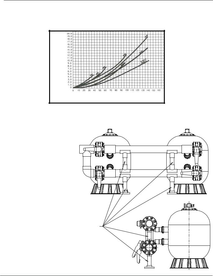
Pressure Drop Curve for the Triton Series Sand Filters
Pressure Drop in Feet
Flow Rate in G.P.M.
Installing Multiple Filters with Tandem Filter Piping Kits
CAUTION: WHEN MULITPLE FILTERS ARE
INSTALLED, WE HIGHLY RECOMMEND
THE USE OF A PENTAIR TANDEM FILTER
PIPING KIT. THESE KITS INCLUDE
PLUMBING SUPPORTS (BETWEEN
INLET AND OUTLET PIPING AND
BETWEEN OUTLET PIPING AND
FLOOR) TO ASSURE INTEGRITY
OF THE INSTALLATION.
SEE FIGURE A.
FIGURE A.
INLET
OUTLET
CAUTION: PENTAIR RECOMMENDS THE USE OF A TANDEM FILTER PLUMBING KIT(S) OR SOME SORT OF PLUMBING SUPPORT
TO ASSURE PLUMBING INTEGRITY. FAILURE TO INCLUDE THESE SUPPORTS COULD VOID YOUR WARRANTY.
Triton® Fiberglass Sand Filter Installation and User’s Guide

|
|
|
13 |
TRITON II |
& TRITON HD FIBERGLASS SAND FILTER |
|
|
|
|
|
TR40 |
Replacement Parts |
|
|
|
|
|
|
TR50 |
|
33 |
|
TR60 |
|
|
|
|
1 |
|
|
TR60 ClearPro |
|
|
|
|
2 |
|
|
TR100 |
34 |
|
TR100HD |
|
|
|
||
|
|
|
|
3 |
|
|
TR140 |
4 |
|
19 |
|
|
|
|
|
5 |
|
|
DETAIL A |
6 |
|
|
After Dec. 1, 1991 |
|
|
6" BUTTRESS THREAD |
|
7 |
|
|
|
27 |
|
|
|
|
|
|
|
35 |
|
|
|
8 |
|
|
|
9 |
|
|
|
10 |
|
|
DETAIL B |
|
|
|
|
|
|
|
Before Dec. 1, 1991 |
11 |
20 |
|
6" "V" THREAD |
|
|
|
|
12 |
21 |
22 |
|
|
|
||
|
23 |
|
|
13 |
|
|
|
|
25 |
|
|
|
|
24 |
|
14 |
|
29 |
|
15
16
17
26
18
32
29
30, 31
28
Filters manufactured after Dec 1, 1991 utilize a 6 in. buttress thread in the filter tank top opening and on the closure, see Detail A.
Filters manufactured before Dec 1, 1991 utilize a 6 in. “V” type thread, see Detail B.
6 in. closures in Detail A. and B. are NOT interchangeable.
26
|
17 |
Used on |
18 |
|
|
|
TR100 and |
|
|
|
|
|
|
TR140 filters. |
|
|
|
|
|
|
|
|
|
|
|
|
|
|
|
|
|
|
|
|
|
|
|
|
|
|
|
|
|
|
|
|
|
|
|
|
|
|
|
|
|
|
|
|
|
|
|
|
|
|
|
|
|
|
|
|
|
|
|
MODEL |
A DIM. |
B DIM. |
C DIM. |
D DIM. |
|
|
|
|
|
|
|
|
|
|
|
|
|
|
|
|
|
|
|
|
|
|
|
|
|
|
|
|||||
|
|
|
|
|
|
|
|
|
|
|
|
|
|
|
|
|
|
|
|
|
|
|
|
|
|
|
|
|
|
|
|
|
|
|
|
|
|
|
|
|
|
|
|
|
|
|
|
|
|
|
|
|
|
|
|
|
|
|
TR40 |
30 ½ in. |
19½ in. |
10 ¾ in. |
32 ½ in. |
|
|
|
|
|
|
|
|
|
|
|
|
|
|
|
|
|
|
|
|
|
|
|
|
|
|
|
|||||
|
|
|
|
|
|
|
|
|
|
|
|
|
|
|
|
|
|
|
|
|
|
|
|
|
|
|
|||||
|
|
|
|
|
|
|
|
|
|
|
|
|
|
|
|
|
|
|
|
|
|
|
|
|
|
|
|
|
|
|
|
|
|
|
|
|
|
|
|
|
|
|
|
|
|
|
|
|
|
|
|
|
|
|
|
|
|
|
TR50 |
34 ¾ in. |
21½ in. |
11-7/8 in. |
36 ¾ in. |
|
|
|
|
|
|
|
|
|
|
|
|
|
|
|
|
|
|
|
|
|
|
|
|
|
|
|
|||||
|
|
|
|
|
|
|
|
|
|
|
|
|
|
|
|
|
|
|
|
|
|
|
|
|
|
|
|
|
|
|
|
|
|
|
|
|
|
|
|
|
|
|
|
|
|
|
|
|
|
|
|
|
|
|
|
|
|
|
TR60 |
35 ½ in. |
24½ in. |
13-5/8 in. |
37 ½ in. |
|
|
|
|
|
|
|
|
|
|
|
|
|
|
|
|
|
|
|
|
|
|
|
|
|
|
|
|||||
|
|
|
|
|
|
|
|
|
|
|
|
|
|
|
|
|
|
|
|
|
|
|
|
|
|
|
|
|
|
|
|
|
|
|
|
|
|
|
|
|
|
|
|
|
|
|
|
|
|
|
|
|
|
|
|
|
|
|
TR60 ClearPro |
35 ½ in. |
24½ in. |
13-5/8 in. |
37 ½ in. |
|
|
|
|
|
|
|
|
|
|
|
|
|
|
|
|
|
|
|
|
|
|
|
|
|
|
|
|||||
|
|
|
|
|
|
|
|
|
|
|
|
|
|
|
|
|
|
|
|
|
|
|
|
|
|
|
|||||
|
|
|
|
|
|
|
|
|
|
|
|
|
|
|
|
|
|
|
|
|
|
|
|
|
|
|
|
|
|
|
|
|
|
|
|
|
|
|
|
|
|
|
|
|
|
|
|
|
|
|
|
|
|
|
|
|
|
|
TR100 |
39 ¾ in. |
30½ in. |
16 ¼ in. |
41 ¾ in. |
|
|
|
|
|
|
|
|
|
|
|
|
|
|
|
|
|
|
|
|
|
|
|
|||||||||
|
|
|
|
|
|
|
|
|
|
|
|
|
|
|
|
|
|
|
|
|
|
|
|
|
|
|
|
|
|
|
|
|
|
|
|
|
|
|
|
|
|
|
|
|
|
|
|
|
|
|
|
|
|
|
|
|
|
|
TR100HD |
39 ¾ in. |
30½ in. |
16 ¼ in. |
41 ¾ in. |
|
|
|
|
|
|
|
|
|
|
|
|
|
|
|
|
|
|
|
|
|
|
|
|
|
|
|
|||||
|
|
|
|
|
|
|
|
|
|
|
|
|
|
|
|
|
|
|
|
|
|
|
|
|
|
|
|
|
|
|
|
|
|
|
|
|
|
|
|
|
|
|
|
|
|
|
|
|
|
|
|
|
|
|
|
|
|
|
TR140 |
45 ¼ in. |
36½ in. |
18 ¾ in. |
47 ¼ in. |
|
|
|
|
|
|
|
|
|
|
|
|
|
|
|
|
|
|
|
|
|
|
|
|
|
|
|
|||||
|
|
|
|
|
|
|
|
|
|
|
|
|
|
|
|
|
|
|
|
|
|
|
|
|
|
|
|||||
|
|
|
|
|
|
|
|
|
|
|
|
|
|
|
|
|
|
|
|
|
|
|
|
|
|
|
|
|
|
|
|
|
|
|
|
|
|
|
|
|
|
|
|
|
|
|
|
|
|
|
|
|
|
|
|
|
|
|
|
|
|
|
|
Triton® Fiberglass Sand Filter Installation and User’s Guide
14
Item |
|
TRITON II & TRITON HD SAND FILTERS |
|
Part No. |
|
No. |
|
Description |
|
|
|
1 |
154689 |
Air bleeder/tee assy. |
|
|
|
2 |
154700 |
Adapter - brass air bleeder |
|
|
|
3 |
155050 |
Gauge - back mount pressure |
|
|
|
4 |
154661 |
O-ring - air bleeder adapter |
|
|
|
5 |
154664 |
Nut - 3/8 in. - 16 s/s |
|
|
|
6 |
154570 |
Closure - 6 in. buttress thread, see Detail A |
|
|
|
6 |
154559 |
Closure - 6 in. "V" thread Blk., see Detail B |
|
|
|
7 |
154493 |
O-ring closure, white |
|
|
|
8 |
150035 |
Strainer ECL/TR |
|
|
|
9 |
150039 |
Tube air relief TR40 |
|
|
|
9 |
150040 |
Tube air relief TR50/60 |
|
|
|
9 |
150041 |
Tube air relief TR100 |
|
|
|
9 |
150042 |
Tube air relief TR140 |
|
|
|
10 |
154598 |
Diffuser assy. TR40/50 |
|
|
|
10 |
154599 |
Diffuser assy. TR60 |
|
|
|
10 |
154462 |
Diffuser assy. TR100 |
|
|
|
10 |
154906 |
Diffuser assy. TR140 |
|
|
|
11 |
154803 |
Piping assy. upper TR40 |
|
|
|
11 |
156814 |
Piping assy. upper TR50 |
|
|
|
11 |
154533 |
Piping assy. upper TR60 |
|
|
|
11 |
154426 |
Piping assy. upper TR100 |
|
|
|
11 |
154500 |
Piping assy. upper TR140 |
|
|
|
12 |
150036 |
Connector air relief tube |
|
|
|
13 |
154801 |
Piping assy. lower TR40 |
|
|
|
13 |
156816 |
Piping assy. lower TR50 |
|
|
|
13 |
154805 |
Piping assy. lower TR60 |
|
|
|
13 |
155284 |
Piping assy. lower TR60 ClearPro -1/4 Turn Lateral |
|
|
|
13 |
154807 |
Piping assy. lower TR100 |
|
|
|
13 |
154489 |
Piping assy. lower TR140 |
|
|
|
14 |
154636 |
Tank & ft. assy. TR40 - 6 in. btr. thd., Detail A |
|
|
|
14 |
154637 |
Tank & ft. assy. TR50 - 6 in. btr. thd., Detail A |
|
|
|
14 |
154638 |
Tank & ft. assy. TR60 - 6 in. btr. thd., Detail A |
|
|
|
14 |
154639 |
Tank & ft. assy. TR100 - 6 in. btr. thd., Detail A |
|
|
|
14 |
154640 |
Tank & ft. assy. TR140 - 6 in. btr. thd., Detail A |
|
|
|
14 |
156224 |
Tank & ft. assy. TR100HD - btr. thd. Blk. HD |
|
|
|
TRITON II & TRITON HD
FIBERGLASS SAND FILTER
Replacement Parts
TR40
TR50
TR60 TR60 ClearPro TR100 TR100HD TR140
NOTES
Filters manufactured after Dec 1, 1991 utilize a 6 in. buttress thread in the filter tank top opening and on the closure, see Detail A.
Filters manufactured before Dec 1, 1991 utilize a 6 in. “V” type thread, see Detail B.
6 in. closures in Detail A. and B. are NOT interchangeable.
To determine manufacture date, the first 4 digits of the serial number indicate the month and year product was manufactured.
TR60 ClearPro - 1/4 Turn Lateral for filters manufactured after May 15, 2007 utilize Lower Piping Assy. P/N 155284.
13
 15
15
16
DETAILED VIEW
Detail for Triton® II - TR60 Filters with ClearPro Technology™
Triton® Fiberglass Sand Filter Installation and User’s Guide
Item |
|
TRITON II & TRITON HD SAND FILTERS |
|
Part No. |
|
No. |
|
Description |
|
|
|
15 |
152290 |
Lateral - 6 11/16 in. L TR40/50/60, 8 req. |
|
|
|
15 |
150085 |
Lateral Assy. - 1/4 turn TR60, 6 req. |
|
|
|
15 |
150088 |
Lateral Assy. - TR60 ClearPro, 6 req. |
|
|
|
15 |
152202 |
Lateral - 9 1/8 in. L TR100, 8 req. |
|
|
|
15 |
154543 |
Lateral - 6½ in. L TR100, 8 req. |
|
|
|
15 |
154540 |
Lateral - 12 in. L TR140, 8 req. |
|
|
|
16 |
154763 |
Hub Lateral TR40/50/60 |
|
|
|
16 |
152222 |
Hub Assy. TR60 ClearPro |
|
|
|
16 |
154453 |
Hub Lateral TR100/140 |
|
|
|
17 |
152220 |
Sand drain 2 in. |
|
|
|
17 |
154698 |
Spigot ¾ in. NPT sand drain |
|
|
|
17 |
154685 |
Spigot ½ in. NPT sand drain |
|
|
|
18 |
154871 |
Cap thd. 1½ in. |
|
|
|
18 |
357161 |
Plug ¼ in. NPT drain |
|
|
|
19 |
154512 |
Wrench 6 in. closure |
|
|
|
19 |
154510 |
Wrench closure aluminum |
|
|
|
19 |
151608 |
Wrench 8½ in. closure aluminum |
|
|
|
20 |
154412 |
Locknut 2 in. internal, 2 req. |
|
|
|
21 |
154416 |
Spacer 2 in. internal, 2 req. |
|
|
|
22 |
154492 |
O-ring 2 in. bulkhead, 2 req. |
|
|
|
23 |
154408 |
Spacer 2 in. external, 2 req. |
|
|
|
24 |
154538 |
Gasket 2 in. bulkhead, 2 req. |
|
|
|
25 |
154405 |
Bulkhead 2 in., 2 req. |
|
|
|
26 |
274494 |
O-ring 3/16 in. X 2 5/8 in. i.d. |
|
|
|
26 |
192115 |
O-ring #2-12 air adapter |
|
|
|
27 |
154418 |
Washer 3/8 in. s/s |
|
|
|
28 |
154926 |
Foot 16 in. dia., TR40/50 (see NOTE 1) |
|
|
|
28 |
154520 |
Foot 19 in. dia., TR60 (see NOTE 1) |
|
|
|
28 |
154596 |
Foot 24 in. dia., TR100/140 (see NOTE 1) |
|
|
|
29 |
274494 |
O-ring valve adptr., 2 req. |
|
|
|
30 |
271092 |
2 in. thd. adptr. kit |
|
|
|
31 |
271094 |
1½ in. thd. adptr. kit |
|
|
|
32 |
271096 |
1½ in. & 2 in. slip adptr. kit |
|
|
|
33 |
154641 |
Kit closure, 6 in. buttress thd., Blk., DETAIL A |
|
|
|
33 |
154697 |
Kit closure, 6 in. "V" thd., Tan, DETAIL B |
|
|
|
33 |
154856 |
Kit closure, 8½ in. buttress thd., Blk. |
|
|
|
34 |
154687 |
Fitting package complete (see NOTE 2) |
|
|
|
35 |
154611 |
Spacer air vent strainer 3¾ in. TR40 |
|
|
|
35 |
154612 |
Spacer air vent strainer 4½ in. TR50/60 |
|
|
|
35 |
154613 |
Spacer air vent strainer 5½ in. TR100 |
|
|
|
35 |
154614 |
Spacer air vent strainer 5 in. TR140 |
|
|
|
|
154402 |
Tape ft. mounting TR40/50/60, 3 req. |
|
|
|
|
154407 |
Tape ft. mounting TR100/140, 3 req. |
|
|
|
|
151602 |
Bulkhead wrench 2 in. |
|
|
|
|
154714 |
Bulkhead kit, include items 20-25 |
|
|
|
15
TRITON II & TRITON HD
FIBERGLASS SAND FILTER
Replacement Parts
TR40
TR50
TR60 TR60 ClearPro TR100 TR100HD TR140
NOTES
Filters manufactured after Dec 1, 1991 utilize a 6 in. buttress thread in the filter tank top opening and on the closure, see Detail A.
Filters manufactured before Dec 1, 1991 utilize a 6 in. “V” type thread, see Detail B.
6 in. closures in Detail A. and B. are NOT interchangeable.
To determine manufacture date, the first 4 digits of the serial number indicate the month and year product was manufactured.
Used on Filters manufactured before 5-85.
Used on Filters manufactured after 5-85.
Used on Filters manufactured before 3-83.
Used on Filters manufactured after 3-83 thru 3-96.
For Installations w/out Valve (Pair).
Used on TR100 & 140 Filters.
NOTE 1: Replacement of tank foot requires the use of foot mounting tape. See P/N’s.
NOTE 2: Fitting package includes items 1, 2, 4, 5 and 27.
Triton® Fiberglass Sand Filter Installation and User’s Guide
16
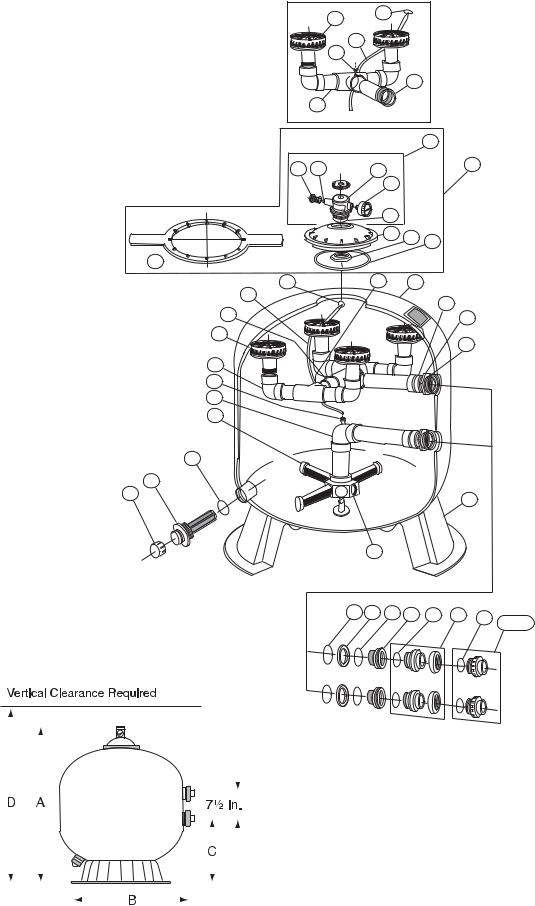
TRITON 100C & 140C FIBERGLASS SAND FILTER
Replacement Parts
|
|
9 |
32 |
|
|
|
|
|
|
|
|
|
|
30 |
31 |
|
|
|
|
|
|
|
|
|
|
|
|
11 |
|
|
10 |
|
|
|
|
TR 100C |
|
|
|
|
3 |
TR 140C |
2 |
|
6 |
|
37 |
1 |
|
|
|
||
|
|
|
4 |
|
|
|
|
|
5 |
|
|
|
|
|
7 |
13 |
8 |
|
|
|
|
|
27
32 |
30 |
14 |
31 |
|
11 |
12 |
|
|
|
18 |
|
9 |
|
19 |
|
|
10
29
28
17
24
26 |
25 |
|
16 |
||
|
15
20 21 |
22 |
23 |
33 |
34 |
20 |
35, 36 |
UPPER PIPING SHOWN |
|
|
|
|
||
|
|
|
|
|
|
|
IN ISOMETRIC |
|
|
|
|
|
|
TANK VIEW TR 140C |
|
|
|
|
|
|
TR100C
TR140C
|
|
|
|
|
|
|
|
|
|
|
|
|
|
|
|
|
|
|
|
|
|
|
|
|
|
|
|
|
|
|
|
|
|
|
|
|
|
|
|
|
|
|
|
|
|
|
|
|
|
|
|
|
|
|
|
|
|
|
|
|
|
|
|
|
|
|
|
|
|
|
|
|
|
|
|
|
|
|
|
|
|
|
|
|
|
|
|
|
|
|
|
|
|
|
|
|
|
|
|
|
|
|
|
|
|
|
|
|
|
|
|
|
|
|
|
|
|
|
|
|
|
MODEL |
A DIM. |
B DIM. |
C DIM. |
D DIM. |
|
|
|
|
|
|
|
|
|
|
|
|
|
|
|
|
|
|
|
|
|
|
|
|
|
|
|
|
|
|
|
|
|
|
|
|
|
|
|
|
|
|
|
|
|
|
|
|
|
|
|
|
|
|
|
|
|
|
|
TR100C |
39¾ in. |
30½ in. |
16½ in. |
43¾ in. |
|
|
|
|
|
|
|
|
|
|
|
|
|
|
|
|
|
|
|
|
|
|
|
|
|
|
|
|
|||||
|
|
|
|
|
|
|
|
|
|
|
|
|
|
|
|
|
|
|
|
|
|
|
|
|
|
|
|
|
|
|
|
|
|
|
|
|
|
|
|
|
|
|
|
|
|
|
|
|
|
|
|
|
|
|
|
|
|
|
|
|
|
|
|
|
|
|
|
|
|
|
|
|
|
|
|
|
|
|
|
|
|
|
|
|
|
|
|
|
|
TR140C |
45¼ in. |
36½ in. |
18¾ in. |
49¼ in. |
|
|
|
|
|
|
|
|
|
|
|
|
|
|
|
|
|
|
|
|
|
|
|
|
|
|
|
|
|||||
|
|
|
|
|
|
|
|
|
|
|
|
|
|
|
|
|
|
|
|
|
|
|
|
|
|
|
|
|
|
|
|
|
|
|
|
|
|
|
|
|
|
|
|
|
|
|
|
|
|
|
|
|
|
|
|
|
|
|
|
|
|
|
|
|
|
|
|
|
|
|
|
|
|
|
|
|
|
|
|
|
|
|
|
|
|
|
|
|
|
|
|
|
|
|
|
|
|
|
|
|
|
|
|
|
|
|
|
|
|
|
|
|
|
|
|
|
|
|
|
|
|
|
|
|
|
|
|
|
|
|
|
|
|
|
|
|
|
|
|
|
|
|
|
|
|
|
|
|
|
|
|
|
|
|
|
|
|
|
|
|
|
|
|
|
|
|
|
|
|
|
|
|
|
|
|
|
|
|
|
|
|
|
|
|
|
|
|
|
|
|
|
|
|
|
|
|
|
|
|
|
|
|
|
|
|
|
|
|
|
|
|
|
|
|
|
|
|
|
|
|
|
|
|
|
|
|
|
|
|
|
|
|
|
|
|
|
|
|
|
|
|
|
|
|
|
|
|
|
|
|
|
|
|
|
|
Triton® Fiberglass Sand Filter Installation and User’s Guide

Item |
|
TR100C & TR140C SAND FILTERS |
No. |
Part No. |
Description |
|
|
|
1 |
273512 |
Air bleeder w/ o-ring |
|
|
|
2 |
273513 |
O-ring air bleeder screw |
|
|
|
3 |
273564 |
Manual air relief body assy. |
|
|
|
4 |
155050 |
Pressure gauge |
|
|
|
5 |
274494 |
O-ring 3/16 in. X 2-5/8 in. i.d.. |
|
|
|
6 |
273564 |
Valve body machined |
|
|
|
7 |
154575 |
Closure 8½ in. buttress |
|
|
|
8 |
152509 |
Square ring 8½ in. |
|
|
|
9 |
154599 |
Diffuser TR100C |
|
|
|
9 |
154599 |
Diffuser TR140C |
|
|
|
10 |
156355 |
Piping assy. upper TR100C, TR140C |
|
|
|
11 |
156344 |
Piping assy. upper inlet TR100C, TR140C |
|
|
|
12 |
156354 |
Piping connecting assy. upper TR140C |
|
|
|
13 |
154412 |
Nut 2 in. internal |
|
|
|
14 |
153430 |
Tank & ft. assy. TR100C - 8½ in. btr. THD. - Blk |
|
|
|
14 |
153431 |
Tank & ft. assy. TR140C - 8½ in. btr. THD. - Blk |
|
|
|
15 |
154453 |
Hub lateral TR100C/TR140C |
|
|
|
16 |
154596 |
Foot 24 in. dia. TR100C/TR140C |
|
|
|
17 |
152202 |
Lateral 9 1/8 in. TR100C, 8 req. |
|
|
|
17 |
154540 |
Lateral 12 in. TR140C, 8 req. |
|
|
|
18 |
154412 |
Locknut 2 in. internal |
|
|
|
19 |
154416 |
Spacer 2 in. internal |
|
|
|
20 |
154492 |
O-ring 2 in. bulkhead |
|
|
|
21 |
154408 |
Spacer 2 in. external |
|
|
|
22 |
154538 |
Gasket 2 in. bulkhead |
|
|
|
23 |
154405 |
Bulkhead 2 in. |
|
|
|
24 |
274494 |
O-ring 3/16 in. X 2 5/8 in. i.d. |
|
|
|
|
154407 |
Tape ft. mounting |
|
|
|
25 |
152220 |
2 in. sand drain |
|
|
|
26 |
154871 |
Cap thd. 1½ in. |
|
|
|
27 |
154527 |
Wrench 8½ in. closure |
|
|
|
27 |
151608 |
Wrench 8½ in. aluminum |
|
|
|
28 |
154807 |
Piping assy. lower TR100C |
|
|
|
28 |
154489 |
Piping assy. lower TR140C |
|
|
|
29 |
150036 |
Connector air relief tube |
|
|
|
30 |
273071 |
Screw #14 18-8 TR100C |
|
|
|
31 |
150041 |
Tube air relief TR100C |
|
|
|
31 |
150042 |
Tube air relief TR140C |
|
|
|
17
TRITON 100C & 140C FIBERGLASS SAND FILTER
Replacement Parts
TR100C
TR140C
Item |
|
TR100C & TR140C SAND FILTERS |
No. |
Part No. |
Description |
|
|
|
32 |
150035 |
Strainer air relief |
|
|
|
33 |
274494 |
O-ring valve adptr. |
|
|
|
|
|
1½ in. & 2 in. slip adptr. kit for inst. w/o valve |
34 |
271096 |
(pair) |
|
|
|
35 |
271092 |
2 in. thd. adptr. kit for inst. w/o valve (pair) |
|
|
|
36 |
271094 |
1½ in. thd. adptr. kit for inst. w/o valve (pair) |
|
|
|
37 |
154856 |
Kit closure 8½ in. btr. THD. - Blk. |
|
|
|
NOTES
Different quantities required for TR100C and TR140C Filters.
Triton® Fiberglass Sand Filter Installation and User’s Guide
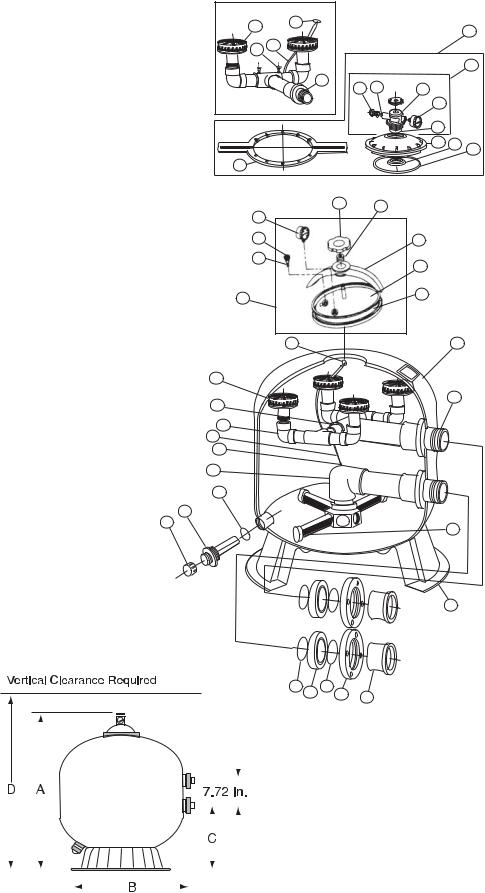
18
TRITON 100C-3 & 140C-3 FIBERGLASS SAND FILTER
Replacement Parts
TR 100C-3 Upper Piping |
|
|
|
|
|
29 |
30 |
|
|
|
11 |
|
|
|
|
||
|
|
|
|
|
|
28 |
26 |
|
|
|
|
|
|
|
|
|
6 |
|
13 |
2 |
3 |
|
|
|
1 |
|
|
||
|
|
|
4 |
|
|
|
|
|
5 |
|
|
|
|
|
7 |
8 |
9 |
|
|
|
|
|
|
10 |
|
|
|
|
|
31 |
32 |
33 |
|
|
|
|
|
|
|
|
|
1 |
|
|
34 |
|
|
2 |
|
|
35 |
|
|
|
|
|
|
|
|
36 |
|
|
9 |
|
|
|
|
|
|
|
|
|
30 |
|
|
12 |
|
29 |
|
|
|
|
|
28 |
|
|
|
13 |
|
|
|
|
|
|
|
27 |
|
|
|
|
|
26 |
|
|
|
|
|
25 |
|
|
|
|
|
19 |
|
|
|
|
|
24 |
|
|
|
|
|
23 |
|
|
|
|
|
22 |
|
|
|
21 |
|
|
|
|
|
|
|
20
14 15 |
16 17 |
18 |
|
|
TR100C-3 TR140C-3
|
|
|
|
|
|
|
|
|
|
|
|
|
|
|
|
|
|
|
|
|
|
|
|
|
|
|
|
|
|
|
|
|
|
|
|
|
|
|
|
|
|
|
|
|
|
|
|
|
|
|
|
|
|
MODEL |
A DIM. |
B DIM. |
C DIM. |
D DIM. |
|
|
|
|
|
|
|
|
|
|
|
|
|
|
|
|
|
|
|
|
|
|
|
|
|
|
|||||
|
|
|
|
|
|
|
|
|
|
|
|
|
|
|
|
|
|
|
|
|
|
|
|
|
|
|
|
|
|
|
|
|
|
|
|
|
|
|
|
|
|
|
|
|
|
|
|
|
|
|
|
|
|
|
|
|
|
|
|
|
|
|
|
|
|
|
|
|
|
|
|
|
|
|
|
|
|
|
|
|
|
|
|
TR100C-3 |
39¾ in. |
30½ in. |
16-1/16 in. |
43¾ in. |
|
|
|
|
|
|
|
|
|
|
|
|
|
|
|
|
|
|
|
|
|
|
|
|
|
|
|||||
|
|
|
|
|
|
|
|
|
|
|
|
|
|
|
|
|
|
|
|
|
|
|
|
|
|
|
|
|
|
|
|
|
|
|
|
|
|
|
|
|
|
|
|
|
|
|
|
|
|
|
|
|
|
TR140C-3 |
45¼ in. |
36½ in. |
18½ in. |
49¼ in. |
|
|
|
|
|
|
|
|
|
|
|
|
|
|
|
|
|
|
|
|
|
|
|||||||||
|
|
|
|
|
|
|
|
|
|
|
|
|
|
|
|
|
|
|
|
|
|
|
|
|
|
|
|
|
|
|
|
|
|
|
|
|
|
|
|
|
|
|
|
|
|
|
|
|
|
|
|
|
|
|
|
|
|
|
|
|
|
|
|
|
|
|
|
|
|
|
|
|
|
|
|
|
|
|
|
|
|
|
|
|
|
|
|
|
|
|
|
|
|
|
|
|
|
|
|
|
|
|
|
|
|
|
|
|
|
|
|
|
|
|
|
|
|
|
|
|
|
|
|
|
|
|
|
|
|
|
|
|
|
|
|
|
|
|
|
|
|
|
|
|
|
|
|
|
|
|
|
|
|
|
|
|
|
|
|
|
|
|
|
|
|
|
|
|
|
|
|
|
|
|
|
|
|
|
|
|
|
|
|
|
|
|
|
|
|
|
|
|
|
|
|
|
|
|
|
|
|
|
|
|
|
|
|
|
|
|
|
|
|
|
|
|
|
|
|
|
|
|
|
|
|
|
|
|
|
|
|
|
|
|
|
|
|
|
|
Triton® Fiberglass Sand Filter Installation and User’s Guide

Item |
Part No. |
TRITON 100C-3 &140C-3 SAND FILTERS |
No. |
|
Description |
|
|
|
1 |
273512 |
Air bleed with o-ring |
|
|
|
2 |
273513 |
O-ring air bleeder screw |
|
|
|
3 |
273564 |
Valve body machined |
|
|
|
4 |
155050 |
Pressure gauge |
|
|
|
5 |
154494 |
O-ring adapter, 6 in. |
|
|
|
6 |
273564 |
Manual air relief assy. |
|
|
|
7 |
154575 |
Closure 8½ in. |
|
|
|
8 |
154412 |
Nut 2 in. internal |
|
|
|
9 |
152509 |
Square ring closure |
|
|
|
10 |
154527 |
Wrench 8½ in. closure |
|
|
|
11 |
154856 |
Kit 8½ in. closure buttress thd. |
|
|
|
12 |
153430 |
Tank & ft. assy. TR100C-3 - buttress |
|
|
|
12 |
153431 |
Tank & ft. assy. TR140C-3 - buttress |
|
|
|
13 |
154007 |
Upper piping assy. TR100C-3 |
|
|
|
13 |
154008 |
Upper piping assy. TR140C-3 |
|
|
|
14 |
154005 |
O-ring Parker 2-343, 2 req. |
|
|
|
15 |
154002 |
Spacer 3 in., 2 req. |
|
|
|
16 |
154004 |
O-ring Parker 2-342, 2 req. |
|
|
|
17 |
154003 |
Flange 3 in., 2 req. |
|
|
|
18 |
154001 |
Adapter flange 3 in., 2 req. |
|
|
|
19 |
154009 |
Lower piping assy. TR100C-3 |
|
|
|
19 |
154010 |
Lower piping assy. TR140C-3 |
|
|
|
20 |
154596 |
Foot 24 dia. TR100C-3/140C-3 |
|
|
|
21 |
152202 |
Lateral 9 in. TR100C-3, 8 req. |
|
|
|
21 |
154540 |
Lateral 12 in. TR140C-3, 8 req. |
|
|
|
22 |
154871 |
Cap thd. 1½ in. |
|
|
|
23 |
152220 |
Sand drain 2 in. |
|
|
|
24 |
274494 |
O-ring 3/16 in. X 2 5/8 in. i.d., 2 req. |
|
|
|
25 |
154441 |
Connector air relief tube |
|
|
|
26 |
150041 |
Tube air relief TR100C-3 (23 in.) |
|
|
|
26 |
150042 |
Tube air relief TR140C-3 (27 in.) |
|
|
|
27 |
154018 |
Diffuser piping assy. TR140C-3, 2 req. |
|
|
|
28 |
552474 |
Screw - #10-1½ in. flathead phillips, 2 req. |
|
|
|
29 |
154599 |
Diffuser - 2 req'd. for TR100C-3 |
|
|
|
29 |
154599 |
Diffuser - 4 req'd. for TR140C-3 |
|
|
|
19
TRITON 100C-3 & 140C-3 FIBERGLASS SAND FILTER
Replacement Parts
|
|
|
TR100C-3 |
|
|
|
|
TR140C-3 |
|
|
|
|
||
Item |
Part No. |
TRITON 100C-3 &140C-3 SAND FILTERS |
||
No. |
|
|
Description |
|
|
|
|
||
30 |
150035 |
Strainer ELC/TR |
||
|
|
|
||
31 |
190058 |
Pressure Gauge, ¼ in. psi |
||
|
|
|
||
32 |
154581 |
Knob TR oval |
||
|
|
|
||
33 |
154582 |
Spring TR oval |
||
|
|
|
||
34 |
154579 |
Bridge TR oval |
||
|
|
|
||
35 |
154576 |
Closure-oval |
||
|
|
|
||
36 |
156841 |
Kit TR oval closure |
||
|
|
|
|
|
|
|
|
|
|
|
|
|
NOTES |
|
|
|
P/N 156841 includes items: 1, 9, 31 thru 35. |
|
|
|
|
Used on filters manufactured before 3-97. |
|
|
|
|
Used on filters manufactured after 3-97. |
|
|
|
|
|
|
|
Triton® Fiberglass Sand Filter Installation and User’s Guide

20
NOTES
SAVE THESE INSTRUCTIONS
Triton® Fiberglass Sand Filter Installation and User’s Guide
 Loading...