


Slide Backwash Valve
H0569400B
Jandy
®
Slide
Backwash Valve
Installation and
Op er a tion Man u al
FOR YOUR SAFETY - This product must be installed and serviced by authorized personnel
qual i fi ed in pool/spa installation and maintenance. Improper installation and/or operation
will void the warranty.
Installation and Operation Data

Page 3
Section 1. SVLV8 Installation
1. Remove the Slide Valve from the packaging. Twist
the handle on the Slide Valve several times to
verify that the piston moves freely.
FOR YOUR SAFETY: This product must be installed and serviced by authorized personnel qual i fi ed
in pool/spa installation and maintenance. Improper installation and/or operation will void the warranty.
WARNING
Ensure that all electrical power to the system is turned off before approaching, inspecting or
troubleshooting any leaking valves that may have caused other electrical devices in the surrounding
area to get wet.
This document gives instructions for installing the
Jandy Slide Valve. The instructions must be followed
exactly. Read through the instructions completely before
starting the procedure. Please save these instructions.
The Jandy Slide Valve is designed to be used on either
sand or diatomaceous earth (DE) filters with a center to
center dimension of eight (8") inches (center of the inlet
port to the center of the outlet port). Combined with the
Jandy Versa-Coupler, the Slide Valve can be used on
filters with center to center dimensions of seven (7") to
nine (9") inches.
For Jandy Filters, Slide Valve p/n SVLV8 (with unions)
is ready to mount to DEL48 or DEL60 model filters
(in which the top port is the filter outlet). If mounting a
Jandy Slide Valve on Pentair or Sta-Rite Filters, use a
combination of p/n SVLV2 (Slide Valve without unions)
and p/n 8044 (Versa-Coupler Kit).
The Slide Valve is a two position valve. The valve
handle must be fully extended or fully depressed. This
valve can not be throttled. To operate the Slide Valve
on a DE filter in normal filtration mode, fully depress
the handle. To operate the Slide Valve on a sand filter
in normal filtration mode, fully extend the valve handle
(see Figure 1).
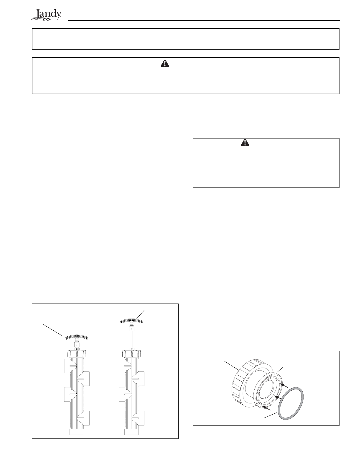
Figure 2. O-ring Placement
Coupling Nut
O-ring
Union Tail Piece
WARNING
Ensure that all electrical power to the system
is turned off before approaching, inspecting or
troubleshooting any leaking valves that may have
caused other electrical devices in the surrounding
area to get wet.
2. Turn off all power to the system. For retrofi t
installations only, follow steps "a" through "d".
For new installations skip steps "a" through "d"
and proceed to step 3.
a. Open the pressure relief valve on top of the
fi lter. Wait for all air to evacuate the system.
b. If the fi lter is below pool level, close the
suction and return line valves to isolate the
fi ltration system.
c. Remove the drain plug from the fi lter. Let the
water drain from the fi lter.
d. Remove the existing valve from the fi lter.
3. Remove the o-rings (2 total) from the packaging.
4. Place the o-rings on the face of the union tail
pieces, where the face of the Slide Valve union
will connect to the fi lter bulkheads (see Figure 2).
Make sure each O-ring is properly seated into the
groove of each union tail piece.
Figure 1. Handle Positions - Filter/Circulation
Mode(SVLV2 shown)
DE Filter
Handle fully depressed
(pushed down)
Sand Filter
Handle fully
extended
(pulled up)
Page 4
CAUTION
To avoid costly equipment damage, after verifying
proper water flow and prior to putting system into
normal operating conditions, flush the system using
Backwash mode until the waste water is clean.
Refer to Section 4 for Backwash mode operation
instructions.
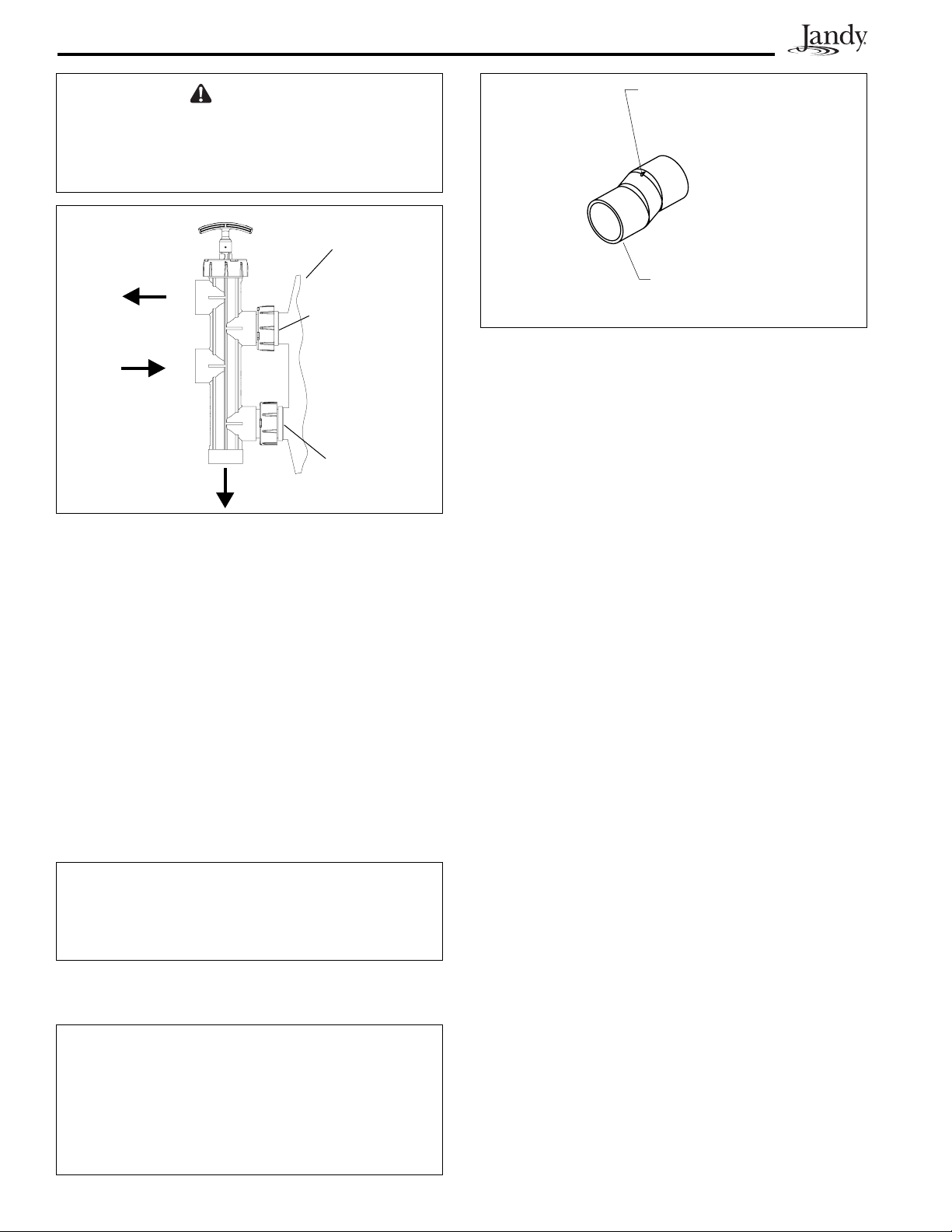
Figure 4. Jandy Versa-Coupler
Alignment
Mark
Versa-
Coupler
p/n 8044
CAUTION
Do not let any adhesive get inside the Slide Valve
body. Adhesive inside the valve body will prevent the
piston from moving freely, or cause the valve to leak.
To Pool
(PORT A)
To Waste (PORT E)
From
Pump
(PORT B)
Figure 3. SVLV8 Installed on Jandy DEL48 or
(DEL60)
5. Hold the Slide Valve upright and place onto the
fi lter bulkheads (see Figure 3).
6. Tighten both union nuts to secure the valve on the
fi lter.
7. Place fi lter and valve in proper location on the
equipment set pad.
8. Plumb the discharge of the pump into the Slide
Valve inlet labeled
PORT B
.
9. Plumb the Slide Valve outlet labeled
PORT A
to the
heater or pool return lines.
10. Plumb the Slide Valve outlet labeled
PORT E
to the
waste line as needed. Allow the connections to dry
for 24 hours.
NOTE: For new installations other than Jandy DEL48
or DEL60, use the SVLV2 and the Versa
Coupler Kit, p/n 8044 (See Figure 4).
If using the Slide Valve with a Pentair fi lter, use
Pentair Pool Products™ Union Set #27002, and
then proceed to section B. If using a Sta-rite
fi lter, use Sta-Rite
®
Union Set #PKGM188, then
proceed to section B.
Section 2. SVLV2 and Versa-Coupler
Installation
NOTE Certain fi lters may require only one (1) versa-
coupler (p/n 8044).
1. Slide one versa-coupler into
PORT C
and one into
PORT D
on the Slide Valve.
2. Hold the Slide Valve up to the fi lter and twist the
versa-couplers until they slide into the fi lter inlet
and outlet ports.
NOTE Make sure to align each versa-coupler to the
fi lter and the Slide Valve prior to gluing the
assembly. When the parts are in alignment,
mark each piece to ensure correct reassembly.
3. Remove the valve from the fi lter. Clean the versa-
couplers and glue them onto the valve using the
alignment marks as a reference.
4. Clean the versa-coupler and glue onto the fi lter.
Hold the coupler in place for a minimum of one
(1) minute.
5. Plumb the discharge of the pump into the Slide
Valve inlet labeled
PORT B
.
CAUTION
The Slide Valve has molded labels on each port (see
Figure 1). The ports on the SVLV8 are equipped with
union connections that match the connections on the
filter ports. Do not use pipe sealants on union nuts.
11. When the glue is dry, start the system and check
for proper water fl ow.
To Filter Body
(cut away view)
Filter Outlet
(PORT C)
Filter Inlet
(PORT D)
 Loading...