


1 1
MiniMax NT® LN Series
Pool & Spa Heaters
OPERATION & INSTALLATION MANUAL
To
Consumer
Retain For
Future
Reference
U.S. Patent Numbers 6,295,980 5,318,007 - 5,228,618 5,201,307 - 4,595,825
WARNING
FOR YOUR SAFETY - READ BEFORE OPERATING
•If you do not follow these instructions exactly, a fire or explosion may result, causing property damage, personal injury or loss of life.
•Improper installation, adjustment, alteration, service or maintenance can cause property damage, personal injury or death. Installation and service must be performed by a qualified installer, service agency or the gas supplier.
•Do not store or use gasoline or other flammable vapors and liquids in the vicinity of this heater or other appliances.
WHAT TO DO IF YOU SMELL GAS
•Do not try to light any appliance.
•Do not touch any electrical switch; do not use any phone in your building.
•Immediately call your gas supplier from a neighbor's phone. Follow the gas supplier's instructions.
•If you cannot reach your gas supplier, call the fire department.
For additional free copies of this manual; call (800) 831-7133.
Pentair Water Pool and Spa, Inc.
1620 Hawkins Ave., Sanford, NC 27330 • (919) 566-8000
10951 W. Los Angeles Ave., Moorpark, CA 93021 • (805) 523-2400
Rev. E 4-19-05 |
P/N 472089 |
2
Customer Service
If you have questions about ordering Pentair Water Pool and Spa replacement parts, and pool products, please use the following contact information.
Customer Service (8 A.M. to 5 P.M. Pacific Time)
Phone: (800) 831-7133 (press 3 in voice mail)
Fax: (800) 284-4151
Technical Support for Pentair Water Pool and Spa, Inc.
Sanford, North Carolina (8 A.M. to 5 P.M. Eastern Time)
Phone: (919) 566-8000
Fax: (919) 776-0562
Moorpark, California (8 A.M. to 5 P.M. Pacific Time)
Phone: (805) 523-2400 (Ext. 6502)
Fax: (805) 530-0194
Web site
visit www.pentairpool.com to find information about Pentair Water Pool and Spa, Inc.
© 2005 Pentair Water Pool and Spa, Inc.
1620 Hawkins Ave., Sanford, NC 27330 • (919) 556-8000
10951 West Los Angeles Ave., Moorpark, CA 93021 • (805) 523-2400
All rights reserved. Information in this document is subject to change without notice.
Trademarks and Disclaimers. MiniMax NT LN and the Pentair Pool Products logo are registered trademarks of Pentair
Water Pool and Spa, Inc. Other trademarks and trade names may be used in this document to refer to either the entities claiming the marks and names or their products. Pentair Water Pool and Spa, Inc. disclaims any proprietary interest in trademarks and trade names other than its own.
P/N 472089 |
Rev. E 4-19-05 |
|
3 |
Table of Contents |
|
Section I. Heater Identification Information ........................................................... |
4 |
Section II. Introduction ............................................................................................ |
5 |
Important Notices ...................................................................................................................................................................... |
5 |
Warranty Information ................................................................................................................................................................. |
5 |
Code Requirements ................................................................................................................................................................... |
6 |
Consumer Information and Safety ............................................................................................................................................. |
6 |
Section III. Installation .............................................................................................. |
7 |
Specifications ............................................................................................................................................................................ |
7 |
Plumbing Connections ............................................................................................................................................................... |
8 |
Valves ........................................................................................................................................................................................ |
8 |
Manual By-Pass ........................................................................................................................................................................ |
8 |
Below Pool Installation .............................................................................................................................................................. |
8 |
Water Connections .................................................................................................................................................................... |
9 - 10 |
Gas Connections ....................................................................................................................................................................... |
11 |
Sediment Traps ......................................................................................................................................................................... |
11 |
Gas Pipe Sizing ......................................................................................................................................................................... |
12 |
Testing Gas Pressure/Gas Pressure Requirements .................................................................................................................. |
13 |
Indoor Venting—General Requirements .................................................................................................................................... |
14 |
Indoor (USA) / Outdoor (Canada) Installations .......................................................................................................................... |
15 |
Combustion Air Supply .............................................................................................................................................................. |
16 |
Vent Adaptors ............................................................................................................................................................................ |
16 |
Indoor Installations —Venting Guidelines .................................................................................................................................. |
17 |
Outdoor Installations —Venting Guidelines ............................................................................................................................... |
18 |
Outdoor Vent Kit ........................................................................................................................................................................ |
18 |
Electrical Connections ............................................................................................................................................................... |
19 |
Wiring Diagram—NT LN with DDTC .......................................................................................................................................... |
20 |
Section IV. Operation ................................................................................................ |
21 |
Basic System Operation ............................................................................................................................................................ |
21 |
HSI (Hot-Surface Ignition) Lighting/Operation ........................................................................................................................... |
21 |
Safety Controls .......................................................................................................................................................................... |
22 - 23 |
Digital Display Temperature Controller (DDTC) ......................................................................................................................... |
24 - 27 |
Section V. Troubleshooting ....................................................................................... |
28 |
Troubleshooting (DDTC) ............................................................................................................................................................ |
28 |
Troubleshooting (General) ......................................................................................................................................................... |
29 |
Service Checks - Ignition Module .............................................................................................................................................. |
29 |
Section VI. Maintenance ......................................................................................................... |
30 |
Maintenance Instructions ........................................................................................................................................................... |
30 |
Pressure Relief Valve ................................................................................................................................................................ |
30 |
Energy Saving Tips .................................................................................................................................................................... |
30 |
Spring, Fall and Winter Operation ............................................................................................................................................. |
31 |
Chemical Balance ...................................................................................................................................................................... |
32 |
Replacement Parts — NT LNw/DDTC ....................................................................................................................................... |
33 - 34 |
Rev. E 4-19-05 |
P/N 472089 |
Section I.Heater Identification Information |
4 |
Heater Identification Information
To identify the heater, see rating plate on the inner front panel of the heater. There are two designators for each heater, one is the Model Number and the other is the Heater Identification Number (HIN).
a.Heater Identification Number (HIN)
The following example simplifies the identification system:
1)HTR : Heater
2)(200, 250, 300 or 400) : Input rating (Btu/hr) X 1000
3)NT : MiniMax NT Series
4)LN : Series Character
5)NH : Gas type (Natural gas) and ignition system (Hot Surface Ignition)
6)Options :
Blank: Standard Model
ASME: ASME Certified (Bronze Headers)
ASHI: ASME Certified Bronze Header and High Altitude Rating HALT: High Altitude Rating
HEATER IDENTIFICATION INFORMATION — (HIN)
H. I. N.
HEATER IDENTIFICATION NUMBER
ID DESIGNATOR FOR PENTAIR POOL & SPA HEATERS
|
|
HTR |
|
400 |
|
NT |
|
LN |
|
N H |
|
A S H I |
|
|
|
|
|
||||||
|
|
|
|
|
|
|
|
|
|
|
|
||||||||||||
|
|
|
|
|
|
|
|
|
|
|
|
|
|
|
|
|
|
|
|
|
|
|
|
|
|
|
|
|
|
|
|
|
|
|
|
|
|
|
|
|
|
|
|
BLANK = STANDARD MODEL |
|
||
|
|
|
|
|
|
|
|
|
|
|
|
|
|
|
|
|
|
|
|
|
|
||
|
|
|
|
|
|
|
|
|
|
|
|
|
|
|
|
|
|
|
|
ASME = ASME CERTIFIED |
|
||
|
|
|
|
|
|
|
|
|
|
|
|
|
|
|
|
|
|
|
|
|
|
|
|
|
|
|
|
|
|
|
|
|
|
|
|
|
|
|
|
|
|
|
|
ASHI |
= ASME CERTIFIED AND HIGH ALTITUDE RATED |
|
|
|
|
|
|
|
|
|
|
|
|
|
|
|
|
|
|
|
|
|
|
|
|
|
|
|
|
|
|
|
|
|
|
|
|
|
|
|
|
|
|
|
|
|
|
HALT |
= HIGH ALTITUDE RATED |
|
|
|
|
|
|
|
|
|
|
|
|
|
|
|
|
|
|
|
|
|
|
|
|
|
|
|
|
|
|
|
|
|
|
|
|
|
|
|
|
|
|
|
|
|
|
|
|
|
|
|
|
|
|
|
|
|
|
|
|
|
|
|
|
|
|
|
|
|
|
H = HOT SURFACE IGNITION |
|
||
|
|
|
|
|
|
|
|
|
|
|
|
|
|
|
|
|
|
|
|
|
|||
|
|
|
|
|
|
|
|
|
|
|
|
|
|
|
|
|
|
|
|
|
|
|
|
|
|
|
|
|
|
|
|
|
|
|
|
|
|
|
|
|
|
|
|
|
|
|
|
|
|
|
|
|
|
|
|
|
|
|
|
|
|
|
|
|
|
|
|
N = NATURAL GAS |
|
|
|
|
|
|
|
|
|
|
|
|
|
|
|
|
|
|
|
|
|
|
|
|
|
||
|
|
|
|
|
|
|
|
|
|
|
|
|
|
|
|
|
|
|
|
|
|
|
|
|
|
|
|
|
|
|
|
|
|
|
|
|
|
|
|
|
|
|
|
|
|
|
|
|
|
|
|
|
|
|
|
|
|
|
|
|
|
|
|
|
|
|
|
LN = LOW NOx |
|
||
|
|
|
|
|
|
|
|
|
|
|
|
|
|
|
|
|
|
|
|
|
|||
|
|
|
|
|
|
|
|
|
|
|
|
|
|
|
|
|
|
|
|
|
|
|
|
|
|
|
|
|
|
|
|
|
|
|
|
|
|
|
|
|
|
|
|
|
|||
|
|
|
|
|
|
|
|
|
|
|
|
|
|
|
|
|
|
|
|
NT = MINIMAX NT SERIES |
|
||
|
|
|
|
|
|
|
|
|
|
|
|
|
|
|
|
|
|
|
|
|
|||
|
|
|
|
|
|
|
|
|
|
|
|
|
|
|
|
|
|
|
|
|
|
||
|
|
|
|
|
|
|
|
|
|
|
|
|
|
|
|
|
|
|
|
|
|||
|
|
|
|
|
|
|
|
|
|
|
|
|
|
|
|
|
|
|
|
MODEL SIZE = BTU INPUT in 1000 of BTU / HR |
|
||
|
|
|
|
|
|
|
|
|
|
|
|
|
|
|
|
|
|
|
|
|
|||
|
|
|
|
|
|
|
|
|
|
|
|
|
|
|
|
|
|
|
|
|
|||
|
|
|
|
|
|
|
|
|
|
|
|
|
|
|
|
|
|
|
|||||
P/N 472089 |
|
|
|
|
|
|
|
|
|
|
|
|
|
|
|
|
Rev. E 4-19-05 |
||||||

Section II. Introduction |
5 |
Introduction
MiniMax NT® LN Series
Pool and Spa Heaters
Congratulations on your purchase of a MiniMax NT LN high performance heating system. Proper installation and service of your new heating system and correct chemical maintenance of the water will ensure years enjoyment. The MiniMax NT LN is a compact, lightweight, efficient, induced-draft, gas fired high performance pool and spa heater that can be directly connected to schedule 40 PVC pipe. The MiniMax NT LN also comes equipped with the Pentair multifunction temperature controller which shows, at a glance, the proper functioning of the heater. All MiniMax NT LN heaters are designed with a direct ignition device, HSI (hot-surface ignition), which eliminates the need for a standing pilot. The MiniMax NT LN requires an external power source (120/240 VAC 60 Hz) to operate.
This instruction manual provides operating instructions, installation and service information for the MiniMax NT LN high performance heater. The information in this manual applies to all MiniMax NT LN models. It is very important that the owner/installer read and understand the section covering installation instructions, and recognize the local and state codes before installing the MiniMax NT LN. History and experience has shown that most heater damage is caused by improper installation practices.
IMPORTANT NOTICES
...For the installer and operator of the MiniMax NT LN pool and spa heater. The manufacturer’s warranty may be void if, for any reason, the heater is improperly installed and/or operated. Be sure to follow the instructions set forth in this manual. If you need any more information, or if you have any questions regarding to this pool heater, please contact Pentair Water Pool and Spa, Inc. at (800) 831-7133.
WARRANTY INFORMATION
The MiniMax NT LN pool heater is sold with a limited factory warranty. Specific details are described on the warranty registration card which is included with the product. Return the warranty registration card after filling in the serial number from the rating plate inside the heater.
Pentair Water Pool and Spa’s high standards of excellence include a policy of continuous product improvement resulting in your state-of-the-art heater. We reserve the right to make improvements which change the specifications of the heater without incurring an obligation to update the current heater equipment.
These heaters are designed for the heating of swimming pools and spas, and should never be used as space heating boilers, general purpose water heaters, in non-stationary installations, or for the heating of salt water. The manufacturer’s warranty may be void if, for any reason, the heater is improperly installed and/or operated. Be sure to follow the instructions set forth in this manual.
 CAUTION
OPERATING THIS HEATER CONTINUOUSLY AT WATER TEMPERATURE BELOW 68° F. WILL CAUSE HARMFUL CONDENSATION AND WILL DAMAGE THE HEATER AND VOID THE WARRANTY. Do not use
the heater to protect pools or spas from freezing if the final maintenance temperature desired is below 68° F., as this will cause condensation related problems.
Rev. E 4-19-05 |
P/N 472089 |
Section II. Introduction |
6 |
|
|
CODE REQUIREMENTS
The installation must conform with local codes or, in the absence of local codes, with the National Fuel Gas Code, ANSI Z223.1/NFPA 54 and/or CSA B149.1, Natural Gas and Propane Installation Codes. The heater, when installed, must be electrically grounded and bonded in accordance with local codes or, in the absence of local codes, in the USA, with the National Electrical Code, ANSI/NFPA 7; in Canada, with Canadian Electric Code, CSA C22.1.
CONSUMER INFORMATION AND SAFETY
 WARNING
The U.S. Consumer Product Safety Commission warns that elevated water temperature can be hazardous. See below for water temperature guidelines before setting temperature.
1.Spa or hot tub water temperatures should never exceed 104° F. A temperature of 100° F. is considered safe for a healthy adult. Special caution is suggested for young children. Prolonged immersion in hot water can induce hyperthermia.
2.Drinking of alcoholic beverages before or during spa or hot tub use can cause drowsiness which could lead to unconsciousness and subsequently result in drowning.
3.Pregnant women beware! Soaking in water above 100° F. can cause fetal damage during the first three months of pregnancy (resulting in the birth of a brain-damaged or deformed child). Pregnant women should stick to the 100° F. maximum rule.
4.Before entering the spa or hot tub, the user should check the water temperature with an accurate thermometer. Spa or hot tub thermostats may err in regulating water temperatures by as much as 4° F.
5.Persons with a medical history of heart disease, circulatory problems, diabetes or blood pressure problems should obtain their physician's advice before using spas or hot tubs.
6.Persons taking medication which induce drowsiness, such as tranquilizers, antihistamines or anticoagulants should not use spas or hot tubs.
 WARNING
Should overheating occur or the gas supply fail to shut off, turn off the manual gas control valve to the heater. Do not use this heater if any part has been under water. Immediately call a qualified service technician to inspect the heater and to replace any part of control system and gas control which has been under water.
P/N 472089 |
Rev. E 4-19-05 |
Section III. Installation |
7 |
Installation Instructions
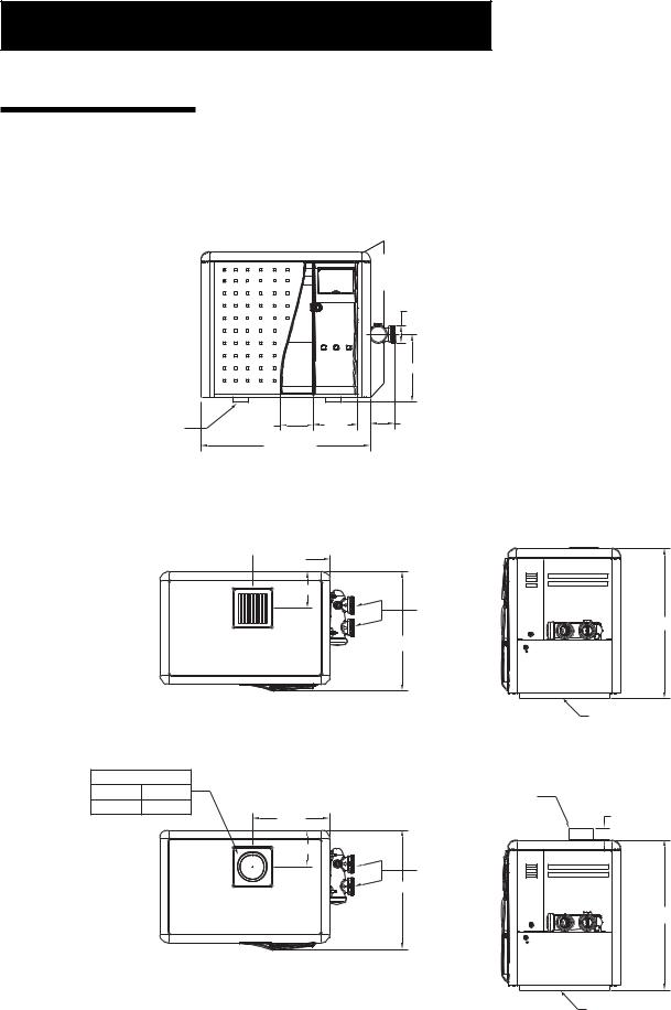
SPECIFICATIONS
These installation instructions are designed for use by qualified personnel only, trained especially for installation of this type of heating equipment and related components. Some states require installation and repair by licensed personnel. If this applies in your state, be sure your contractor bears the appropriate license. See Figure 1 for Outdoor and Indoor Installations.
|
|
|
24.05 |
|
|
|
Heater |
|
|
|
Depth |
|
|
|
3.50 |
|
|
|
14.50 |
LEG |
6.64 |
8.84 |
4.88 |
|
|
"A" DIM. |
|
|
|
DIMENSIONS IN INCHES |
|
|
|
|
|
|
|
|
|
MODEL |
"A" DIM. |
|
|
|
|
|
|
200 |
21.63 |
|
|
|
|
|
|
250 |
24.63 |
|
|
|
|
|
|
300 |
27.63 |
|
|
|
|
|
|
400 |
34.13 |
|
|
|
|
|
|
OUTDOOR INSTALLATION
 15.50
15.50
7.35
2 in. SOCKET
30.63
24.05
LEG
INDOOR INSTALLATION
INDOOR VENT ADAPTOR |
|
|
|
P/N 460506 |
4 in. Kit |
VENT ADAPTOR |
|
|
|
|
|
P/N 460507 |
5 in. Kit |
(See Indoor Venting |
2.00 |
|
15.50 |
Instructions) |
|
|
7.35 |
|
|
|
|
2 in. SOCKET |
|
|
|
24.05 |
|
30.63
Figure 1.
LEG
Rev. E 4-19-05 |
P/N 472089 |
Section III. Installation |
8 |
|
|
|
|
TO |
PUMP |
|
|
POOL |
|
POOL |
|
FILTER |
|
MANUAL |
|
||
HEATER |
|
|
|
BY-PASS |
|
|
|
|
|
|
|
|
CHECK |
GATE |
|
|
VALVE |
|
|
|
VALVE |
|
|
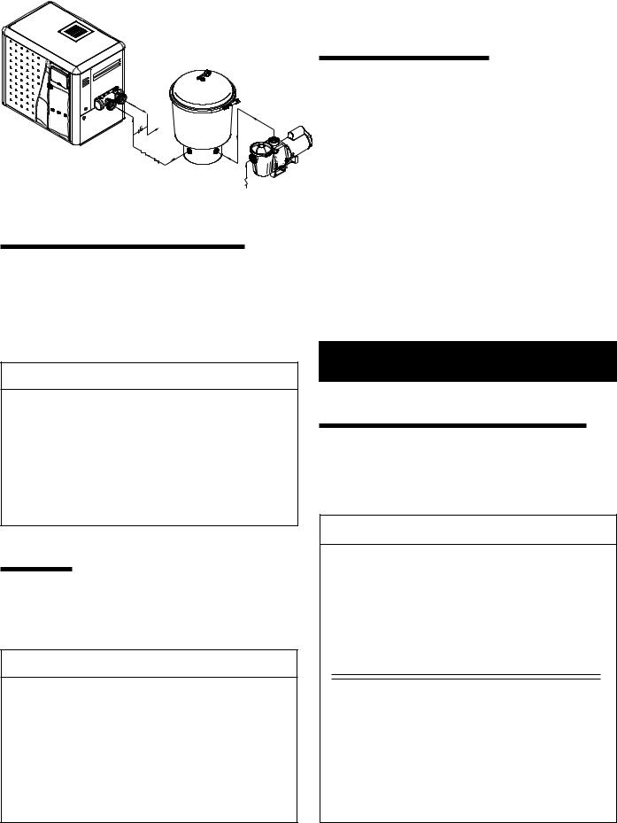
Figure 2. |
|
|
CHECK |
|
|
FROM |
|
|
|
|
VALVE |
|
|
|
POOL |
PLUMBING CONNECTIONS
The MiniMax NT LN heater has the unique capability of direct schedule 40 PVC plumbing connections. A set of bulkhead fittings is included with the MiniMax NT LN to insure conformity with Pentair’s recommended PVC plumbing procedure. Other plumbing connections can be used. See Figure 2 for plumbing connections.
 CAUTION
Before operating the heater on a new installation, turn on the circulation pump and bleed all the air from the filter using the air relief valve on top of the filter. Water should flow freely through the heater. Do not operate the heater unless water in the pool/spa is at the proper level. If a manual by-pass is installed, temporarily close it to insure that all air is purged from the heater.
VALVES
When any equipment is located below the surface of the pool or spa, valves should be placed in the circulation piping system to isolate the equipment from the pool or spa. Check valves are recommended to prevent back siphoning.
 CAUTION
Exercise care when installing chemical feeders so as to not allow back siphoning of chemical into the heater, filters or pump. When chemical feeders are installed in the circulation of the piping system, make sure the feeder outlet line is down stream of the heater, and is equipped with a positive seal noncorrosive “Check Valve”, (P/N R172288), between the feeder and heater.
MANUAL BY-PASS
Where the flow rate exceeds the maximum 120 GPM, a manual bypass should be installed and adjusted. After adjustments are made, the valve handle should be removed to avoid tampering. See Figure 2.
Model |
Min. (GPM) |
Max. (GPM) * |
|
|
|
|
|
200 |
20 |
120 |
|
|
|
|
|
250 |
30 |
120 |
|
|
|
|
|
300 |
30 |
120 |
|
|
|
|
|
400 |
40 |
120 |
|
|
|
|
|
* Do not exceed the maximum recommended |
|
||
flow rate for the connecting piping. |
|
||
|
|
|
|
|
|
Table 1. |
|
See page 30 for Pressure Relief Valve Installations.
BELOW POOL INSTALLATION
If the heater is below water level, the pressure switch must be adjusted. This adjustment must be done by a qualified service technician.
See following CAUTION before installation.
 CAUTION
BELOW OR ABOVE POOL INSTALLATION
The water pressure switch is set in the factory at 1½ PSI. This setting is for a heater installed at pool level or within 3’ above or 3’ below. If the heater is to be installed more that 3’ above or 3’ below, the water pressure switch must be adjusted by a qualified service technician. See page 22, Figure 21.
FLOW SWITCH
If the heater is installed more the 6’ above the pool or more than 10’ below the pool level, you will be beyond the limits of the pressure switch and a flow switch must be installed. Locate and install the flow switch externally on the outlet piping from the heater, as close as possible to the heater. Connect the flow switch wires in place of the water pressure switch wires.
P/N 472089 |
Rev. E 4-19-05 |
Section III. Installation |
9 |
|
|
WATER CONNECTIONS
Reversing Headers —
Reversible Inlet/Outlet Connection
The MiniMax NT LN Series heater is factory assembled with right side inlet/outlet water connections. The inlet/outlet header can be reversed for left side water connections without removing the heat exchanger.
Reversing Water Connections
Tools required:
Phillips Screw Driver
9/16 in. Socket and Wrench 1/2 in. & 9/16 in. Open Wrench
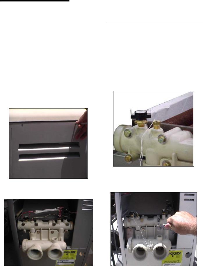
1.Remove the right and left large access doors. It is not necessary to remove the top of the heater to gain access to the headers.
2.Disconnect all wires from the high-limit switches except the short jumper wire.
NOTE
Do NOT remove the high-limit and pressure switches or the thermistor from the front header during the reversing procedure, as they will be in the proper location when installed on the left side.
3.Disconnect the water pressure switch wiring.
4.Disconnect the temperature sensor wires from the circuit board and feed them back to the header.
5.Remove the 8 bolts holding the main inlet/outlet head.
Rev. E 4-19-05 |
P/N 472089 |

Section III. Installation |
10 |
|
|
Reversible Inlet/Outlet Connection, cont’d.
On the MiniMax NT LN Series heater there is insulation installed by the factory on the return head side of the heaters. This insulation is there so that if the heads are reversed in the field, during initial installation of the heater, the high limits will be insulated from the heat radiating from the flue collector.
6.Return head in position before removal. This view shows the insulation installed by the factory. Remove the 8 bolts holding the return head in place.
7.When heads are removed, replace the heat exchanger tube seal gaskets.
8.Exchange the inlet/outlet header with the return header. Lift the insulation to allow the main head to be installed. Align header with the heat exchanger. When head is placed into position, release the insulation; it will now shield the high limits from the heat produced by the flue collector. Install header bolts, and tighten snugly by hand. (This will help avoid cross threading.) When tightening, use a cross pattern starting from the center of the header. DO NOT over tighten.
9.Install the temperature sensing probe by passing the wires through the hole provided on the left side of the brace panel. Route wires through the support bracket.
10.Reconnect all the high limit wires and the pressure switch wiring, routing the wires through the same hole as the thermostat sensor wires.
11.Pump and bleed system to check the head for leaks.
12.Reinstall the two large inspection plates on the appropriate side.
Remember: The inlet and outlet markings on the header are still correct.
Do not plumb the heater backwards.
P/N 472089 |
Rev. E 4-19-05 |
Section III. Installation |
11 |
|
|
GAS CONNECTIONS
GAS LINE INSTALLATIONS
Before installing the gas line, be sure to check which gas the heater has been designed to burn. This is important because different types of gas require different gas pipe sizes. The rating plate on the heater will indicate which gas the heater is designed to burn. The tables, shown on page 12, show which size pipe is required for the distance from the gas meter to the heater. The table is for natural gas at a specific gravity of .65.
When sizing gas lines, calculate three (3) additional feet of straight pipe for every elbow used. When installing the gas line, avoid getting dirt, grease or other foreign material in the pipe as this may cause damage to the gas valve, which may result in heater failure.
The gas meter should be checked to make sure that it will supply enough gas to the heater and any other appliances that may be used on the same meter. The gas line from the meter will usually be of a larger size than the gas valve supplied with the heater. Therefore a reduction of the connecting gas pipe will be necessary. Make this reduction as close to the heater as possible.
The heater and any other gas appliances must be disconnected from the gas supply piping system during any pressure testing on that system, (greater that ½ PSI). The heater and its gas connection must be leak tested before placing the heater in operation. Do not use flame to test the gas line. Use soapy water or another nonflammable method.
NOTE
A manual main shut-off valve must be installed externally to the heater.
 WARNING
DO NOT INSTALL THE GAS LINE UNION INSIDE THE HEATER CABINET. THIS WILL VOID YOUR WARRANTY.
SEDIMENT TRAPS
Install a sediment in front of the gas controls. The sediment trap shall be either a tee fitting with a capped nipple in the bottom outlet which can be removed for cleaning, as illustrated in Figure 3, or a other device recognized as an effective sediment trap. All gas piping should be tested after installation in accordance with local codes.
|
GAS |
GAS |
VALVE |
|
|
SUPPLY |
UNION |
|
TEE |
|
FITTING |
MANUAL |
|
SHUT OFF |
3 INCHES |
VALVE |
MINIMUM |
|
|
NIPPLE |
HEATER CABINET |
CAP |
|
Figure 3.
Rev. E 4-19-05 |
P/N 472089 |
 Loading...