


1 1
MiniMax® CH
POOL & SPA HEATERS
OPERATION & INSTALLATION MANUAL
 WARNING
FOR YOUR SAFETY - READ BEFORE OPERATING Warning: If you do not follow these instructions exactly, a fire or explosion may
result, causing property damage, personal injury or loss of life. For additional free copies of this manual; call (800) 831-7133.
To
Consumer
Retain For
Future
Reference
U.S. Patent Numbers 6,295,980 5,318,007 - 5,228,618 5,201,307 - 4,595,825
 WARNING
Warning: Improper installation, adjustment, alteration, service or maintenance can cause property damage, personal injury or death. Installation and service must be performed by a qualified installer, service agency or the gas supplier.
For Your
Safety
WHAT TO DO IF YOU SMELL GAS
•Do not try to light any appliance.
•Do not touch any electrical switch; do not use any phone in your building.
•Immediately call your gas supplier from a neighbor's phone. Follow the gas supplier's instructions.
•If you cannot reach your gas supplier, call the fire department.
Do not store or use gasoline or other flammable vapors and liquids in the vicinity of this or other appliances.
|
|
Pentair Pool Products, Inc. |
|
|
|
1620 Hawkins Ave., Sanford, NC 27330 • (919) 774-4151 |
|
|
|
10951 W. Los Angeles Ave., Moorpark, CA 93021 • (805) 523-2400 |
|
|
|
|
|
Rev. B 1-17-03 |
P/N 472128 |
||
|
2 |
Table of Contents |
|
Introduction ............................................................................................................... |
3 |
Important Notices ...................................................................................................................................................................... |
3 |
Warranty Information ................................................................................................................................................................. |
4 |
Operation .................................................................................................................... |
4 |
Safety Rules .............................................................................................................................................................................. |
4 |
Millivolt Lighting/Operation - Natural & Propane ........................................................................................................................ |
5 |
Operating (Controls) .................................................................................................................................................................. |
6 |
Maintenance ............................................................................................................... |
7 |
Maintenance Instructions ........................................................................................................................................................... |
7 |
Relief Valve ................................................................................................................................................................................ |
7 |
Energy Saving Tips .................................................................................................................................................................... |
7 |
Spring and Fall Operation .......................................................................................................................................................... |
7 |
Winter Operation ....................................................................................................................................................................... |
7 |
Chemical Balance ...................................................................................................................................................................... |
8 |
Installation Instructions ............................................................................................ |
9 |
Specifications .......................................................................................................................... |
9 |
Plumbing Connections ........................................................................................................... |
10 |
Plumbing/Valves ........................................................................................................................................................................ |
10 |
Manual Bypass .......................................................................................................................................................................... |
10 |
Below Pool Installation .............................................................................................................................................................. |
10 |
Water Connections.................................................................................................................. |
11 |
Reverse Water Connections ...................................................................................................................................................... |
11 |
Insulating High Limits when Reversing Heads ........................................................................................................................... |
11 |
Gas Connections..................................................................................................................... |
12 |
Gas Line Installation .................................................................................................................................................................. |
12 |
Pipe Sizing Chart/Gas Pressure Requirements ......................................................................................................................... |
12 |
Pipe Sizing Chart/Propane 2 Stage Regulation ......................................................................................................................... |
13 |
Regulated Manifold Pressure Test ............................................................................................................................................. |
13 |
Ventilation ................................................................................................................................ |
14 |
Outdoor Installation Requirements ............................................................................................................................................ |
14 |
Outdoor Cap Installation ............................................................................................................................................................ |
14 |
Indoor Installation Requirements ............................................................................................................................................... |
15 |
Installation on Floors Constructed of Combustible Materials ..................................................................................................... |
16 |
Indoor Draft Hood Installation .................................................................................................................................................... |
16 |
Electrical .................................................................................................................................. |
17 |
Millivolt Wiring Diagram ............................................................................................................................................................. |
17 |
Trouble Shooting (General) ....................................................................................... |
18 |
MiniMax CH Parts List & Exploded View ................................................................. |
19-21 |
MiniMax CH (150 IID Model) Appendix ..................................................................... |
A1-A9 |
MiniMax CH (150 IID Model) Parts List & Exploded View ....................................... |
A10-A12 |
Warranty Information ................................................................................................. |
Back Cover |
P/N 472128 |
Rev. B 1-17-03 |

3
Introduction
MiniMax CH
Pool and Spa Heaters
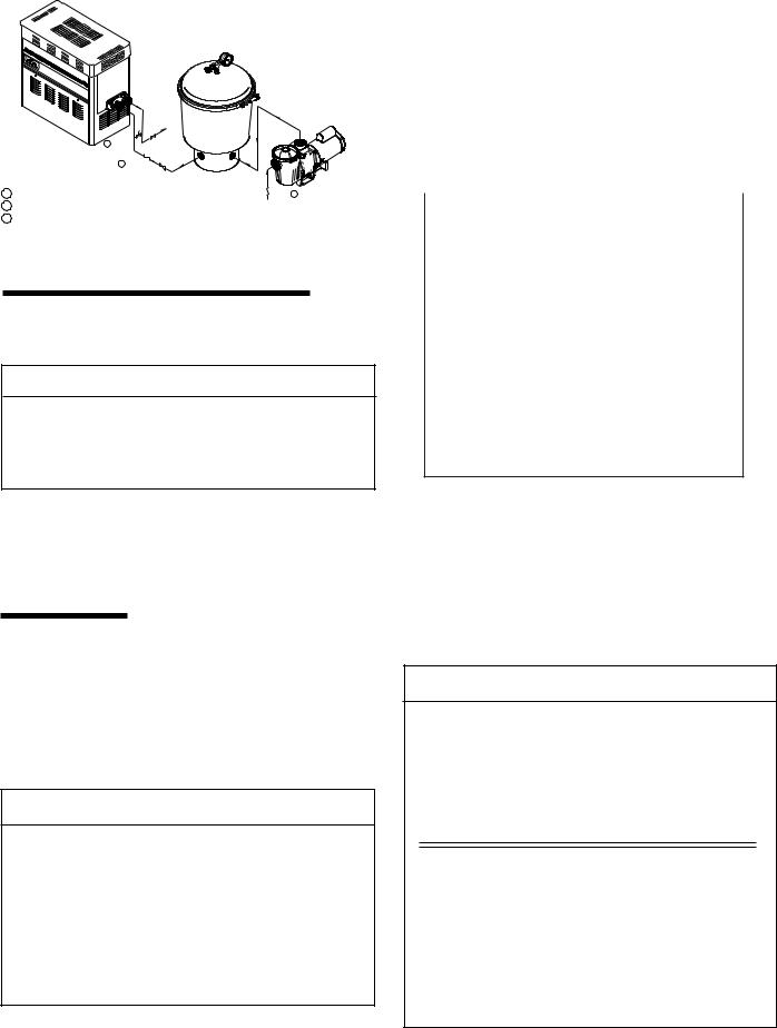
Congratulations on your purchase of a MiniMax CH high performance heating system. Proper installation and service of your new heating system and correct chemical maintenance of the water will ensure years of enjoyment. The MiniMax CH is a compact, lightweight and efficient gas fired high performance pool and spa heater that can be directly connected to schedule 40 PVC pipe and has a built-in top. The MiniMax CH is a millivolt heater and has a self sustaining pilot and requires NO external power source.
IMPORTANT NOTICES
...For the installer and operator of the MiniMax CH pool and spa heater. The manufacturer’s warranty may be void if, for any reason, the heater is improperly installed and/or operated. Be sure to follow the instructions set forth in this manual. If you need any more information, or if you have any questions regarding to this pool heater, please contact Pentair Pool Products, Inc. at (800) 831-7133.
These heaters are designed for the heating of swimming pools and spas, and should never be employed for use as space heating boilers, general purpose water heaters, in non-stationary installations, or for the heating of salt water.
 CAUTION
OPERATING THIS HEATER CONTINUOUSLY AT WATER TEMPERATURE BELOW 68° F. WILL CAUSE HARMFUL CONDENSATION AND WILL DAMAGE THE HEATER AND WILL VOID THE WARRANTY.
Do not use the heater to protect pools or spas from freezing if the final maintenance temperature desired is below 68° F. as this will cause condensation related problems.
CODE REQUIREMENTS
The installation must conform with local codes or in the absence of local codes with the latest
National Fuel Gas Code, ANSI Z223.1, and the latest edition of the National Electrical Code, NFPA 70.
Installation in Canada to be made in accordance with the latest CAN/CGA-B149.1 or .2 and CSA C22.1 Canadian Electric Code, part 1.
Rev. B 1-17-03 |
|
P/N 472128 |
|
Operation (contd.) |
4 |
|
|
This instruction manual provides operating instructions, installation and service information for the MiniMax CH high performance heater. The information in this manual applies to the MiniMax CH 150, 200, 250, 300, 350, and 400 natural gas and propane (LP) models.
It is very important that the owner/installer read and understand the section covering installation instructions, and recognize the local and state codes before installing the MiniMax CH. History and experience has shown that most heater damage is caused by improper installation practices.
WARRANTY INFORMATION
The MiniMax CH pool heater is sold with a limited factory warranty. Specific details are described on the back cover of this manual and a copy of the warranty and warranty registration card are included with the product. Return the warranty registration card after filling in the serial number from the rating plate inside the heater.
Pentair Pool Products’ high standards of excellence include a policy of continuous product improvement resulting in your state-of-the-art heater. We reserve the right to make improvements which change the specifications of the heater without incurring an obligation to update the current heater equipment.
Operation


 SAFETY RULES
1.Spa or hot tub water temperatures should never exceed 104° F (40° C). A temperature of 100° F (38° C) is considered safe for a healthy adult. Special caution is suggested for young children.
2.Drinking of alcoholic beverages before or during spa or hot tub use can cause drowsiness which could lead to unconsciousness and subsequently result in drowning.
3.Pregnant women beware! Soaking in water above 102° F (39° C) can cause fetal damage during the first three months of pregnancy (resulting in the birth of a brain-damaged or deformed child). Pregnant women should stick to the 100° F (38° C) maximum rule.
4.Before entering the spa or hot tub, the user should check the water temperature with an accurate thermometer. Spa or hot tub thermostats may err in regulating water temperatures by as much as 4° F (2.2° C).
5.Persons with a medical history of heart disease, circulatory problems, diabetes or blood pressure problems should obtain their physician's advice before using spas or hot tubs.
6.Persons taking medication which induce drowsiness, such as tranquilizers, antihistamines or anticoagulants should not use spas or hot tubs.
 WARNING
Should overheating occur or the gas supply fail to shut off, turn off the manual gas control valve to the appliance. Do not use this heater if any part has been under water. Immediately call a qualified service technician to inspect the heater and to replace any part of control system and gas control which has been under water.
P/N 472128 |
Rev. B 1-17-03 |
Operation (contd.) |
5 |
MINIMAX CH MILLIVOLT LIGHTING/OPERATION-NATURAL GAS & PROPANE
FOR YOUR SAFETY: READ BEFORE LIGHTING
 WARNING
If you do not follow these instructions exactly, a fire or explosion may result causing personal injury, loss of life and property damage.
Since propane gas is heavier than air, escaping propane will accumulate and remain at ground level. Do not attempt to light the heater. If you suspect a propane leak, lighting the heater can result in a fire or explosion which can cause personal injury, death, and property damage.
A.This heater is equipped with a pilot which must be lighted manually. When lighting the pilot, follow these instructions exactly.
B.BEFORE LIGHTING smell all around the heater area for gas. Be sure to smell next to the floor because some gas is heavier than air and will settle on the floor.
WHAT TO DO IF YOU SMELL GAS
-Do not try to light any heater.
-Do not touch any electrical switch; do not use any phone in your building.
-Immediately call your gas supplier from a neighbor's phone. Follow the gas supplier's instructions.
-If you cannot reach your gas supplier, call the Fire Department.
C.Use only your hand to push in or turn the gas control knob. Never use tools. If the knob will not push in or turn by hand, don't try to repair it. Call a qualified service technician. Forced or attempted repair may result in a fire or explosion.
D.Do not use this heater if any part has been under water. Immediately call a qualified service technician to inspect the heater and to replace any part of the control system and any gas control which has been under water.
LIGHTING INSTRUCTIONS
1.STOP! Read the safety information above.
2.Set the thermostat to the lowest setting.
3.Turn off electric power to the heater.
4.Push in gas control knob slightly and turn clockwise  to “OFF”.
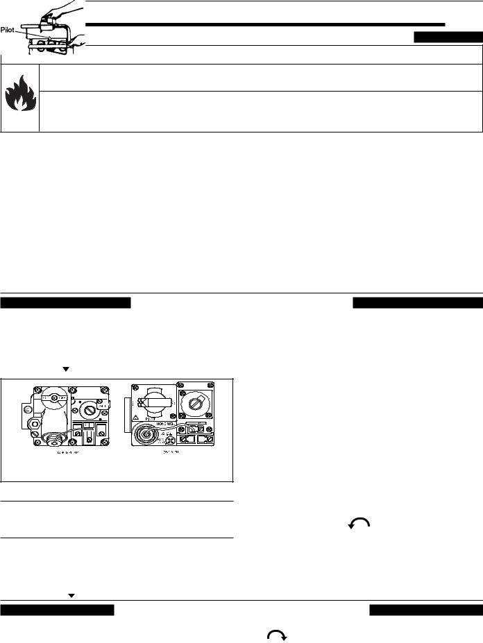
Robertshaw Millivolt Gas Valve |
Honeywell Millivolt Gas Valve |
Figure 1. |
Figure 2. |
Gas control knobs shown in “OFF” position.
NOTE
Knob cannot be turned from “Pilot to “OFF”” unless knob is pushed in slightly. DO NOT FORCE.
5.Wait five (5) minutes to clear out any gas. If you then smell gas, STOP! Follow "B" in the safety information above. If you don't smell gas, go to the next step.
6.Push in gas control knob slightly and turn counterclockwise  to “Pilot”.
7.Push the control knob all the way and hold in. Immediately light the pilot with Presslite matchless ignition system by pressing the red igniter button (located at the panel next to the gas valve). Continue to hold the control knob in for about one (1) minute after the pilot is lit. Release knob and it will pop back up. Pilot should remain lit. If it goes out, repeat steps 4 through 7.
•If knob does not pop up when released, stop and immediately call your service technician or gas
supplier.
•If the pilot will not stay lit after several tries, turn the gas control knob to “OFF” and call your service technician or gas supplier.
8.Turn knob on gas control counterclockwise to “ON”.
9.Replace the control access door.
10.Set the thermostat to the
desired setting. |
Figure 4. Pilot |
TO TURN OFF GAS TO HEATER
1.Set the thermostat to lowest setting.
2.Turn off all electric power to the heater if service is to be performed.
3.Remove control access door.
4. Push in gas control knob slightly and turn clockwise to "OFF". Do not force.
5. Replace control access door.
Rev. B 1-17-03 |
P/N 472128 |
Operation (contd.) |
6 |
|
|
OPERATING (CONTROLS) |
|
|
|
|
|
|
|
|
|
|
|
|
|
|
|
|
|
|
|
|
|
|
|
|
|
|
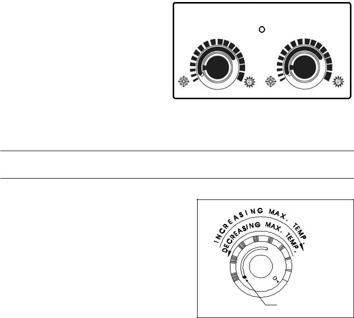
Dual Temperature Control System |
|
|
|
|
|
|
|
|
For convenience and economy all MiniMax CH |
|
|
|
|
|
|
|
|
heaters are equipped with two thermostats on the |
|
|
|
|
|
|
|
|
front of the heater control panel; see Figure 5. |
POOL |
|
|
|
|
|
SPA |
|
THERMOSTAT KNOB STOPPER |
|
|
|
|
|
|
|
|
|
|
|
|
|
|
|
||
|
|
|
OFF |
|||||
Each thermostat is equipped with a mechanical |
|
|
|
|||||
|
|
|
|
|
|
|
||
stop that can be locked or unlocked with use of a |
|
|
|
|
|
|
|
|
screwdriver to prevent temperatures in excess of |
|
|
|
|
|
|
|
|
that desired by the user; see Figure 6. |
|
|
|
|
|
|
|
|
The maximum setting can be adjusted by |
COLD POOL TEMP |
HOT COLD SPA TEMP HOT |
||||||
loosening the screw "A" and turning the stopper |
||||||||
dial to desired maximum setting. Lock the setting |
|
|
|
|
|
|
Figure 5. |
|
by tightening the screw. The Mechanical stop is |
|
|
|
|
|
|
|
|
under the knob. Ensure that the knob is stopping at the correct position when the knob is rotated clockwise from a lower temperature position. (See Thermostat Adjustment.)
NOTE
To eliminate error due to piping heat losses, measure pool temperature with an accurate thermometer directly at the pool or spa.
THERMOSTAT ADJUSTMENT
The knob with locking feature eliminates the need for constant thermostat adjustments. Set the knob pointer to the desired pool or spa temperature.
If further adjustment is needed, rotate the knob until the desired temperature is obtained. This knob position corresponding to your desired maximum pool or spa temperature may now be preset (locked) by the knob stopper which prevents the knob from being turned beyond the maximum temperature you set.
POWER (THERMOSTAT SELECT) SWITCH
The Pool/Off/Spa switch allows the heater to be turned off when heating is not desired.
Figure 6.
 Knob Stopper
Screw A
1.“Pool” position - Maintains selected pool temperature.
2.“Off” position - Heater will not come on regardless of drop in pool or spa temperature.
3.“Spa” position - This allows separate control of spa water temperature or an alternate lower pool temperature.
P/N 472128 |
Rev. B 1-17-03 |
7
Maintenance
MAINTENANCE INSTRUCTIONS
It is recommended that you check the following items at least every six months and at the beginning of every swimming season.
1.Examine the venting system. Make sure there are no obstructions in the flow of combustion and ventilation air.
2.Visually inspect the main burner and the pilot burner flame. The normal color of the flame is blue. When flame appears yellow, burners should be inspected and cleaned; see Figure 8.
3.Keep the heater area clear and free from combustibles and flammable liquids.
Blue Flame
Figure 7. |
Figure 8. |
 CAUTION
REMOVE THE FLOW VALVE ASSEMBLY WHEN DRILLING THE HOLE TO INSTALL A PRV. OTHERWISE, YOU WILL DRILL INTO THE VALVE ASSEMBLY.
Pressure Relief Valve
In some installations, a pressure relief valve (PRV) is required on the MiniMax CH heater. To install a PRV, carefully drill a 3/8 in. hole in center of 3/4 in. NPT port (on main header) being careful to drill only thru wall at bottom
of 3/4 in. NPT port and no deeper—now thread
in the 3/4 NPT PRV. (Sold separately.)
FOR PRV INSTALLATION DRILL THRU THE NPT PORT
ENERGY SAVING TIPS
1.If possible, keep pool or spa covered when not in use. This will not only cut heating costs, but also keep dirt and debris from settling in the pool and conserve chemicals.
2.Reduce the pool thermostat setting to 78° F. or lower. This is accepted as being the most healthy temperature for swimming by the American Red Cross.
3.Use an accurate thermometer.
4.When the proper maximum thermostat settings have been determined, tighten the thermostat knob stopper.
5.Set time clock to start circulation system no earlier than daybreak. The swimming pool loses less heat at this time.
6.For pools that are only used on the weekends, it is not necessary to leave the thermostat set at 78° F. Lower the temperature to a range that can be achieved easily in one day. Generally, this would be 10° F. to 15° F., if pool heater is sized properly.
7.During the winter or while on vacation, turn the heater off.
8.Set up a regular program of preventative maintenance for the heater each new swimming season. Check heat exchanger, controls, burners, operation, etc.
SPRING AND FALL OPERATION
If the pool is being used occasionally, do not turn the heater completely off. Set the thermostat down to 65° F. This will keep the pool and the surrounding ground warm enough to bring the pool up to a comfortable swimming temperature in a shorter period of time.
WINTER OPERATION
 CAUTION
OPERATING THIS HEATER CONTINUOUSLY AT WATER TEMPERATURE BELOW 68° F. WILL CAUSE HARMFUL CONDENSATION AND WILL DAMAGE THE HEATER AND WILL VOID THE WARRANTY.
If the pool won't be used for a month or more, turn the heater off at the main gas valve. For areas where there is no danger of water freezing, water should circulate through the heater all year long, even though you are not heating your swimming pool. The MiniMax CH should not be operated out doors at temperatures below 0° F. for propane and -20° F. for natural gas. Where freezing is possible, it is necessary to drain the water from the heater. This may be done by opening the drain valve located at the inlet/outlet header (see Figure 9.) allowing all water to drain out of the heater. It would be a good practice to use compressed air to blow the water out of the heat exchanger. (See additional notes under Important Notices in Introduction on page 3.)
Rev. B 1-17-03 |
P/N 472128 |

Maintenance (contd.) |
8 |
CHEMICAL BALANCE
RULE: 7.4 to 7.6 is a desirable pH range. It is essential to maintain correct pH, see Table 2.
POOL AND SPA WATER
Your Pentair Pool Products pool heater was designed specifically for your spa or pool and will give you many years of trouble free service provided you keep your water chemistry in proper condition.
Three major items that can cause problems with your pool heater are improper pH, disinfectant residual, and total alkalinity. These items, if not kept properly balanced, can shorten the life of the heater and cause permanent damage.
 CAUTION
Heat exchanger damage resulting from chemical imbalance is not covered by the warranty.
WHAT A DISINFECTANT DOES
Two pool guests you do not want are algae and bacteria. To get rid of them and make pool water sanitary for swimming - as well as to improve the water's taste, odor and clarity - some sort of disinfectant must be used.
Chlorine and bromine are universally approved by health authorities and are accepted disinfecting agents for bacteria control.
WHAT IS A DISINFECTANT RESIDUAL?
When you add chlorine or bromine to the pool water, a portion of the disinfectant will be consumed in the process of destroying bacteria, algae and other oxidizable materials. The disinfectant remaining is called chlorine residual or bromine residual. You can determine the disinfectant residual of your pool water with a reliable test kit, available from your local pool supply store.
You must maintain a disinfectant residual level adequate enough to assure a continuous kill of bacteria or virus introduced into pool water by swimmers, through the air, from dust, rain or other sources.
It is wise to test pool water regularly. Never allow chlorine residual to drop below 0.6 ppm (parts per million). The minimum level for effective chlorine or bromine residual is 1.4 ppm.
pH - The term pH refers to the acid/alkaline balance of water expressed on a numerical scale from 0 to 14. A test kit for measuring pH balance of your pool water is available from your local pool supply store; see Table 1.
Table 1. |
|
|
|
pH Chart |
|
|
|
|
|
|||||
|
|
|
|
|
|
|
||||||||
Strongly Acid |
|
|
|
Neutral |
|
Strongly Alkaline |
||||||||
0 |
1 |
2 |
3 |
4 |
5 |
6 |
7 |
8 |
9 |
10 |
11 |
12 |
13 |
14 |
Muriatic Acid has a pH of about 0. Pure water is 7 (neutral). Weak Lye solution have a pH of 13-14.
If pH becomes too high (over alkaline), it has these effects:
1.Greatly lowers the ability of chlorine to destroy bacteria and algae.
2.Water becomes cloudy.
3.There is more danger of scale formation on the plaster or in the heat exchanger.
4.Filter elements may become blocked.
If pH is too low (over acid) the following conditions may occur:
1.Excessive eye burn or skin irritation.
2.Etching of the plaster.
3.Corrosion of metal fixtures in the filtration and recirculation system, which may create brown, blue, green, or sometimes almost black stains on the plaster.
4.Corrosion of copper in the heater, which may cause leaks.
5.If you have a sand and gravel filter, the alum used as a filter aid may dissolve and pass through the filter.
CAUTION: Do not test for pH when the chlorine residual is 3.0 ppm or higher, or bromine residual is 6.0 ppm or higher. See your local pool supply store for help in properly balancing your water chemistry.
RULE: Chemicals that are acid lower pH. Chemicals that are alkaline raise pH.
Table 2. |
|
pH Control Chart |
|
|
|
|||
|
|
|
|
|
|
|
|
|
6.8 |
7.0 |
7.2 |
7.4 |
7.6 |
7.8 |
8.0 |
8.2 |
8.4 |
Add Soda, Ash or |
Marginal |
Ideal |
Marginal |
Add Acid |
||||
Sodium Bicarbonate |
|
|
|
|
|
|
|
|
|
|
|
|
|
|
|
|
|
ALKALINITY High - Low:
"Total alkalinity" is a measurement of the total amount of alkaline chemicals in the water, and control pH to a great degree. (It is not the same as pH which refers merely to the relative alkalinity/acidity balance.) Your pool water's total alkalinity should be 100 - 140 ppm to permit easier pH control.
A total alkalinity test is simple to perform with a reliable test kit. You will need to test about once a week and make proper adjustments until alkalinity is in the proper range. Then, test only once every month or so to be sure it is being maintained. See your local pool dealer for help in properly balancing the water chemistry.
P/N 472128 |
Rev. B 1-17-03 |

9
Installation Instructions
SPECIFICATIONS
IMPORTANT NOTICE: These installation instructions are designed for use by qualified personnel only, trained especially for installation of this type of heating equipment and related components. Some states require installation and repair by licensed personnel. If this applies in your state, be sure your contractor bears the appropriate license.
Outdoor installation - stackless
Model |
"A" Dim |
"B" Dim |
|
|
|
150 |
17 7/8 in. |
6½ in. |
|
|
|
200 |
20 7/8 in. |
9½ in. |
|
|
|
250 |
23 7/8 in. |
12½ in. |
|
|
|
300 |
26 7/8 in. |
15½ in. |
|
|
|
350 |
29 7/8 in. |
18½ in. |
|
|
|
400 |
33 3/8 in. |
22 3/8 in. |
|
|
|
|
|
Table 3. |
Outdoor installation - with vent kit
Model |
"A" Dim |
"B" Dim |
"C" Dim |
"D" Dim |
|
|
|
|
|
150 |
17 7/8 in. |
6½ in. |
7¾ in. |
39¾ in. |
|
|
|
|
|
200 |
20 7/8 in. |
9½ in. |
10 in. |
42¾ in. |
|
|
|
|
|
250 |
23 7/8 in. |
12½ in. |
10 in. |
42¾ in. |
|
|
|
|
|
300 |
26 7/8 in. |
15½ in. |
10¼ in. |
43¾ in. |
|
|
|
|
|
350 |
29 7/8 in. |
18½ in. |
13 in. |
47¾ in. |
|
|
|
|
|
400 |
33 3/8 in. |
22 3/8 in. |
17 in. |
51¾ in. |
|
|
|
|
|
|
|
|
|
Table 4. |
OFF |
CH |
|
|
32 |
|
|
|
13 |
7 |
|
|
|
|
8 |
|
5 |
1 |
"B" DIM. |
|
|
|
2 |
|
|
1 |
|
|
"A" DIM. |
21 |
|
|
|
4.875 |
2 |
|
|
|
|
||
|
|
FRONT VIEW |
SIDE VIEW |
|
"C" |
|
"E" DIM. |
DIM. |
|
|
"D" |
|
|
DIM |
|
|
|
OFF |
CH |
|
|
|
28" |
|
|
|
|
|
|
|
|
|
|
|
|
|
|
|
|
|
|
|
|
|
|
|
|
|
|
|
|
|
5 |
1 |
|
|
|
|
"B" DIM. |
|
|
|
|
|
|
|
|
|
|
|
|
||
|
|
|
|
2 |
|
|
|
|
|
"A" DIM. |
|
|
|
|
|
|
|
|
|
|
211 |
||
|
|
|
|
|
|
|
|
|
|
|
|
|
|
|
2 |
||||||||
|
|
|
|
|
|
|
|
|
|
|
"E" DIM. |
|
|
|
4.875 |
|
|||||||
|
|
|
|
|
|
|
|
|
|
|
|
|
|
|
|||||||||
|
|
|
|
|
|
|
|
|
|
|
|
|
|
|
|
|
|
|
|
|
|
||
Indoor installation - stack (USA only) Outdoor shelter installation (Canada)
Model |
|
"A" Dim |
"B" Dim |
"C" Dim |
"D" Dim |
"E" Dim |
|
|
|
|
|
|
|
150 |
|
17 7/8 in. |
6½ in. |
13 in. |
52¾ in. |
6 in. |
|
|
|
|
|
|
|
200 |
|
20 7/8 in. |
9½ in. |
13 in. |
53 7/8 in. |
7 in. |
|
|
|
|
|
|
|
250 |
|
23 7/8 in. |
12½ in. |
13 in. |
53 7/8 in. |
7 in. |
|
|
|
|
|
|
|
300 |
|
26 7/8 in. |
15½ in. |
13 in. |
55 in. |
8 in. |
|
|
|
|
|
|
|
350 |
|
29 7/8 in. |
18½ in. |
13 in. |
56 in. |
9 in. |
|
|
|
|
|
|
|
400 |
|
33 3/8 in. |
22 3/8 in. |
17 in. |
60¾ in. |
10 in. |
|
|
|
|
|
|
|
|
|
|
|
|
|
Table 5. |
Rev. B |
1-17-03 |
|
|
|
|
|
"C" |
|
|
|
|
DIM. |
|
|
|
|
"D" |
|
|
|
|
DIM |
|
|
|
|
|
|
OFF |
CH |
|
|
|
|
|
|
28 |
|
|
|
|
107 |
|
|
13 |
7 |
|
|
|
8 |
|
8 |
|
|
|
|
GAS LINE |
5 |
1 |
"B" DIM. |
|
2 |
|
1 |
||
OPENING |
|
|
|
|
|
|
"A" DIM. |
212 |
|
|
|
|
||
|
|
|
4.875 |
|
P/N 472128
Installation (contd.) |
10 |
|
|
|
|
|
TO |
|
PUMP |
|
|
|
POOL |
|
|
POOL |
|
MANUAL |
|
FILTER |
|
3 |
ISOLATION |
|
|
||
HEATER |
BY-PASS |
|
|
||
VALVE |
|
|
|||
|
|
1 CHECK |
|
|
|
|
|
VALVE |
|
|
|
|
|
|
ISOLATION |
|
|
|
|
|
VALVE |
|
|
1 Optional. |
|
|
|
VALVECHECK 2 |
|
2 Required when installation is below water level. |
FROM |
|
|||
POOL |
Figure 10. |
||||
3 Required when flow rates exceed 120 gpm. |
|
||||
PLUMBING CONNECTIONS
The MiniMax CH heater has the unique capability of direct schedule 40 PVC plumbing connections.
 CAUTION
Before operating the heater on a new installation, turn on the circulation pump and bleed all the air from the filter using the air relief valve on top of the filter. Water should flow freely through the heater.
Do not operate the heater unless water in the pool/ spa is at the proper level.
PLUMBING
VALVES
When any equipment is located below the surface of the pool or spa, valves should be placed in the circulation piping system to isolate the equipment from the pool or spa.
Check valves are recommended to prevent back siphon.
 CAUTION
Exercise care when installing chemical feeders so as to not allow back siphoning of chemical into the heater, filters or pump. When chemical feeders are installed in the circulation of the piping system, make sure the feeder outlet line is down stream of the heater, and is equipped with a positive seal non-corrosive “Check Valve”, (P/N R172288), between the feeder and heater.
MANUAL BY-PASS
Where the flow rate exceeds the maximum 120 GPM, a manual bypass should be installed and adjusted. After adjustments are made, the valve handle should be removed to avoid tampering.
Model |
Min. |
Max. * |
|
|
|
150 |
20 |
120 |
|
|
|
200 |
20 |
120 |
|
|
|
250 |
30 |
120 |
|
|
|
300 |
30 |
120 |
|
|
|
350 |
40 |
120 |
|
|
|
400 |
40 |
120 |
|
|
|
* Do not exceed the maximum recommended flow rate for the connecting piping.
Table 6.
BELOW POOL INSTALLATION
If the heater is below water level, the pressure switch should be adjusted. This adjustment must be done by a qualified service technician.
See following CAUTION.
 CAUTION
BELOW OR ABOVE POOL INSTALLATION
The water pressure switch is set in the factory at 1½ PSI. This setting is for a heater installed at pool level or within 3’ above or 3’ below. If the heater is to be installed more that 3’ above or 3’ below, the water pressure switch must be adjusted by a qualified service technician.
FLOW SWITCH
If the heater is installed more the 6’ above the pool or more than 10’ below the pool level, you will be beyond the limits of the pressure switch and a flow switch must be installed. Locate and install the flow switch externally on the outlet piping from the heater, as close as possible to the heater. Connect the flow switch wires in place of the water pressure switch wires.
P/N 472128 |
Rev. B 1-17-03 |
Installation (contd.) |
11 |
|
|
WATER CONNECTIONS
Reversible Inlet/Outlet Connection
The MiniMax CH heater is factory assembled with right side inlet/outlet water connections. The inlet/ outlet header can be reversed for left side water connections without removing the heat exchanger.
Reversing Water Connections Disassembly
Tools needed:
1/4 in Nut Driver
9/16 in. Socket and Wrench 1/2 in. & 9/16 in. Open Wrench
Screw Driver(s) - (Flathead & Phillips)
1.Remove the inspection plates.
2.Disconnect all wires from the high-limit switches except the short jumper wire. The exact order of the disconnection is not important.
NOTE
There is no reason to remove the high-limit and pressure switches or the thermister from the front header during the reversing procedure, as they will be in the proper location when installed on the left side.
3.Disconnect the pressure switch wiring.
4.Disconnect the thermostat thermister leads from the control board.
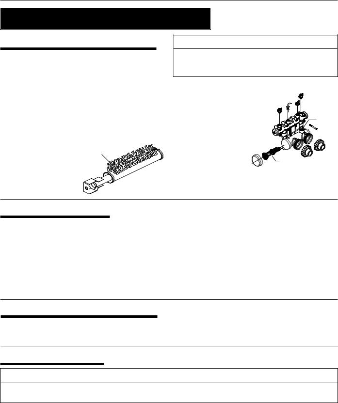
5.Exchange the in/out header with the return header. Replace the heat exchanger tube seals with new seals provided in the Quick-Flange Accessory Bag.
6.Install the temperature sensing bulb by passing the wires through the hole provided on the left side of the brace panel. Route wires through the support bracket.
7.Reconnect all the high limit wires. Reconnect the pressure switch wiring. Route the wires through the same hole as the thermostat sensor wires and reconnect thermister to the board.
8.Reinstall the inspection plates.
INSULATING THE HIGH LIMITS
When Reversing Heads on the MiniMax CH Heater
On the MiniMax CH heater there is insulation installed by the factory on the return head side of the heaters. This insulation is there so that if the heads are reversed in the field, during initial installation of the heater, the reflected heat from the flue collector will be insulated from the high limits.
Return head in position before removal.
This view shows the insulation installed by the factory.
Return head removed and new tube seals installed. Now ready to accept the installation of the main head.
Lift the installation to allow the main head to be installed. When head is placed into position, release the insulation; it will now shield the high limits from the heat produced by the flue collector.
Rev. B 1-17-03 |
P/N 472128 |
 Loading...