


IntelliFlo® VS-3050
Variable Speed Programmable Pump
(Compatible with IntelliComm® communication center and EasyTouch®, IntelliTouch® and SunTouch™ control systems)
AUTO |
HEATER |
SPA |
100°F/95°F |
AIR |
70°F |
MON |
09:30 AM |
Installation
and
User’s Guide
IMPORTANT SAFETY INSTRUCTIONS
READ AND FOLLOW ALL INSTRUCTIONS
SAVE THESE INSTRUCTIONS
Technical Support
Sanford, North Carolina (8 A.M. to 5 P.M. ET)
Moorpark, California (8 A.M. to 5 P.M. PT)
Phone: (800) 831-7133
Fax (800) 284-4151
Web sites: visit www.pentairpool.com and staritepool.com
Protected by U.S. Patents Pending
© 2008 Pentair Water Pool and Spa, Inc. All rights reserved This document is subject to change without notice
1620 Hawkins Ave., Sanford, NC 27330 • (919) 566-8000
10951 West Los Angeles Ave., Moorpark, CA 93021 • (805) 553-5000
Trademarks and disclaimers: IntelliComm®, EasyTouch®, IntelliTouch®, SunTouch™, IntelliFlo® and Pentair Water Pool and Spa® are trademarks and/or registered trademarks of Pentair Water Pool and Spa, Inc. and/or its affiliated companies in the United States and/or other counties. Teflon® is a registered trademark of E.I. Du Pont De Nemours and Company Corporation. Unless noted, names and brands of others that may be used in this document are not used to indicate an affiliation or endorsement between the proprietors of these names and brands and Pentair Water Pool and Spa, Inc. Those names and brands may be the trademarks or registered trademarks of those parties or others.
P/N 357269 (Rev C) - 3/12/08

|
|
i |
|
Contents |
|
Important Safety Precautions ........................................................................................... |
|
ii |
Section 1: IntelliFlo VS-3050 Overview ........................................................................... |
1 |
|
IntelliFlo VS-3050 Variable Speed Pump ............................................................................... |
|
1 |
IntelliFlo VS-3050 models ..................................................................................................... |
|
1 |
External Control .................................................................................................................... |
|
1 |
Features ............................................................................................................................... |
|
2 |
IntelliFlo Motor Assembly ...................................................................................................... |
|
2 |
IntelliFlo Drive Assembly and Control Panel ......................................................................... |
3 |
|
IntelliFlo Operator Control Panel ........................................................................................... |
|
4 |
Controls and LEDs .......................................................................................................... |
|
4 |
Section 2: Operating IntelliFlo VS-3050 ........................................................................... |
5 |
|
Setting the pump preset speed ............................................................................................ |
|
5 |
Adjusting the pump speed .................................................................................................... |
|
5 |
Starting the pump ................................................................................................................. |
|
6 |
Stopping the pump ................................................................................................................ |
|
6 |
Resetting the pump to factory defaults ................................................................................. |
|
6 |
Assigning a pump address for remote control...................................................................... |
6 |
|
Priming the pump for the first time or after service .............................................................. |
7 |
|
Priming the Pump ........................................................................................................... |
|
8 |
External Control with IntelliComm Communication Center .................................................. |
9 |
|
External Control Connection ........................................................................................... |
|
9 |
Connecting IntelliFlo to an EasyTouch System.................................................................... |
10 |
|
Connecting IntelliFlo to an IntelliTouch System .................................................................... |
13 |
|
Connecting IntelliFlo to a SunTouch System ....................................................................... |
15 |
|
Section 3: User Maintenance .......................................................................................... |
|
17 |
Pump Strainer Basket ......................................................................................................... |
|
17 |
Pump Strainer Basket Service ............................................................................................ |
|
17 |
Motor Service ...................................................................................................................... |
|
18 |
Winterizing .......................................................................................................................... |
|
19 |
Priming the pump after service ........................................................................................... |
|
19 |
Section 4: Installation and Removal ................................................................................ |
|
21 |
IntelliFlo VS-3050 Kit Contents ............................................................................................ |
|
21 |
Installing IntelliFlo ................................................................................................................. |
|
21 |
Location ............................................................................................................................... |
|
21 |
Piping................................................................................................................................... |
|
21 |
Check Valve ......................................................................................................................... |
|
21 |
Wiring the IntelliFlo .............................................................................................................. |
|
22 |
Pump Disassembly ............................................................................................................. |
|
23 |
Pump Reassembly/Seal Replacement ............................................................................... |
|
24 |
Shaft Seal Replacement...................................................................................................... |
|
24 |
Drive Assembly Removal and Installation ............................................................................ |
25 |
|
Illustrated Parts List ............................................................................................................. |
|
26 |
IntelliFlo Pump Dimensions ................................................................................................. |
|
27 |
IntelliFlo Flow and Power vs Flow Pump Curve .................................................................. |
27 |
|
IntelliFlo Electrical Specifications ......................................................................................... |
|
27 |
Section 5: Troubleshooting ............................................................................................. |
|
29 |
Warning and Alarm conditions ............................................................................................. |
|
29 |
Alarm and warning LED sequence ...................................................................................... |
|
29 |
General IntelliFlo Troubleshooting Problems ....................................................................... |
30 |
|
IntelliFlo VS-3050 Installation and User’s Guide
ii
IMPORTANT SAFETY PRECAUTIONS


 Important Notice:
Attention Installer: This manual contains important information about the installation, operation and safe use of this product. This information should be given to the owner and/or operator of this equipment.
WARNING — Before installing this product, read and follow all warning notices and instructions which are included. Failure to follow safety warnings and instructions can result in severe injury, death, or property damage. Call (800) 831-7133 for additional free copies of these instructions.
 WARNING — Entrapment Avoidance Notice:
The suction outlet connected to a swimming pool or spa pump can pull a high vacuum if it is blocked. Therefore, if only one suction outlet smaller than 18" x 23" is used, anyone blocking the suction outlet with their body can be trapped and held against the suction outlet. Disembowelment or drowning can result. Therefore, if small suction outlets are used with this pump, to prevent this entrapment and possible death, install at least two suction outlets in the body of water. Separate these suction outlets as described in the International Residential Code (IRC), the International Business Code (IBC), the Consumer Products Safety Council (CPSC) Guidelines for Entrapment Hazards:
Making Pools and Spas Safer or ANSI/IAF-7 Standard for Suction Entrapment Avoidance in Swimming Pools, Wading Pools, Spas, Hot Tubs and Catch Basins. If suction outlets are not used, additional entrapment avoidance measures as described in the CPSC Guidelines or ANSI/IAF-7 should be employed.
The covers used on suction outlets should be approved and listed as conforming to the currently published edition of ANSI/ASME A112.19.8 Standard covering Suction Fittings for Use in Swimming Pools, Wading Pools, Spas and Hot Tubs. These covers should be inspected regularly and replaced if cracked, broken or older than the design lifetime indicated on them by the manufacturer. The maximum possible flow rate of this pump should be less than or equal to the maximum approved flow rate indicated on the suction outlet cover by the manufacturer. THE USE OF UNAPPROVED COVERS OR ALLOWING USE OF THE POOL OR SPA WHEN COVERS ARE CRACKED OR BROKEN CAN RESULT IN HAIR ENTANGLEMENT WHICH CAN RESULT IN DEATH.
WARNING — Risk of electrical shock or electrocution.
This pool pump must be installed by a licensed or certified electrician or a qualified pool serviceman in accordance with the National Electrical Code and all applicable local codes and ordinances. Improper installation will create an electrical hazard which could result in death or serious injury to pool users, installers, or others due to electrical shock, and may also cause damage to property.
Always disconnect power to the pool pump at the circuit breaker before servicing the pump. Failure to do so could result in death or serious injury to serviceman, pool users or others due to electric shock.
IntelliFlo VS-3050 Installation and User’s Guide
iii
IMPORTANT SAFETY PRECAUTIONS (continued)
WARNING — Water temperature in excess of 100° Fahrenheit may be hazardous to your health. Prolonged immersion in hot water may induce hyperthermia. Hyperthermia occurs when the internal temperature of the body reaches a level several degrees above normal body temperature of 98.6° F. (37° C.). The symptoms of hyperthermia include: drowsiness, lethargy, dizziness, fainting, and an increase in the internal temperature of the body.
The effects of hyperthermia include: 1) Unawareness of impending danger. 2) Failure to perceive heat. 3) Failure to recognize the need to leave the spa. 4) Physical inability to exit the spa. 5) Fetal damage in pregnant women. 6) Unconsciousness resulting in danger of drowning.
WARNING — The use of alcohol, drugs, or medication can greatly increase the risk of fatal hyperthermia in hot tubs and spas.
WARNING — To reduce the risk of injury, do not permit children to use this product unless they are closely supervised at all times.
WARNING — For units intended for use in other than single-family dwellings, a clearly labeled emergency switch shall be provided as part of the installation. The switch shall be readily accessible to the occupants and shall be installed at least 5 feet (1.52 m) away, adjacent to, and within sight of, the unit.
WARNING — When setting up pool water turnovers or flow rates the operator must consider local codes governing turnover as well as disinfectant feed ratios.
WARNING — Before servicing the system, switch the main power OFF and remove the communication cable from the pump.
CAUTION — Install the pump a minimum of five (5) feet from the inside wall of the pool and spa. Canadian installations require a minimum of three (3) meters from pool water.
 CAUTION — A No. 8 AWG or larger conductor must be wired to the motor bonding lug.
CAUTION — This pump is for use with permanently installed pools and may also be used with hot tubs and spas if so marked. Do not use with storable pools. A permanently installed pool is constructed in or on the ground or in a building such that it cannot be readily disassembled for storage. A storable pool is constructed so that it may be readily disassembled for storage and reassembled to its original integrity and has a maximum dimension of 18 feet (5.49m) and a maximum wall height of 42 inches (1.07m).
CAUTION — For hot tubs and spa pumps, do not install within an outer enclosure or beneath the skirt of a hot tub or spa unless so marked.
CAUTION — IntelliFlo is capable of generating systems pressures up to 50 psi. Installers must ensure that all system components are rated to withstand at least 50 psi. Over pressurizing the system can result in catastrophic component failure or property damage.
General Installation Information
•All work must be performed by a licensed electrician, and must conform to all national, state, and local codes.
•Install to provide drainage of compartment for electrical components.
IntelliFlo VS-3050 Installation and User’s Guide
iv
IMPORTANT SAFETY PRECAUTIONS (continued)
General Installation Information
WARNING — Pumps improperly sized or installed or used in applications other than for which the pump was intended can result in severe personal injury or death. These risks may include but not be limited to electric shock, fire, flooding, suction entrapment or severe injury or property damage caused by a structural failure of the pump or other system component.
WARNING — The pump can produce high levels of suction within the suction side of the plumbing system. These high levels of suction can pose a risk if a person comes
within the close proximity of the suction openings. A person can be seriously
injured by this high level of vacuum or may become trapped and drown. It is absolutely critical that the suction plumbing be installed in accordance with the
latest national and local codes for swimming pools.
• These instructions contain information for a variety of pump models and therefore some instructions may not apply to a specific model. All models are intended for use in swimming pool applications. The pump will function correctly only if it is properly sized to the specific application and properly installed.
General Warnings
•Never open the inside or the drive motor enclosure. There is a capacitor bank that holds a 230 VAC charge even when there is no power to the unit.
•The IntelliFlo VS-3050 pump is not submersible
•The IntelliFlo VS-3050 pump is capable of 174 GPM or 104 feet of head; use caution when installing and programming to limit pumps performance potential with old or questionable equipment
•Code requirements for the electrical connection differ from state to state. Install equipment in accordance with the National Electrical Code and all applicable local codes and ordinances.
•Always Press the Stop button and disconnect the communication cable before performing maintenance, and always power the unit off by disconnecting the main circuit to the pump.
IntelliFlo VS-3050 Installation and User’s Guide
1
Section 1
Overview
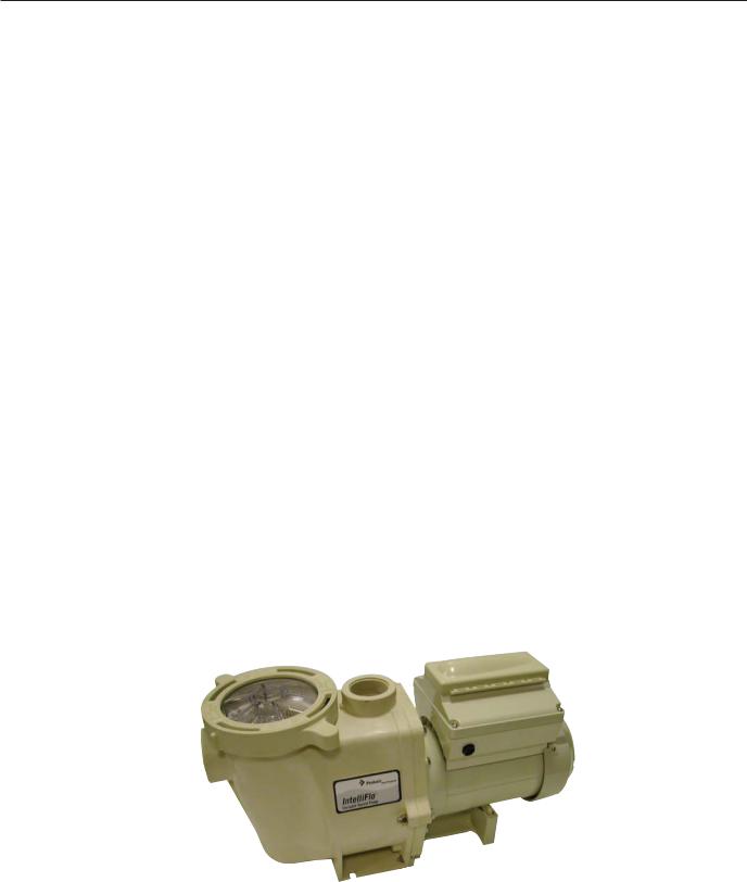
IntelliFlo® VS-3050 Variable Speed Pump
The IntelliFlo VS-3050 variable speed pump is well suited for all of your pool, spa, cleaner, waterfall and other water application. Using the control panel, IntelliFlo can use one of the four selectable preset speeds or the pump speed can be adjusted to run at a specific speed. IntelliFlo outperforms all conventional pumps in its class. Advanced energy conservation features ensure that your filtration system is operating at peak efficiency.
IntelliFlo VS-3050 models
The IntelliFlo VS-3050 operates at a maximum system flow of 160 gallons per minute (GPM)
The IntelliFlo VS-3050 can operate from 400 RPM to 3450 RPM with preset speeds of 750, 1500, 2350, and 3110 RPM. The pump can be adjusted from the control panel to run at any speed between 400 RPM to 3450 RPM for different applications. The IntelliFlo pump control panel alarm LED warns the user against under and over voltage, high temperature, over current and freeze protection. See page 29 for the LED alarm and warning sequence codes.
External Control
The IntelliFlo VS-3050 can communicate with an EasyTouch, IntelliTouch or SunTouch control system or the IntelliComm communication center via a two-wire RS-485 connection for remote speed control. The RS-485 communication cable is included with each pump. The EasyTouch and IntelliComm provide the ability to remotely control the IntelliFlo with four preset speeds. The IntelliTouch can be configured to use eight speeds with the IntelliFlo VS-3050.
IntelliFlo VS-3050 variable speed pump
IntelliFlo VS-3050 Installation and User’s Guide
2
Features
•Adjusts to various pool sizes
•Prevents thermal overload
•Detects and prevents damage from under and over voltage conditions
•Protects against freezing
•Communicates with a Pentair EasyTouch, IntelliTouch or SunTouch control system or IntelliComm communication center via a two-wire cable connection
•Easy to use operator control panel
•Operator control panel buttons for speed control
•Built-in strainer pot and volute
•Ultra energy-efficient TEFC Square Flange Motor
•Compatibility with most cleaning systems, filters, and jet action spas
•Motor assembly features permanent magnet synchronous motor
•Heavy-duty, durable construction designed for long life
•UL, CSA and NSF approval
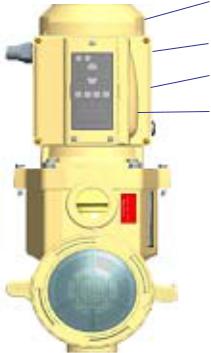
IntelliFlo VS-3050 Motor Assembly
The IntelliFlo three-phase six-pole motor operates at 3450 RPM (at 92% efficiency) and 1000 RPM (at 90%). The drive assembly is continually cooled by an external fan. Dual seals on the motor shaft and at the fan assembly seal the entire motor from any moisture from entering the motor assembly. For added protection, a slinger located in front of the main shaft seal assists in slinging water away from the shaft opening in the flange.
Motor fan cover
Motor assembly
Drive assembly and electronics enclosure
Control panel cover
 Communication port for connection to EasyTouch, IntelliTouch or SunTouch control system or IntelliComm communicaton center via twowire RS-485 cable
IntelliFlo VS-3050 Motor Assembly
IntelliFlo VS-3050 Installation and User’s Guide
3
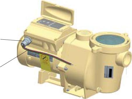
IntelliFlo VS-3050 Drive Assembly and Control Panel
The IntelliFlo drive assembly consists of an operator control panel and the system electronics that drive the motor. The drive microprocessor controls the motor by changing the frequency of the current it receives together with changing the voltage to control the rotational speed.
Operator Control Panel,
buttons and LEDs 
¾” NPT male threaded PVC nipple
Three Wire Harness Red (hot), Red (hot), Green (Ground)
+/- 20% of 230 Volt
IntelliFlo VS-3050 Drive Assembly
IntelliFlo VS-3050 Motor Features
•Permanent Magnet Synchronous Motor (PMSM)
•High efficiency (3450 RPM 92% and 1000 RPM 90%)
•Superior speed control
•Operates at lower temperatures due to high efficiency
•Same technology as deployed in hybrid electric vehicles
•Designed to withstand outdoor environment
•Totally enclosed fan cooled
•Three-phase motor
•56 Square Flange
•Six-Pole
•Low noise
IntelliFlo VS-3050 Installation and User’s Guide
4
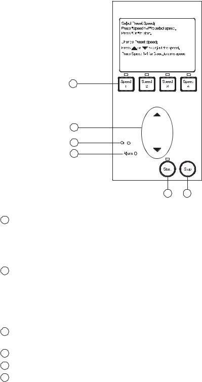
IntelliFlo VS-3050 Operator Control Panel
The IntelliFlo VS-3050 operator control panel provides manual speed controls for the pump. There are four preset speed buttons that can be selected. The Up and Down button is used to adjust the pump speed. The selected speed can be saved and assigned to one of the speed buttons.
IntelliFlo® |
|
1 |
|
2 |
|
5 |
|
6 |
|
3 |
4 |
Controls and LEDs
1 Speed 1, Speed 2, Speed 3, and Speed 4 button/LED: Press one of the speed buttons to select the desired preset pump speed. The pump preset speeds are: Speed 1 (750 RPM), Speed 2 (1500 RPM), Speed 3 (2350 RPM), and Speed 4 (3110 RPM). The speed button LED is on when the selected button is pressed. If the pump is running and the Up/Down button is used to adjust the speed, the selected speed LEDs will go off. For more about using the speed buttons, see page 5.
2 Up/Down button: While the pump is running, press the Up or Down button to increase or decrease the pump speed. To save the new pump speed, press any one of the four speed buttons for three seconds to assign the speed to the selected button (the LED be on). Four adjusted pump speeds can be assigned to the speed buttons. When the pump is using an adjusted speed and the pump is powered down, the next time the pump is powered up the pump will use the same speed. For more about using the Up/Down button, see page 5.
3 Start button/LED: Starts the pump using a selected or adjusted speed. This LED is on when the pump is running.
4 Stop button: Press this button to stop the pump.
5 On LED: This green power LED is on when IntelliFlo is powered up.
6 Alarm LED: This LED is on when an error condition occurs. This green LED will flash a certain number of times indicating a specific error condition. For the alarm LED flash sequence, refer to “Alarm and Warning LED Sequence,” on page 29.
IntelliFlo VS-3050 Installation and User’s Guide
5
Section 2
Operating IntelliFlo VS-3050
This section describes how to use the IntelliFlo VS-3050 pump control panel.
Setting the pump preset speed
IntelliFlo operates using one of the preset speeds. Use the speed buttons to select the preset speeds.
To set the pump speed
1.Ensure that the pump is powered on and the green power LED is on.
2.Press the desired speed button (1- 4) for less than three seconds to select the preset pump speed. When the selected speed button is pressed, the LED is on. The pump preset buttons and speeds are:
Speed 1 button - 750 RPM
Speed 2 button - 1500 RPM Speed 3 button - 2350 RPM
Speed 4 button - 3110 RPM
3. Press the Start button to start the pump using the selected speed if necessary.
Adjusting the pump speed
IntelliFlo can be adjusted to run at any speed between 400 RPM and 3450 RPM.
To adjust the pump speed
1.Ensure that the pump is powered on and the green power LED is on.
2.Press the Start button to start the pump if the pump is not running.
3.Press the UP/Down button to increase or decrease the pump speed.
•10 RPM increments: Press and quickly release the Up/Down button to increase or decrease the speed in 10 RPM increments.
•20 RPM increments: Press and hold the Up/Down button to continuously increase or decrease the pump speed.
4. |
Saving an adjusted speed: To save the newly adjusted pump speed, press and |
|
|
|
hold the desired speed buttons to assign the current speed. Four new pump |
|
|
|
speeds can be assigned to Speed buttons (1-4). |
Up/Down button |
|
5. |
Press the Speed button that is assigned to the adjusted speed. |
||
|
IntelliFlo VS-3050 Installation and User’s Guide
6
Starting the pump
To start the pump
1.Ensure that the pump is powered on and the green power LED is on.
2.Press the Start button (LED on) to start the pump.
Note: When the pump is using a modified speed and is powered down, the next time the pump is powered up, the pump will use that same speed.
Stopping the pump
To stop the pump
•Press the Stop button to stop the pump.
Note: The pump can automatically restart if the communication cable is connected.
Resetting the pump to factory defaults
The IntelliFlo VS-3050 pump can be reset to the factory default settings.All previously adjusted pump speeds that were saved will be erased.
To reset the pump to the factory default settings:
1.Ensure that the pump is powered on and the green power LED is on.
2.Press the Stop button to stop the pump.
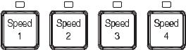
3.Press and hold all of the four Speed buttons simultaneously for four seconds. Power off the drive and reenergize. The default settings will be in effect.
Control Panel Speed Buttons
Assigning a pump address for remote control
The default communications address for the IntelliFlo is 1. This is the only IntelliFlo address that the EasyTouch and IntelliComm systems will communicate with. Therefore these devices can only communicate with one IntelliFlo. The IntelliTouch is able to communicate with four Intelliflo pumps. If more than one IntelliFlo is being used with an IntelliTouch the 2nd, 3rd and 4th pumps will have to be readdressed as described below.
To assign a pump an address:
1.Be sure that the pump is powered on and the green power LED is on.
2.Press the Stop buttons to stop the pump.
3.Press and hold both the Start and Stop buttons until the red LED will starts flashing, then press one of the four speed buttons to select which address to assign the pump.
4.Press and hold both the Start and Stop buttons to save the address. Repeat the process for the other pumps.
IntelliFlo VS-3050 Installation and User’s Guide
 Loading...