


IntelliChlor™
Electronic Chlorine Generator
(Model IC20, IC40)
Installation and User’s Guide
Patents pending
IMPORTANT SAFETY INSTRUCTIONS READ AND FOLLOW ALL INSTRUCTIONS SAVE THESE INSTRUCTIONS
© 2006 Pentair Water Pool and Spa, Inc. All rights reserved
This document is subject to change without notice
1620 Hawkins Ave., Sanford, NC 27330 • (919) 566-8000
10951 West Los Angeles Ave., Moorpark, CA 93021 • (805) 553-5000
Trademarks and disclaimers
IntelliChlor, IntelliTouch, EasyTouch and the Pentair Water Pool and Spa logo are trademarks of Pentair Water Pool and Spa, Inc. Other trademarks and trade names may be used in this document to refer to either the entities claiming the marks and names or their products. Pentair Water Pool and Spa Inc. disclaims proprietary interest in marks and names of others.
P/N 520589 Rev D - 04/28/2006

i
Contents |
|
IntelliChlor Overview .................................................................................................................................... |
1 |
Features ...................................................................................................................................................... |
1 |
IntelliChlor models ....................................................................................................................................... |
2 |
Electrolytic Cell Controller............................................................................................................................ |
3 |
IntelliChlor Power Center .............................................................................................................................. |
3 |
System Diagram .......................................................................................................................................... |
3 |
Loop Plumbing Diagram ............................................................................................................................... |
4 |
IntelliChlor Plumbing Diagram ...................................................................................................................... |
4 |
Section 1: IntelliChlor Control Panel ......................................................................................... |
5 |
Salt Level Status LEDs ............................................................................................................................... |
5 |
Status LEDs ................................................................................................................................................ |
5 |
Sanitizer Output LED Indicators .................................................................................................................. |
6 |
More and Less Output Buttons .................................................................................................................... |
6 |
Self Cleaning (reverse) ................................................................................................................................ |
6 |
Section 2: Operating IntelliChlor ............................................................................................... |
7 |
Initial Startup Period .................................................................................................................................... |
7 |
Operation ..................................................................................................................................................... |
7 |
Startup Procedure (Super Chlorination) ........................................................................................................ |
8 |
Apply power ................................................................................................................................................. |
8 |
Operating in winter ....................................................................................................................................... |
8 |
Recommendations ....................................................................................................................................... |
8 |
General Cautions ......................................................................................................................................... |
8 |
Section 3: User Maintenance...................................................................................................... |
9 |
Daily service................................................................................................................................................ |
9 |
Weekly service. ........................................................................................................................................... |
9 |
Monthly Service........................................................................................................................................... |
9 |
Cell Usage Hours Meter ............................................................................................................................. |
10 |
Electrolytic Cell Cleaning ........................................................................................................................... |
10 |
Winterizing ................................................................................................................................................. |
11 |
Chemistry You Need to Know ..................................................................................................................... |
11 |
Optimum Pool Water Conditions ................................................................................................................. |
12 |
Chlorine Testing ......................................................................................................................................... |
13 |
What Type of Salt to Use ........................................................................................................................... |
13 |
How Much Salt to Use? ............................................................................................................................. |
13 |
How to Add Salt to the Pool ....................................................................................................................... |
14 |
Pool Water Preparation ............................................................................................................................... |
16 |
Determining Pool Size (m3 of Water in Your Pool) ....................................................................................... |
16 |
Determining Pool Size (Gallons of Water inYour Pool) ................................................................................ |
16 |
IntelliChlor Pass-Through Cell .................................................................................................................... |
16 |
Selecting Model Size ................................................................................................................................. |
16 |
Section 4: Installation ............................................................................................................... |
17 |
Kit Contents .............................................................................................................................................. |
17 |
Required Tools ........................................................................................................................................... |
17 |
Installing the Cell Assembly ...................................................................................................................... |
18 |
Connecting the Cell Power Cable to the Power Center ............................................................................... |
18 |
Connecting IntelliChlor to an IntelliTouch System ...................................................................................... |
19 |
Connecting IntelliChlor to an EasyTouch System ....................................................................................... |
21 |
Section 5: Troubleshooting ...................................................................................................... |
22 |
Table 1:Troubleshooting IntelliChlor ............................................................................................................ |
22 |
Table 2:Troubleshooting the Power Center ................................................................................................. |
23 |
Electrical Specifications and 110 VAC and 220 VAC Wiring ....................................................................... |
24 |
IntelliChlor Installation and User’s Guide
ii
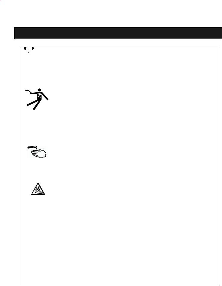
IMPORTANT SAFETY PRECAUTIONS
SAVE THESE INSTRUCTIONS


 Important Notice: Attention Installer: This manual contains important information
about the installation, operation and safe use of this product. This information should be given to the owner and/or operator of this equipment. When installing and using this electrical equipment, basic safety precautions should always be followed, including the following:
 WARNING: IMPORTANT SAFETY INSTRUCTIONS PERTAINING TO A
RISK OF FIRE, ELECTRIC SHOCK, OR INJURY TO PERSONS READ. AND FOLLOW ALL INSTRUCTIONS.
Before installing this product, read and follow all warning notices and instructions which are included. Failure to follow safety warnings and instructions can result in severe injury, death, or property damage. Call (800) 831-7133 for additional free copies of these instructions.
 WARNING: To reduce the risk of injury, do not permit children to use this product unless they are closely supervised at all times.
 WARNING: When mixing acid with water, ALWAYS ADD ACID TO WATER. NEVER ADD
WATER TO ACID.
 WARNING: To reduce the risk of injury, service should only be attempted by a qualified Pool Service Professional.
 WARNING: Do not operate electrolytic cell without proper flow or water circulation. A build-up of flammable gases will result in hazardous conditions.
 CAUTION - This chlorinator is for use with permanently-installed pools and may also be used with hot tubs and spas if so marked. Do not use with storable pools.
A permanently-installed pool is constructed in or on the ground or in a building such that it cannot be readily disassembled for storage. A storable pool is constructed so that it is capable of being readily disassembled for storage and reassembled to its original integrity.
 CAUTION - When using IntelliChlor with an IntelliTouch system, it is recommended to wire the IntelliChlor Power Center to the pump side of the relay located in the IntelliTouch Load Center. This
wiring method does not require a ground fault circuit-interrupter (GFCI) to protect the circuit. A green colored terminal (or a wire connector marked “G”, “GR”, “Ground” or “Grounding”) is provided within the terminal compartment in the Power Center transformer enclosure. To reduce risk of electric shock, connect this terminal or connector to the grounding terminal of your electric service or supply panel with a conductor equivalent in size to the circuit conductors supplying this equipment. The power supply must be interconnected with pool pump motor power source. This insures the IntelliChlor chlorinator and pool pump will switch on and off together.
IntelliChlor Installation and User’s Guide

iii
IMPORTANT SAFETY PRECAUTIONS
SAVE THESE INSTRUCTIONS
 CAUTION - Use of chemicals other than those recommended may be hazardous. Follow the Chemical Manufacturer’s Instructions.
 CAUTION - To reduce the risk of electric shock, install IntelliChlor cell at least 5 feet from the inside wall of the pool.
 CAUTION - Install the IntelliChlor unit a minimum of two (2) feet from the heater outlet.
 CAUTION - It is recommended to install a Pentair 2” CHECK VALVE (P/N 263042) between the input side of the IntelliChlor cell and the main heater output pipe.
 CAUTION - A solid copper, bonding conductor not smaller than No. 8 AWG (8.4 mm) should be connected from the accessible wire connector on the unit to all metal
parts of the swimming pool, spa, or hot tub structure and to all electrical equipment, metal conduit, and metal piping within 5 feet (1.5 m) of the inside walls of a swimming pool, spa, or hot tub, when the unit is installed within 5 feet of the inside walls of the swimming pool, spa, or hot tub.
Canada - Industry Canada (IC) - This device complies with RSS210 of Industry Canada. (1999)
FCC Standard - 47 CFR Part 15, Subpart C (Section 15.247). This version is limited to chapter 1 to chapter 11 by specified firmware controlled in the U.S.A.
Federal Communications Commission (FCC) - This device complies with Part 15 of the FCC Rules. Operation is subject to the following two conditions: (1) this device may not cause interference, and (2) this device must accept any interference, including interference that may cause undesired operation of the device.
Interference Statement - This equipment has been tested and found to comply with the limits for a Class B digital device, pursuant to Part 15 of the FCC Rules. These limits are designed to provide reasonable protection against harmful interference in a residential installation. This equipment generates, uses and can radiate radio frequency energy and, if not installed and used in accordance with the instructions, may cause harmful interference to radio communications. However, there is no guarantee that interference will not occur in a particular installation. If this equipment does cause harmful interference to radio or television reception, which can be determined by turning the equipment off and on, the user is encouraged to try to correct the interference by one or more of the following measures:
•Reorient or relocate the receiving antenna.
•Increase the separation between the equipment and receiver.
•Connect the equipment into an outlet on a circuit different from that to which the receiver is connected.
•Consult the dealer or an experienced radio/TV technician for help.
Note: Modifications not expressly approved by the party responsible for FCC compliance could void the user’s authority to operate the device.
IntelliChlor Installation and User’s Guide

iv
Declaration of Conformity
We declare, under our sole responsibility, that the product identified in this declaration, and to which this declaration relates, are in conformity with the protection requirements of Council Directive 89/ 336/EEC and standards IP33
•Standard EN60335-1:2001, EN60529
•Standard EN6100-3-2:2000, EN6100-3-3:1995 +A1:2001
•Standard EN 55014-2: 1997 +A1:2001, EN 55014-1 2000 +A1, +A2 2002
Manufacturer: |
Pentair Water Pool and Spa, Inc. |
|
1620 Hawkins Ave, Sanford, NC 27330 |
|
10951 West Los Angeles Ave, Moorpark, CA 93021 |
Installation Steps Summary
The recommended IntelliChlor installation steps are:
1Review ChemistryYou Need to Know (page 11): Review this important information.
2Review Optimum PoolWater Conditions (page 12): Review NSPI standards information.
3Review PoolWater Preparation (page 16): Review this important information.
4Installing the cell into the plumbing system - Connecting the cell to the Power Center (page 17 - 21): Installing the cell into the pool plumbing system. Cabling the cell to the Power Center and connecting IntelliChlor to an IntelliTouch or EasyTouch system.
5Operating and Maintaining IntelliChlor (page 7 and 9): Operating and maintenance information for IntelliChlor.
Technical Support
Contact Technical Support at:
Sanford, North Carolina (8 A.M. to 5 P.M.)
Phone: (800) 831-7133
Fax: (919) 566-8920
Moorpark, California (8 A.M. to 5 P.M.)
Phone: (800) 831-7133
Fax: (805) 530-0194
Web sites
visit www.pentairpool.com and www.staritepool.com
IntelliChlor Installation and User’s Guide
1
IntelliChlor Overview
The IntelliChlor™ salt chlorinator uses a process known as electrolysis to produce Sodium Hypochlorite (liquid chlorine) from a low concentration of salt added to the pool water. Hypochlorite kills bacteria, oxidizes organic material, and kills algae, then reverts back to salt. IntelliChlor then reuses the salt and the process starts over again. The IntelliChlor system is comprised of the Power Center and Electrolytic Cell.
Features
•Superior design combines cell and control panel as one assembly.
•Cell blades are made from a titanium metal base and coated with precious metal Ruthenium oxide.
•Cell blades are capable of lasting in excess of 10,000 hours.
•The cell assembly can be installed horizontally or vertically.
•Separate Power Center mounts to wall at equipment pad, for easy AC wiring.
•Easily serviced.
•Electronics run cool for long, reliable life.
•Cell hours meter reports current usage to determine how many hours remain.
•IC40 model produces up to 1.40 lbs. of chlorine per day. The IC20 model produces .70 lbs per day.
•Salt level bar graph shows the amount of salt in pool.
•Red and green LED indicators show system status for power, water flow, and cell status.
•MORE and LESS output buttons control how much chlorine is produced.
•BOOST cycle sets the unit to maximum chlorine output for 24 hours.
•Cell lifetime is tracked with at-a-glance green LED indicators.
•UL listed to UL1081 standards for swimming pool chlorinators.
IntelliChlor models
The IntelliChlor salt chlorinator system models are:
•PC 100 (P/N 520556): Power Center Kit.
•IC 20 Cell (P/N 520554): Designed for pools up to 20,000 U.S. gallons (75 liters), this cell will produce approximately 0.70 pounds of chlorine per 24 hour period. This cell uses two terminal blades and five bi-polar blades making this system more cost competitive.
•IC 40 Cell (P/N 520555): Designed for pools up to 40,000 U.S. gallons (151 liters), the cell will produce approximately 1.40 pounds of chlorine per 24 hour period. This cell uses three terminal blades and ten bi-polar blades, five on each side of the center terminal blade. This will supply more than enough chlorine for almost any residential and many smaller commercial pools.
•IntelliChlor pass-through cell (P/N 520588): For new pool start-up.
IntelliChlor Installation and User’s Guide
2
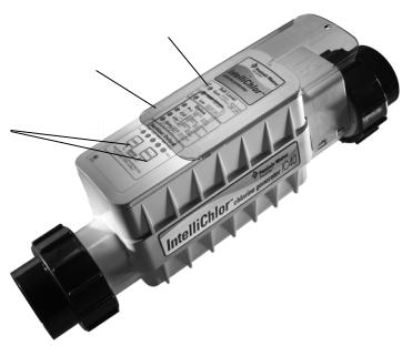
Electrolytic Cell Controller
The electrolytic cell controller includes a control panel with buttons and LED indicators to fully control and produce chlorine. The cell controller measures the water temperature and salt level to optimally produce chlorine. If the salt level is too low (red on salt display), the cell is turned off until salt is added to the pool. The controller has a self-cleaning cycle which reverses the cell polarity, reducing calcium buildup. This feature turns the cell on and off at regular intervals to prevent calcium and scale buildup and further maximizes cell life.
The electrolytic cell contains the control electronics and bipolar electrodes that perform the electrolysis and produce chlorine when energized with DC current. Chlorine is generated as pool water containing salt passes through the cell. The chlorine production can be varied by either adjusting the sanitizer output level on the cell or by varying the number of hours IntelliChlor is on each day. IntelliChlor automatically cleans the Cell electrodes once every few hours. This does not interrupt the production of Chlorine. The cell also contains a mechanical flow sensor to ensure the proper amount of water is passing through the cell to allow chlorination to occur. The cell automatically measures the water salinity and temperature and displays on the top of the cell using lights. The cell includes a 15 ft. UL approved four conductor 16 gauge cable for connection to the Power Center.
•Flow Sensor: A cell flow sensor assures that there will always be adequate water flow through the cell no matter how it is plumbed.
•Temperature Sensor: To protect the unit from operation and potential damage, when the temperature of the water falls below 52° F, the temperature sensor switches the unit off.
•Salt Sensor: Two salt sensor probes extend into the cell chamber and are activated upon start up of the system and/or every eight hours of running. Upon start-up, the salt sensor flashes for two minutes to indicate it is in analysis mode, then determines the salt level and displays it.
Control Panel status LEDs
Clear sliding cover
MORE and LESS output buttons
IntelliChlor Cell Assembly
IntelliChlor Installation and User’s Guide

3
IntelliChlor Power Center
The Power Center converts AC electrical current to a low voltage DC current which is required by the cell to perform the electrolysis. The power supply is connected with the pool circulation pump electrical source so that the electrolytic cell only operates when the pool pump is on. The enclosure can be mounted vertically on the wall up to 15 feet away from the cell controller. The Power Center contains the transformer, fuse, connector to the cell and the 110 VAC and 220 VAC wiring configuration with the 36 VDC output cable to the cell controller. A fuse holder is mounted on the bottom of this enclosure for additional protection. There are no other controls or lights on the unit. For more information about the Power Center, see the “IntelliChlor Power Center Installation Guide,” (P/N 520590).
IMPORTANT: Before plugging or unplugging the IntelliChlor cell to the Power Center, first switch off the AC power to the Power Center, either by switching off the filter pump or setting the associated circuit breaker to OFF.
Power Center (Model PC 100)
System Diagram
The following diagram shows the IntelliChlor system functionality. It is recommended to install a two inch check valve between the input side of the IntelliChlor cell and the main heater output pipe.
Pool pump and |
Power Center |
Pentair two inch Check |
|
Power Center MUST |
|||
|
Valve (recommended) |
||
be wired to switch |
|
||
|
(P/N 263042) |
||
on and switch off |
|
||
|
|
||
together |
|
|
IntelliChlor Installation and User’s Guide
4
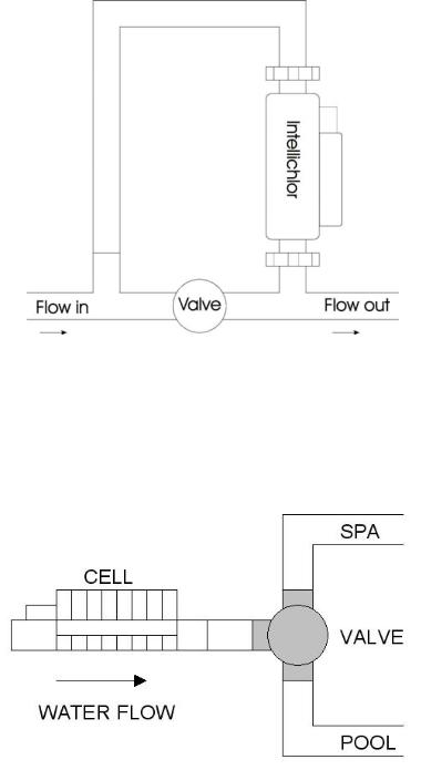
Loop Plumbing Diagram
The IntelliChlor will operate in water flow rates from 15 gallons per minute up to 110 gallons per minute (the limit of 2” plumbing). For flow rates over 80 gallons per minute, it is recommend that you use a bypass loop (shown below) for best chlorine production. Installations with flow rates over 80 gallons per minute are those that have in-floor cleaning systems or boost pumps. These systems should use a bypass loop with the IntelliChlor.
IntelliChlor Plumbing Diagram
Plumb the IntelliChlor cell AFTER the filter and heater. If installed on a pool/spa combination system, the plumb the IntelliChlor cell BEFORE the pool/spa return valve to allow proper chlorination of both the pool and spa. See diagram below.
IntelliChlor Installation and User’s Guide
 Loading...