


Automatic Pool Cleaner
Installation and
User’s Guide
IMPORTANT SAFETYINSTRUCTIONS
READ AND FOLLOW ALL INSTRUCTIONS
SAVE THESE INSTRUCTIONS
Technical Support
Sanford, North Carolina (8 A.M. to 5 P.M.)
Moorpark, California (8 A.M. to 5 P.M.)
Phone: (800) 831-7133
Fax: (800) 284-4151
Web sites: visit www.pentairpool.com and staritepool.com
Protected by one or more of the following U.S. Patents and all corresponding foreign counterparts: U.S. Pat No 5,293,659, 5,303,444, 5,371,910, 5,386,607, 5,469,596, 5,664,275, 5,799,351, and 5,974,647
© 2007 Pentair Water Pool and Spa, Inc. All rights reserved
This document is subject to change without notice
1620 Hawkins Ave., Sanford, NC 27330 • (919) 566-8000
10951 West Los Angeles Ave., Moorpark, CA 93021 • (805) 553-5000
Trademarks and Disclaimers:
Great White® and Pentair Water Pool and Spa® are registered trademarks of Pentair Water Pool and Spa, Inc. and/or its affiliated companies in the United States and/or other counties. Unless noted, names and brands of others that may be used in this document are not used to indicate an affiliation or endorsement between the proprietors of these names and brands and Pentair Water Pool and Spa, Inc. Those names and brands may be the trademarks or registered trademarks of those parties or others.
PN789 (Rev B) - December 7, 2007

i
Contents |
|
Important Safety Precautions .............................................................................. |
ii |
Section 1: Overview ............................................................................................ |
1 |
Preparation of your pool ............................................................................... |
2 |
Cleaner assembly ............................................................................ |
2 |
Hose Assembly ................................................................................ |
3 |
Section 2: Installation .......................................................................................... |
5 |
Standard Installation..................................................................................... |
5 |
Optional Installation...................................................................................... |
8 |
Section 3: Operation ............................................................................................ |
11 |
Cleaner Operation and Movement ............................................................... |
11 |
Clicking sound ................................................................................ |
11 |
Movement around the pool ............................................................... |
11 |
Picks up “big stuff” ....................................................................................... |
11 |
Fine-tuning valves and connections ............................................................ |
12 |
Valves (pump, skimmer, and main drain) and vacuum adjustments 12 |
|
Too much vacuum? ......................................................................... |
12 |
Not enough vacuum? ....................................................................... |
12 |
In-Line leaf canisters ........................................................................ |
13 |
Skimmer connection ........................................................................ |
13 |
Skimmer vac plates ......................................................................... |
13 |
Skimmer vac plate vacuum control adjusters .................................. |
13 |
Section 4: User Maintenance ............................................................................. |
15 |
Hose Storage ............................................................................................... |
15 |
Disassembly ................................................................................................ |
16 |
Reassembly ................................................................................................ |
17 |
Illustrated Parts List ..................................................................................... |
18 |
Section 5: Troubleshooting ................................................................................ |
19 |
Great White Installation and User’s Guide
ii
IMPORTANT SAFETY PRECAUTIONS


 Important Notice:
Attention Installer: This manual contains important information about the installation, operation and safe use of this product. This information should be given to the owner and/or operator of this equipment.
WARNING — Before installing this product, read and follow all warning notices and instructions which are included. Failure to follow safety warnings and instructions can result in severe injury,
death, or property damage. Call (800) 831-7133 for additional free copies of these instructions.
WARNING — Hazardous suction. Can trap and tear hair or body parts. Can cause drowning.
Do not play with cleaner or hose or apply to body. Do not let children use or play with pool cleaner. Stop pump before attempting to clean unit.
CAUTION — Oscillator may injure hands or fingers. Stop pump before attempting to clean out pool cleaner head.
1058 0594
WARNING — Hose can trip or entangle swimmers. Do not allow swimmers in pool while pool cleaner is operating.
General Installation Information
Pre-installation check list
Before installing the cleaner in a vinyl liner pool:
Check liner closely for signs of deterioration or damage from age, chemicals, pool wall damage, etc. If any damage is found, have a qualified pool professional make all necessary repairs. Also, if there are stones, roots, etc., under the liner, remove them before installing the cleaner.
Before installing the cleaner in a gunite pool or a pool that is partially or completely tiled:
Repair loose tiles and tighten any loose light rings.
Before installing the cleaner, clean your filter system:
Make sure you have cleaned the filter, including backwashing, rinsing, and emptying all baskets. A clean system is necessary for proper cleaner operation and coverage.
Great White Installation and User’s Guide

iii
IMPORTANT SAFETY PRECAUTIONS (continued)
General Installation Information (continued)
Before installing the cleaner, fill the hose with water:
Always make sure the cleaner head is submerged and the hose is full of water before connecting the hose to the filtration system (whether through a skimmer or dedicated wall fitting). Air in the system can damage the pump through dry running and overheating.
Before installing the cleaner, understand cleaner coverage:
The cleaner is designed to rid your pool of debris in approximately 4-6 hours. Less time could be needed, depending on the pool size.
The cleaner was not designed to automatically clean steps or swimouts or to work under a solar cover. It was also not designed to do initial cleanup for a new pool or when opening your pool for the season.
WARNING — Suction entrapment, injury, and drowning hazard. If your pool has a dedicated suction port (“vac port”) for vacuuming or for an automatic pool cleaner, it must be covered when not in use.
A spring loaded safety cover is included with your cleaner. Install it on the suction port to prevent entrapment and injury.
Great White Installation and User’s Guide
iv
Blank Page
Great White Installation and User’s Guide
1
Section 1
Overview
Great White Automatic Inground Pool Cleaner
Congratulations on your purchase of the world’s best pool cleaner! Nothing quite compares to the Great White’s ability to make dirt disappear. With its 15” cleaning path and unique bristle drive, your Great White automatic, inground pool cleaner will deliver fast, complete coverage of your pool.
Great White Automatic Inground Pool Cleaner
Model GW9500
Great White Installation and User’s Guide
2
Preparation of your pool
Before you assemble and install your Great White automatic pool cleaner, you should make sure that your pool is clean and free of algae. If necessary, make the following preparations before proceeding.
• Chemically balance the pool water
• Brush the pool and let the debris settle
• Hand vacuum the pool thoroughly
• Clean the filter and pump strainer basket (Figure 1)
Cleaner assembly |
|
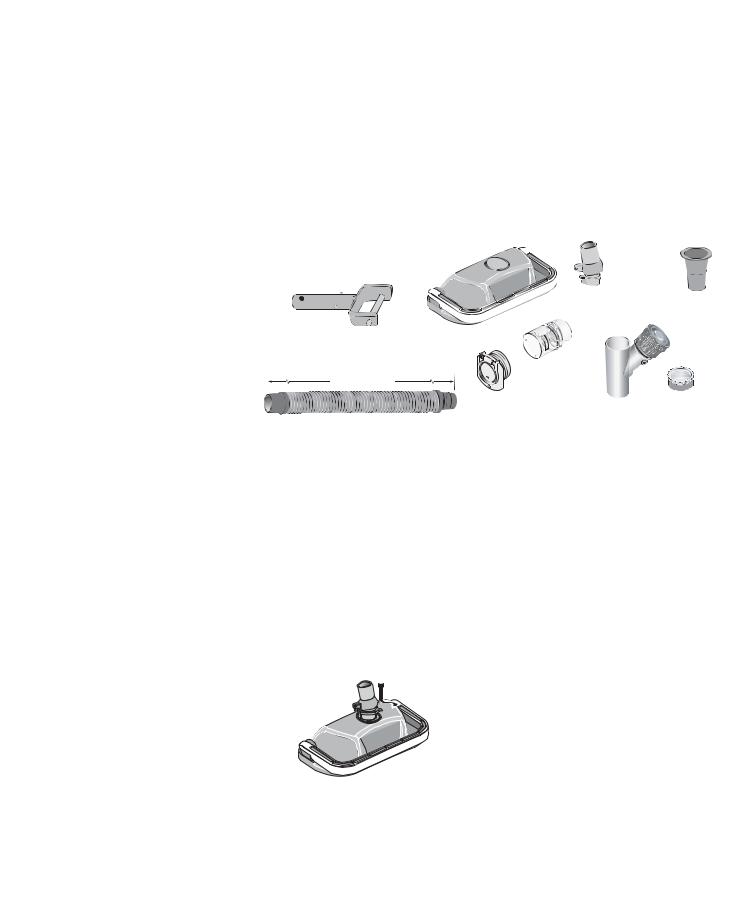
1. Check parts |
Figure 1 |
Remove Great White and all of its parts from the box and check to make sure that all components were included (Figure 2).
Cleaner
SwivelAssembly
HandleAdapter
Reducer Cone
Hose: Twelve 4’lengths
Vacuum Regulator
Regulator Cap
Vacuum Port Fitting
Flow Gauge
Cleaner |
|
|
|
Handle Adapter |
|
|
|
|
|
Swivel |
Reducer |
|
|
Ass'y |
Cone |
|
W |
|
|
|
W |
|
|
|
O |
|
|
|
L |
|
|
|
F |
|
|
|
M |
|
|
|
U |
|
|
|
M |
|
|
|
I |
|
|
Hose |
N |
|
|
IM |
|
|
|
Flow |
|
|
|
Twelve |
|
|
|
4’ lengths |
Gauge |
|
|
Vacuum |
|
Vacuum |
Regulator |
Port Fitting |
Regulator |
Cap |
|
Figure 2 |
|
|
|
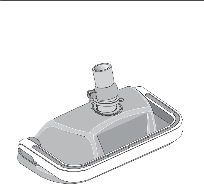
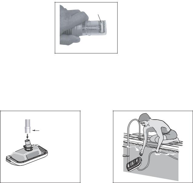
2.Attaching swivel assembly to cleaner head
Installing the swivel assembly is a snap. Just insert it into the cleaner body and give it a quarter turn (Figure 3). If you attach a unidapt handle to the swivel for manual vacuuming, be sure it is the special, floating unidapt handle provided with the cleaner (Replacement Part No. GW9019). Use of a different unidapt handle will hinder the cleaner’s performance.
Swivel
Assembly 
Figure 3
Great White Installation and User’s Guide
3
Hose Assembly
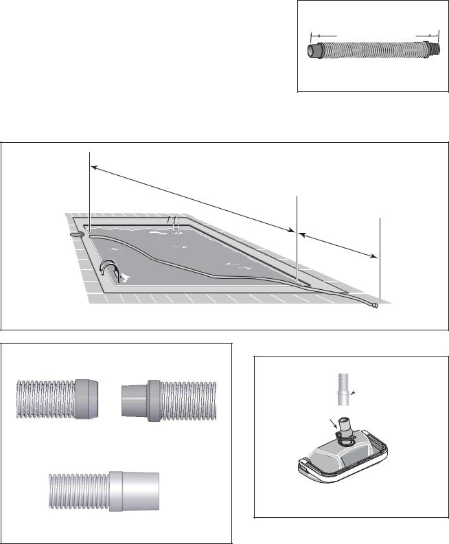
Assemble the hose
The unit includes twelve sections of hose, each 4 feet (4’) in length (Figure 4). Do not cut the
hose lengths. You will need to connect these 4’sections of hose to create a combined hose length that is at least 4’ longer than the distance from your suction source (whether
skimmer or dedicated suction line) to the farthest point in the pool (Figure 5). Connect the hoses by twisting and pushing the female ends onto the male ends after wetting the ends in the pool (Figure 6). A special “leader” hose section is designed to connect to the cleaner’s swivel assembly and therefore has a larger hose cuff than the other hose lengths (Figures 7 and 8). Failure to use this leader hose section to attach the hose to the cleaner’s swivel assembly will hinder your cleaner’s performance. If additional hose is needed,
use only hoses from your Pentair Water Pool and Spa dealer (order replacement part No. 41200-0131). Use of another manufacturer’s hose will hinder cleaner coverage.
Hose |
|
|
must |
|
|
equal |
|
|
longest |
|
|
stretch |
|
|
— |
|
|
— |
plus |
|
|
at |
|
|
least 4 |
feet. |
|
|
Figure 5
Female hose end |
Male hose end |
 Leader Hose
Swivel
Assembly 
Figure 6
Leader Hose
Connect to Swivel Assembly
Figure 8
Figure 7
Great White Installation and User’s Guide
4
Blank Page
Great White Installation and User’s Guide
5
Section 2
Installation
This section describes how to install the Great White pool cleaner. Great White is designed to work in a wide variety of swimming pools. Both the standard in-skimmer installation and optional vac port installation are covered below. If your pool configuration is unlike any of the examples, contact your Pentair Water Pool and Spa dealer for assistance, or call our toll-free Customer Helpline at 1-800-831-7133.
Standard Installation
For pools with one skimmer, using the vacuum regulator
The manufacturer recommends the Standard Installation through the pool’s skimmer (Figure 8) The advantage of this installation is its use of the vacuum regulator (Figure 9) to balance the water flow between the skimmer and the Great White pool cleaner. The vacuum regulator can be adjusted to changes in the amount of water flow to provide Great White with the power necessary to ensure proper cleaning performance, and the manufacturer strongly recommends its use for maximum safety and performance.
Skimmer |
Vacuum |
|
Regulator |
|
Adjustment |
|
Knob |
Figure 8 |
Figure 9 |
1.Turn the pool pump off
2.Adjust valves for vacuuming
Adjust the pump valves (if your system has valves) to direct all suction to the skimmer. Close the main drain and all suction lines, except the line from the skimmer to which Great White will be connected.
3.Remove the skimmer basket from the skimmer
4.Install vacuum regulator

 WARNING! Hazardous suction. Can cause entrapment with severe personal injury or drowning.
Use the vacuum regulator in conjunction with your pool cleaner system at all times. The vacuum regulator has an adjustment knob (Figure 9). If suction is too high, the knob is turned counterclockwise to decrease the suction. If the suction is too low, the knob is turned clockwise to increase the suction.
Great White Installation and User’s Guide
6
Standard Installation (Continued)
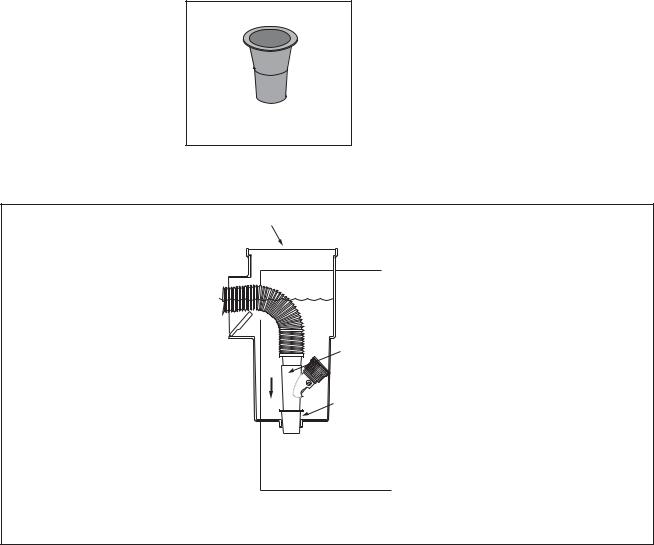
The vacuum regulator must be installed in conjunction with the reducer cone (Figure 10). The reducer cone is required to make most skimmer connections. It will keep the hose and vacuum regulator in place once the filter system is stopped.
Figure 10
To install the vacuum regulator, insert the vacuum regulator and reducer cone in the skimmer. Attach the end of the hose to the regulator (Figure 11).
Skimmer
Vacuum
Regulator
Reducer Cone
 To Pump
Figure 11: Vacuum regulator installed in the skimmer with the hose attached
Make sure the vacuum regulator is submerged at all times. If not, the pump will suck air through the vacuum regulator and lose prime. This could damage the pump.
Great White Installation and User’s Guide
7
Standard Installation (Continued)
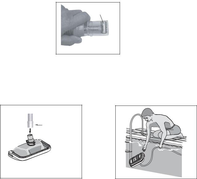
5.Check Flow
With the main drain closed, and one end of the hose attached to the regulator installed in the skimmer, insert the flow gauge into the other end of the hose. Keep the hose and flow gauge underwater. Turn on the pump. With the pump running, adjust the vacuum regulator (in your skimmer) until the indicator on the flow gauge is between minimum and maximum flow (Figure 12). Remove the flow gauge and proceed to step 6.
Disc Indicator
Figure 12
6.Connect Hose to the Cleaner’s Swivel Assembly
Connect the large hose cuff (Figure 13) of the leader hose to the swivel assembly on the cleaner head (Figure 13). Push the cleaner into the pool and let it sink to the bottom (Figure 14).
Large hose cuff of leader hose
designed to connect to swivel assembly (See “Hose Assembly” on Page 3)
Figure 13
Figure 14 |
7.Turn the pool pump on
After completing the installation, turn the pool pump on and allow it to run for a couple of minutes to ensure that all air cycles out of the system.
Great White Installation and User’s Guide
8
Optional Installation
Vac Port Installation with Vacuum Regulator in Skimmer
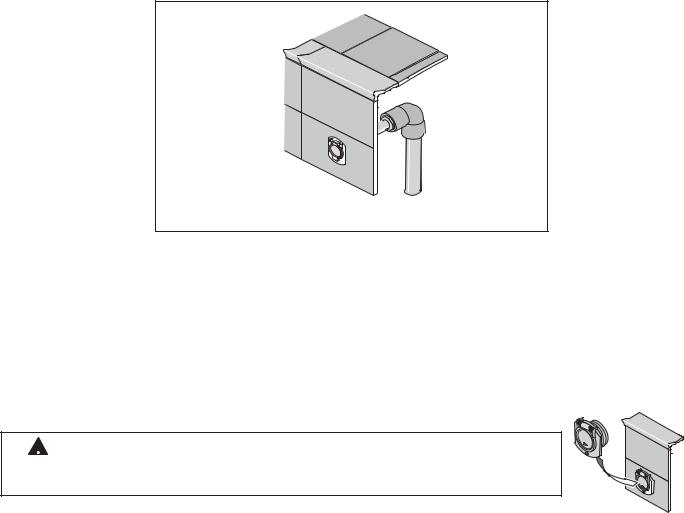
If your pool has a vac port (Figure 15), you can install Great White using the Optional Installation.
Vac Port
Figure 15
1.Turn the pool pump off
2.Adjust valves for vacuuming
Adjust the pump valves (if your system has valves) to direct all suction to the dedicated vacuum line and the skimmer. Close the main drain and all suction lines, except the line from the dedicated vacuum line to which Great White will be connected, and the skimmer where the vacuum regulator will be installed.
3.Install vac port door fitting
 WARNING! Suction entrapment, injury, and drowning hazard. If your pool has a dedicated suction port (“vac port”) for vacuuming or for an automatic pool cleaner, it must be covered when not in use.
A spring loaded safety cover (the “vac port fitting”) is included with this pool cleaner |
Figure 16 |
|
(Figure 16). Install it on the dedicated vacuum line to prevent entrapment and injury. For |
||
|
||
details please refer to the Vac Port Instruction sheet included with your vac port fitting. |
|
|
To install the included vac port fitting: |
|
1.Screw the vac port fitting into the dedicated vacuum line opening.
2.Orient the vac port fitting so the arrow on the door points up.
3.Secure the cover by tightening the allen-screw below the door, into the dedicated vacuumlinefitting.
4.Remove the skimmer basket from the skimmer
Great White Installation and User’s Guide
9
Optional Installation (continued)
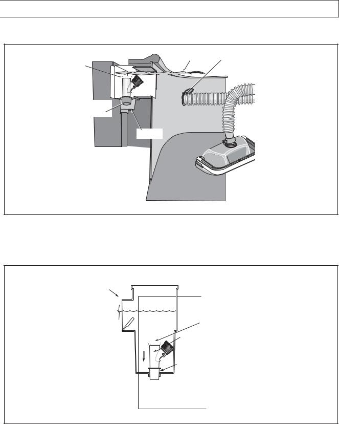
5. Install vacuum regulator

 WARNING! Hazardous suction. Can cause entrapment with severe personal injury or drowning.
To install the vacuum regulator, insert the vacuum regulator and reducer cone in the skimmer (Figure 17).
Water |
Attach hose to |
Level |
vac port |
Vacuum |
|
Regulator |
|
with Regulator |
|
Cap attached |
|
Reducer
Cone
Skimmer
Gate valve for vacuum port must be fully open
1900 0405
Figure 17: Vacuum regulator and reducer cone inserted in skimmer
To prevent water from flowing through the top of the vacuum regulator, attach the regulator cap to the vacuum regulator (Figure 18). Attach the end of the hose to the vac port fitting installed in the dedicated vacuum line (Figure 17).
Skimmer
Regulator Cap
Vacuum
Regulator
Reducer Cone
 To Pump
Figure 18: Vacuum regulator installed in the skimmer with the regulator cap attached
Great White Installation and User’s Guide
10
Optional Installation (Continued)
6.Check Flow
With the main drain closed, and one end of the hose attached to the vac port fitting installed in the dedicated vacuum line, insert the flow gauge into the other end of the hose. Keep the hose and flow gauge underwater. Turn on the pump. With the pump running, adjust the vacuum regulator (in your skimmer) until the indicator on the flow gauge is between minimum and maximum flow (Figure 19). Remove the flow gauge and proceed to step 7.
Disc Indicator
Figure 19
7.Connect Hose to the Cleaner’s Swivel Assembly
Connect the large hose cuff (Figure 20) of the leader hose to the swivel assembly on the cleaner head. Push the cleaner into the pool and let it sink to the bottom (Figure 21).
Large hose cuff of leader hose
designed to connect to swivel assembly (See “Hose Assembly” on Page 3)
Figure 20
Figure 21 |
8.Turn the pool pump on
After completing the installation, turn the pool pump on and allow it to run for a couple of minutes to ensure that all air cycles out of the system.
Great White Installation and User’s Guide

11
Section 3
Operation
This section contains information describing the movement and operation of your Great White Cleaner, as well as tips for “fine-tuning” your pool’s valves and connections to optimize Great White’s cleaning ability.
Cleaner Operation and Movement
Clicking sound
This is the sound of the oscillator moving back and forth in the oscillator chamber. The best speed for it is about 500 oscillations per minute. The vibration created by the oscillator moves the bristles and the cleaner. If the oscillator is running too fast, the cleaner will have a tendency to climb up the pool wall past the waterline, or “walk out of the pool” and suck air. Reduce the speed by adjusting the vacuum regulator in the skimmer.
Movement around the pool
Random motion – The cleaner will visit most spots in the pool within a six (6) hour period. It is not specifically programmed, and cannot see the dirt you are seeing. It is a random motion pattern.
The cleaner was designed to spend most of its time in the deep end, where most of the floor and wall area exists. During a six (6) hour period, the cleaner will visit the shallow end a few times.
Rotating motion – The cleaner will rise up on one side and pivot a few times per minute. This is normal and provides the following:
1.Allows leaves that are being pushed or dragged along to be sucked up into the vacuum chamber.
2.Allows the cleaner to:
Change direction Get out of corners
Get away from ladders Submerge below pool water level
Get off of domed main drain covers
Picks up “big stuff”
The cleaner will pick up some debris so large that it may jam. Simply stop the pump and remove the debris from the oscillator, or the swivel assembly.
Great White Installation and User’s Guide

12
Fine-tuning valves and connections
 WARNING! Pool pump suction is hazardous and can cause entrapment with severe personal injury or drowning. Use vacuum regulator (see instructions below) in pool cleaner system at all times.
NOTICE: Each pool’s hydraulic system and vacuum connections are different. Be sure you have installed the vacuum regulator before you “fine-tune” the system. This not only regulates vacuum, but also acts as a safety device.
WARNING! Suction entrapment, injury, and drowning hazard. If your pool has a dedicated suction port (“vac port”) for vacuuming or for an automatic pool cleaner, it must be covered when not in use.
A spring loaded safety cover (the “Vac Port Fitting”) is included with this pool cleaner. Install it on the vac port to prevent entrapment and injury. For details please refer to the Vac Port Fitting instruction sheet included with
your cleaner.
For the novice pool owner for whom pool vacuuming is a new experience, please read all of the following points, installation instructions, and trouble shooting guide carefully.
Please note the following:
•“Vacuum” and “suction” are two words meaning the same thing.
•“Dedicated suction line”, “vac port”, and “vac fitting” are different terms for a hole in the side wall of pool; this hole is connected to the pump suction and is dedicated to vacuuming.
•Some pools do not have a vac port. If your pool does have one, please read the “Suction Entrapment” warning above.
For the seasoned pool owner: The automatic pool cleaner connection and vacuum adjustments can be similar to using your manual pool vacuum. Please read on.
Valves (pump, skimmer, and main drain) and vacuum adjustments
You may need to spend some time adjusting the skimmer and main drain valves in order to obtain the best vacuum setting for good cleaner operation. Once you have found the correct valve settings for best operation, we suggest you mark the valves to ensure repeated success.
At first, set valves to give maximum vacuum to the skimmer or vac fitting you have elected to use.
Too much vacuum?
You have too much vacuum if the cleaner climbs up the pool wall past the water line to the point that the cleaner sucks air and the pump loses prime. Frequent loss of prime will damage the pump. To correct this, adjust the regulator by turning the adjustment knob counterclockwise. This will decrease the suction. If the cleaner still climbs out and sucks air, open the main drain valve slightly.
Great White Installation and User’s Guide
13
Fine-tuning valves and connections (continued)
Not enough vacuum?
You don’t have enough vacuum if the cleaner moves sluggishly or not at all. Be sure the filter system is clean and the regulator and all valves are adjusted to give you maximum vacuum. If the cleaner is still not moving, your pump may not be strong enough to operate the cleaner. Please refer to “Troubleshooting” on Page 17.
In-Line leaf canisters
If your pool is exposed to large quantities of leaves, we suggest purchasing and installing an in-line leaf canister (part no. R211084K).Aleaf canister will provide more debris-loading capacity and also provides a water by-pass when the canister is full. It is very important that the pump not starve for water!
Skimmer connection
For pools that have large quantities of “big stuff” to pick up, we suggest using the bottom of the skimmer connection in conjunction with an in-line leaf canister (part no. R211084K).Aleaf canister will provide more debris-loading capacity and also provides a water by-pass when the canister is full. It is very important that the pump not starve for water!
Skimmer vac plates
Some pool owners connect the hose to a skimmer vac plate, which allows the skimmer basket to remain in the skimmer. If this method is used, empty the basket frequently.Also make sure that the vacuum regulator provided is completely submerged so that it will not suck air and damage the pump.
Skimmer vac plate vacuum control adjusters
Some pool owners use one of a variety of manufacturer’s skimmer vac plates. Some have a vacuum control adjuster, and some do not. The adjuster could be a screw-type, a spring loaded apparatus, or a dial design. For those vac plates with adjusters, it is important to adjust them when fine tuning the vacuum for the cleaner.
Great White Installation and User’s Guide
14
Blank Page
Great White Installation and User’s Guide
15
Section 4
User Maintenance
This section describes the service and maintenance of the Great White cleaner.
 WARNING! Hazardous suction. Stop pump before attempting to clean pool cleaner.
•Keep skimmer basket and pump strainer basket clean and free of debris.
•If cleaner jams with large debris (leaves, sticks, etc.), try cleaning debris first from bottom of unit. If this doesn’t clear unit, remove top swivel assembly (turn 1/4 turn) and clear the debris from the top.
•Remove the pool cleaner from the pool before super chlorinating (shocking) or chemical balancing. Wait at least four hours after the chemical procedure before reinstalling the cleaner.
•Make sure that the cleaner’s brush bristles don’t become deformed during storage. Store the unit so that it doesn’t sit on the bristles and so that nothing compresses them.
•Do not coil the hose. Remove the hose from the cleaner when removing the cleaner from the pool. Store the hose flat and straight.
•Periodically examine bristles and vacuum skirt for wear or distortion. Replace if necessary. See "Reassembly", Page 15.
•Don't store the cleaner with the hose connected to the cleaner body or with the hose coiled. To do so will cause the hose to take a set or kink over a period of time. When reinstalled in the pool, the hose will tend to stay coiled and will cause the cleaner to malfunction.
•If the hose has taken a set, uncoil it as far as possible without damaging it and lay it out in the sun for several hours to straighten itself. Once it has relaxed and straightened out, store it laid out flat and straight (no coiling).
•Make sure the lift brush is retracted during storage. If the lift brush is down during storage and the cleaner rests on it, the brush bristles will collapse over time and the cleaner will no longer turn during operation as it was designed to do.
Hose Storage
Correct: Hose stored correctly – laid out straight, not connected to cleaner.
Wrong: Storing cleaner with hose connected will damage hose and void the hose warranty.
Great White Installation and User’s Guide
16
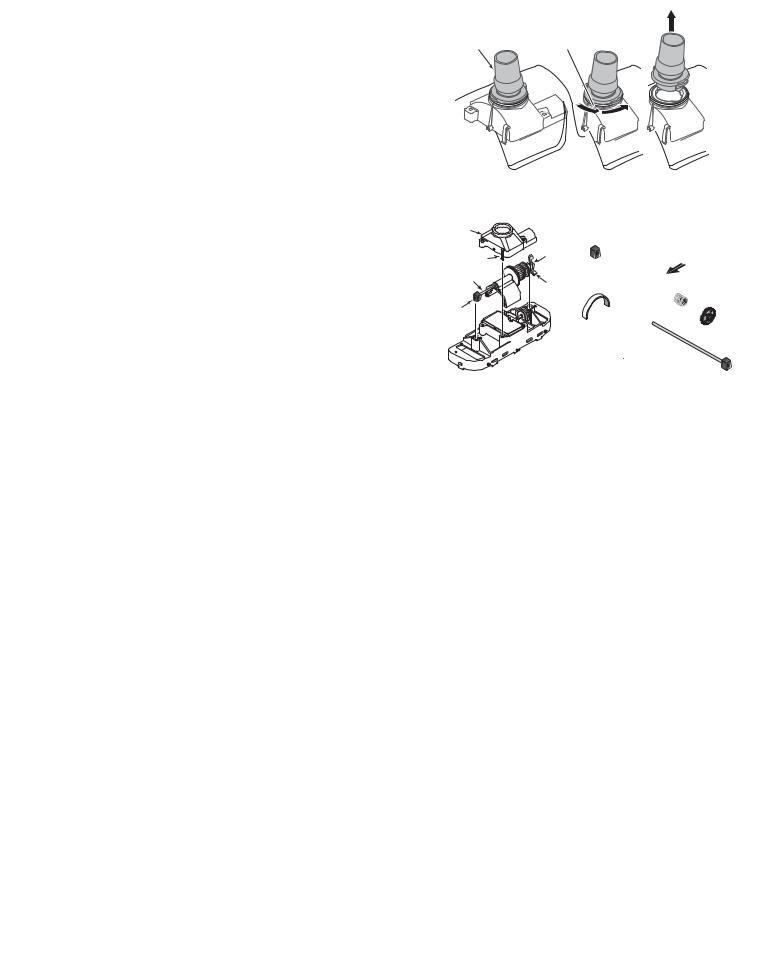
Disassembly
1. Remove swivel assembly (Figure 22) from the top of the cleaner by turning it 1/4-turn counterclockwise and pulling straight up on it.
2. Turn cleaner upside down. Remove 4 screws and remove lower body assembly from shroud.
3 . Turn lower body assembly right side up. Unsnap the 2 clips on the oscillator chamber cap (Figure 23a); lift it off.
4.Pull the long gear shaft straight up (Figure 23a) by the blocks on the ends of the shaft. Hold the seals in the oscillator and the blocks on the shaft. The cam may interfere with the shaft mounting post; if so, turn it slightly on the shaft until it clears the post. The shaft assembly can now be disassembled (Figure 23b).
5.Slide the long gear shaft out of the oscillator (with gears, complete); make sure that you don’t lose the seals out of the oscillator which may fall out at this point (Figure 23b).
5A. Oscillator seals are replaceable.
5B. Ratchet gear set and long shaft are replaceable as a unit.
6.Remove the set screw, short gear shaft, and gears (Figure 24); be sure to keep the gears on.
7.With a small screwdriver (such as a jeweler’s screwdriver), a pencil, or a pen point, depress and remove the coil spring from the lift brush mounting post (Figure 25). Replace the brush and the spring if necessary.
8.The metal ratchet tab slides out of its slot sideways; replace it by removing the center brushes and sliding in a new ratchet tab until it is flush with the edge of plastic holder (Figures 26 and 27). Replace the center brushes.
9.The brush ring pops out of the cleaner body for easy replacement.
10.If you need to replace the bumper, turn the shroud and bumper assembly upside down and remove the two screws holding the bumper to the shroud.
Swivel |
"Click" at |
assembly |
this point |
3337 1098
Figure 22 |
Locked |
Twist CCW |
Pull Straight |
|
1/4 Turn |
Up |
|
|
|
|
|
Ocillator |
|
|
|
Chamber |
|
|
|
Cap |
|
Block |
|
Clip |
|
|
|
|
|
|
|
Long Gear Shaft |
|
Cam |
|
Block |
|
|
|
|
1889 0795 |
|
|
|
|
|
1887 0795 |
Figure 23a |
|
Figure 23b |
|
|
|
1886 0795 |
Figure 24 |
Figure 25 |
|
1. Slide metal ratchet tab |
2. Slide metal ratchet tab |
|
toward end of cleaner body |
down through cleaner body |
|
|
1885 0795 |
|
1884 0795 |
Figure 26 |
Figure 27 |
Great White Installation and User’s Guide
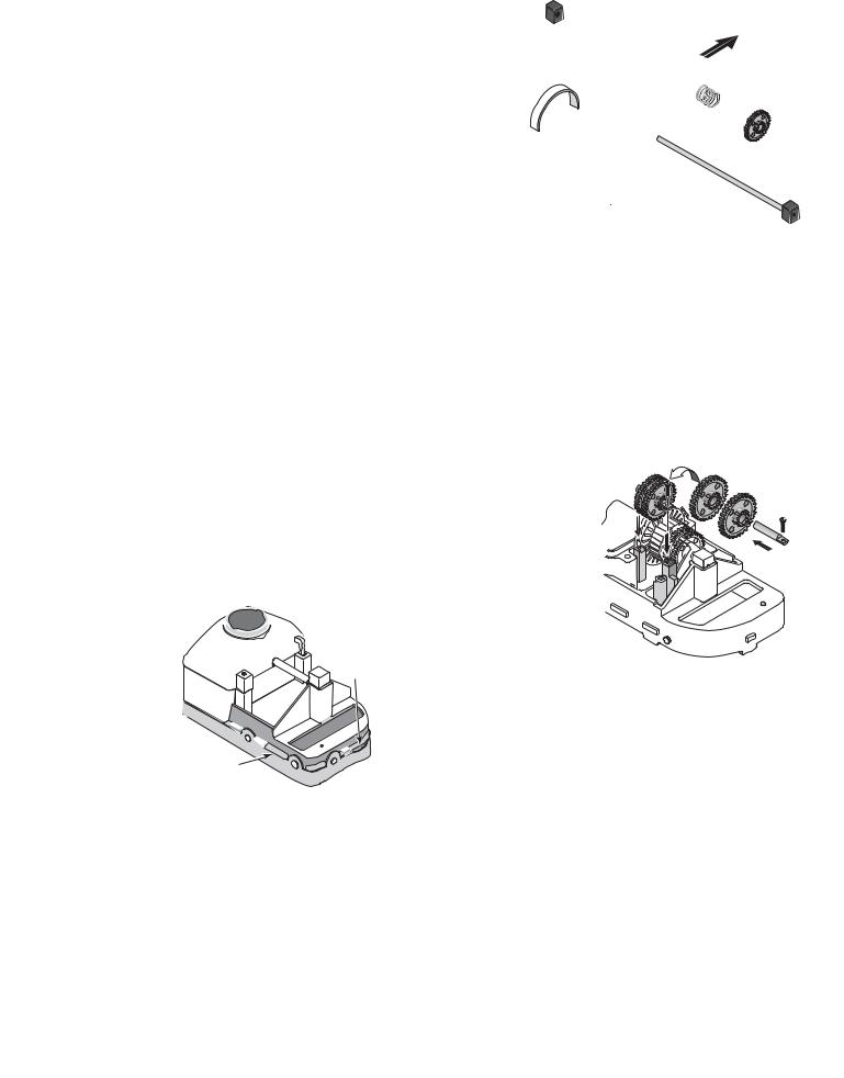
Reassembly
1. Put both white seals in the oscillator; hold them in place.
2. Install the oscillator on the long gear shaft. Install the ratchet gear on the shaft so that the teeth engage the ratchet on the oscillator. Install the spring, ratchet drum, pinion gear (large gear first), and cam (gear end first) on the shaft (See Figure 28). Hold the gears on the shaft while installing them, and compress the clutch spring to allow assembly to slip into place between the posts (See Figure 28).
3. Install the long gear shaft and end blocks in the cleaning head with the large arm of the cam down (see Figure 29).
4. Reinstall the short gear shaft, set screw and two gears (See Figure 30); the small pinion gears and the shaft set screw go on the side toward the end of the cleaner – away from the oscillator box. Make sure that the gears engage the gears on the long gear shaft.
5. Install the oscillator chamber cap and clip it in place.
6. Install the rubber vacuum skirt on the cleaner with the word ‘OUTSIDE’ showing. Start at the large pin on the back of the cleaner head (see Figure 31) and work around the cleaner. Make sure the skirt is flush against the stop strips on the cleaner head (see Figure 32).
7. Turn the cleaner over. If you removed the bumper and brush ring, replace them now.
8. Install the lower body assembly in the shroud. Fasten the cleaning head in place with 4 screws (2 long, 2 short – see Figure 33).
NOTE: Make sure that you do not dislodge the rubber vac skirt while inserting the lower body assembly past the brush ring.
17
Seals
Figure 28
Make sure Oscillator |
1894 0795 |
is partially inserted in chamber while reinstalling Shaft Assembly
 Swing Cam
Arm up for
Clearance
Oscillator 
Chamber
Figure 29
1895 0795
Not |
Figure 30 |
This |
|
This |
|
|
Figure 32 |
1892 0795 |
|
|
|
#10-16x1-3/4" Screws |
Lift Brush |
|
|
|
Location |
|
Center |
|
Center |
Start here with |
Brush |
|
Brush |
large button when |
|
installing vacuum skirt. |
||
Location |
|
Location |
|
|
|
|
'Outside' will show |
|
|
|
(facing out) when |
|
#10-16x1" Screws 1891 0795 |
|
skirt is correctly installed. |
|
|
Figure 31 |
|
Figure 33 |
Bottom View of Cleaner |
|
OUTSIDE 
1890 0795
 Rubber vacuum skirt
1893 0795
Great White Installation and User’s Guide

18
Illustrated Parts List
|
1 |
|
2 |
|
2A |
|
3 |
|
4 |
3 |
5 |
|
|
|
6 |
|
|
7 |
|
18 |
8 |
|
|
9 |
9 |
|
10 |
|
|
11 |
|
|
11A |
|
|
8 |
|
|
3 |
|
|
12 |
17 |
3 |
13 |
|
||
3 |
|
16 |
|
|
|
|
19 |
14 |
|
|
15 |
|
|
1896 0795 |
Optional Accessories
Vacpole
|
1897 0405 |
|
Key |
|
|
No. |
Description |
Part No. |
1 |
Swivel Assembly |
GW9012 |
2 |
Bumper |
GW9502 |
2A |
Bumper Insert Kit (Set of 4) |
GW9520 |
3 |
Screw Kit (4 short, 2 long) |
GW9504 |
4 |
Shroud |
GW9501 |
5 |
Brush Ring |
GW9505 |
6 |
Oscillator Chamber Cap |
GW9506 |
7 |
Cam Kit (2 & 3 Leg Cams) |
GW9507 |
8 |
Idler Gear Kit (Incl. 3 Gears) |
GW9509 |
9 |
Block Kit (Incl. 2 Blocks) |
GW9512 |
10 |
Long Gear Shaft (Stainless Steel) |
GW9513 |
11 |
Set Screw #4 Self Tapping## |
|
11A |
Shaft Kit, Stainless Steel (includes Set Screw) |
GW9536 |
12 |
Lower Body* |
GW9535 |
13 |
Lift Brush |
GW9517 |
14 |
Vacuum Skirt |
GW9508 |
15 |
Lift Brush Spring |
GW9522 |
16 |
Ratchet Tab (Stainless Steel) |
GW9523 |
17 |
Oscillator Seal Kit (Incl. 2 Seals) |
GW9004 |
18 |
Oscillator Assembly Kit (Incl. Key #17) |
|
|
(Ratchet Assembly not sold separately) |
GW9503 |
19 |
Center Brush Kit (Set of 2) |
GW9013 |
• |
Hose Kit, 12 sections, each 4 ft in length |
41200-0131 |
• |
Vacuum Regulator |
41200-0200 |
• |
Vacuum Regulator Cap |
41200-0211 |
• |
Reducer Cone |
GW9015 |
• |
Unidapt Handle |
GW9019 |
• |
Vac Port Fitting |
GW9530 |
• |
Flow gauge |
41200-0210 |
• |
Not Illustrated |
|
* |
Includes Key Nos. 6, 11A, 13, 15, 16, two idler gears and 2-arm cam |
|
##Not available separately
Great White Installation and User’s Guide
 Loading...