


 Loading...
®
PT550P Series
PT570 Series
PT573 Series
PT680-24 Series
Medium Duty Pan/Tilt
Maintenance/
Service Manual
C325SM (3/99)
U® L LISTED
Pelco • 300 W. Pontiac Way, Clovis • CA 93612-5699 USA • Pelco Online @ http://www.pelco.com In North America and Canada: Tel (800) 289-9100 or FAX (800) 289-9150 • DataFAX (800) 289-9108 International Customers: Tel (1-559) 292-1981 or FAX (1-559) 348-1120 • DataFAX (1-559) 292-0435

CONTENTS
Section |
|
|
Page |
|
1.0 |
GENERAL |
.................................................................................................. |
3 |
|
|
1.1 |
IMPORTANT SAFEGUARDS AND WARNINGS ............................... |
3 |
|
2.0 |
DESCRIPTION .......................................................................................... |
4 |
||
|
2.1 |
MODELS ............................................................................................ |
4 |
|
|
2.2 |
OPTIONS ........................................................................................... |
5 |
|
3.0 |
MAINTENANCE ......................................................................................... |
6 |
||
|
3.1 |
SERVICING .......................................DRIVE CHAIN ASSEMBLIES |
6 |
|
|
|
3.1.1 .......................................................... |
Tightening Drive Chains |
6 |
|
|
3.1.2 ........................................................... |
Chain Drive Lubrication |
6 |
|
3.2 |
RESETTING ....................................................POTENTIOMETERS |
7 |
|
4.0 |
EXPLODED .......................................................ASSEMBLY DIAGRAMS |
8 |
||
5.0 |
WIRING DIAGRAMS ................................................................................ |
22 |
||
6.0 |
WARRANTY ...........................................AND RETURN INFORMATION |
32 |
||
LIST OF ILLUSTRATIONS
Figure |
|
Page |
1 |
Servicing the Pan/Tilt ......................................................................... |
6 |
2 |
Sealant Locations .............................................................................. |
7 |
3 |
PT550P Series Exploded Assembly Diagram .................................... |
8 |
5 |
PT573 Series Exploded Assembly Diagram ..................................... |
14 |
6 |
PT680-24P and PT680-24P/PP Exploded Assembly Diagram ......... |
17 |
7 |
PT680-24SL and PT680-24SL/PP Exploded Assembly Diagram ..... |
18 |
8 |
PT550P Wiring Diagram ................................................................... |
22 |
9 |
PT550P/PP Wiring Diagram ............................................................. |
23 |
10 |
PT570P/PT570-24P Series Wiring Diagram ..................................... |
24 |
11 |
PT573 Series Wiring Schematic ....................................................... |
25 |
12 |
PT680-24P Wiring Schematic ........................................................... |
26 |
13 |
PT680-24SL Wiring Schematic ......................................................... |
27 |
14 |
PT680-24P/PP Wiring Schematic ..................................................... |
28 |
15 |
PT680-24SL/PP Wiring Schematic ................................................... |
29 |
16 |
PT680-24P/HB Wiring Schematic ..................................................... |
30 |
17 |
PT680-24SL/HB Wiring Schematic ................................................... |
31 |
LIST OF TABLES
Figure |
|
Page |
A |
PT550P Series Parts List ................................................................... |
9 |
B |
PT570P/PT570-24P Series Mechanical Parts List ........................... |
12 |
C |
PT570P/PT570-24P Series Hardware List ....................................... |
13 |
D |
PT573 Series Parts List .................................................................... |
15 |
E |
PT680-24P and PT680-24P/PP MechanicalParts List ..................... |
19 |
F |
PT680-24SL and PT680-24SL/PP Mechanical Parts List ................ |
20 |
G |
PT680-24 Series Hardware List ........................................................ |
21 |
H |
PT550P Electrical Parts List ............................................................. |
22 |
I |
PT550P/PP Electrical Parts List ....................................................... |
23 |
J |
PT570P Series Electrical Parts List .................................................. |
24 |
K |
PT570-24P Series Electrical Parts List ............................................. |
24 |
L |
PT573 Series Electrical Parts List .................................................... |
25 |
REVISION HISTORY
Manual # |
Date |
Comments |
C323SM |
10/98 |
Original version. |
|
3/99 |
Revised Figure 3 preset pinouts, pins 2 and 9, for up/ |
|
|
down and right/left functions. |
2 |
Pelco Manual C325SM (3/99) |
1.0 GENERAL
1.1 IMPORTANT SAFEGUARDS AND WARNINGS
Prior to installation and use of this product, the following WARNINGS should be observed.
1.Installation and servicing should only be done by qualified service personnel and conform to all local codes.
2.Unless the unit is specifically marked as a NEMA Type 3, 3R, 3S, 4, 4X, 6, or 6P enclosure, it is designed for indoor use only and it must not be installed where exposed to rain and moisture.
3.The weight of the camera, lens, and enclosure shall not exceed 40 lb (18.16 kg) for the PT550, PT570, and PT573 Series or 50 lb (22.7 kg) for the PT680 Series.
4.Only use replacement parts recommended by Pelco.
5.After replacement/repair of this unit’s electrical components, conduct a resistance measurement between line and exposed parts to verify the exposed parts have not been connected to line circuitry.
6.The installation method and materials should be capable of supporting four times the weight of the enclosure, pan/tilt, camera and lens combination.
The product and/or manual may bear the following marks:
This symbol indicates that dangerous voltage constituting a risk of electric shock is present within this unit.
This symbol indicates that there are important operating and maintenance instructions in the literature accompanying this unit.
CAUTION:
RISK OF
ELECTRIC SHOCK.
DO NOT OPEN.
CAUTION:
TO REDUCE THE RISK OF ELECTRICAL SHOCK,
DO NOT REMOVE COVER. NO USER-
SERVICEABLE PARTS INSIDE. REFER SERVICING
TO QUALIFIED SERVICE PERSONNEL.
Please thoroughly familiarize yourself with the information in this manual prior to installation and operation.
Pelco Manual C325SM (3/99) |
3 |

2.0 DESCRIPTION
Pan/tilts in the PT550P Series are designed to remotely position a TV camera in both the horizontal and vertical attitudes. Pan (horizontal) and tilt (vertical) movements are caused by activating small DC motors in the pan/tilt unit. All Pelco units are equipped with adjustable limits for both pan and tilt, and all motors are equipped with electrical filtering circuits to suppress RF interference.
The PT573R and the PT573-24R are medium duty, indoor/outdoor pan/tilts designed for V330APT retrofit applications. Both units feature rugged worm gear final drives to minimize backlash and prevent wind drift, and are fully adjustable for wear.
The PT570P Series and the PT570-24P Series have been engineered to provide medium duty, indoor/outdoor pan and tilt operation. All units feature rugged worm gear final drives to minimize backlash and prevent wind drift, and are fully adjustable for wear.
The pan/tilt units of the PT680-24 Series are designed for medium-duty, indoor/ outdoor use. They are factory pre-wired for pan and tilt control functions, motorized zoom lens operation, camera power, and video. All connections are made at the input/output connectors, eliminating the need for wiring harnesses. This greatly reduces installation time, while increasing reliability and serviceability.
2.1 MODELS
PT550P |
Medium duty pan/tilt, 115 VDC |
PT550P/FGP |
Medium duty pan/tilt, 115 VDC, with special speed gearing for |
|
pan (9°/sec pan speed) |
PT550P/HB |
Medium duty pan/tilt, 115 VDC, with blanket heater in cover. 75 |
|
watts total. 120 VAC. |
PT550P/PP |
Medium duty pan/tilt, 115VDC, with position feedback modifi- |
|
cation. Requires preset control or control having AZL option |
|
(position indication meter). |
PT550P/RAD |
Medium duty pan/tilt, 115 VDC, with radiation resistant wiring |
|
and white epoxy paint. Low level radiation resistant up to 106 |
|
rads |
PT570P |
Medium duty pan/tilt, 120 VAC operation. |
PT570P/PP |
Medium duty pan/tilt, 120 VAC operation with preset position |
|
option (PP). |
PT570P/RAD |
Same as PT570P except supplied with radiation resistant white |
|
epoxy paint (resistant up to 106 rads) |
PT570-24P |
Medium duty pan/tilt, 24 VAC operation. |
PT570-24P/PP |
Medium duty pan/tilt, 24 VAC operation with preset position |
|
option (PP) |
PT570P-24P/RAD |
Same as PT570-24P except supplied with radiation resistant |
|
white epoxy paint (resistant up to 106 rads) |
PT573R |
Medium-duty, indoor/outdoor, 120 VAC. |
PT573-24R |
Medium-duty, indoor/outdoor, 24 VAC. |
PT680-24P |
Medium-duty, indoor/outdoor, 24 VAC. |
PT680-24P/PP |
PT680-24P with preset positioning capabilities. |
PT680-24SL |
PT680-24P with 360° pan rotation. |
PT680-24SL/PP |
PT680-24SL with preset positioning capabilities. |
4 |
Pelco Manual C325SM (3/99) |
2.2 OPTIONS
|
|
FG/570 |
Special high speed gears — 9°/4.5° per sec pan/tilt speed. |
|
|
|
(Reduces load to 20 lb or 9.08 kg) |
|
|
FGP/570 |
Special high-speed gearing for pan — 9°/sec pan speed. |
|
|
FGT/570 |
Special high-speed gearing for tilt — 4.5°/sec tilt speed. (Re- |
|
|
|
duces load to 20 lb or 9.08 kg) |
|
|
HB/570 |
Blanket heater in cover. Allows operation to -50°F (-46°C). 75 |
|
|
|
watts total. 120 VAC, 50/60 HZ. |
|
|
HB/680 |
Blanket heater in cover. Allows operation to -50°F (-46°C). 75 |
|
|
|
watts total. 120 VAC, 50/60 HZ. |
|
|
|
|
Pelco Manual C325SM (3/99) |
5 |
3.0 MAINTENANCE
3.1 SERVICING DRIVE CHAIN ASSEMBLIES
Inspect the pan/tilt unit every six months to ensure trouble-free operation and an extended product life. Harsh environments and/or continuous motion applications may require more frequent maintenance.
Please read all of the instructions that follow before servicing the pan/tilt.
To begin, remove the three screws on the front of the pan/tilt housing and lift the cover to gain access to the pan and tilt motor assemblies.
3.1.1 Tightening Drive Chains
Check the pan and tilt drive chains for tension. A movement of 1/32 of an inch to 3/32 of an inch in the chains is acceptable. If the movement of a chain exceeds 3/32 of an inch, adjust the chain as follows:
1.Loosen the screws securing the motor to the mounting frame.
2.Pry on the motor to apply tension to the chain. Do not over-tension the drive chain.
3.Keep tension on the chain while tightening the screws.
3.1.2Chain Drive Lubrication
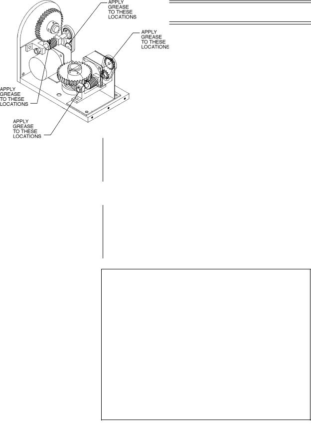
Sprockets, chains, and gears should be well greased. If necessary, lubricate the pan and tilt gears, sprockets, and chains as follows with a high-quality grease capable of withstanding temperatures from -50° to 170°F (-46° to 77°C). Do the following:
1.Liberally apply grease to the pan and tilt gears, chains, and sprockets (refer to Figure 1).
2.Operate the pan and tilt motors to spread the grease across the parts.
Figure 1. Servicing the Pan/Tilt
6 |
Pelco Manual C325SM (3/99) |
IMPORTANT: Be very careful when resetting potentiometer switches. Be sure that the pan/tilt has been centered between maximum pan and tilt travel, regardless of the adjustable limit stops. Failure to observe caution when resetting potentiometers could result in damage to the preset positioning ability of the pan/tilt.
WARNING: NEVER reposition the pan fixed limit stop. Doing so WILL DAMAGE the wiring harness and, if the pan/tilt has preset positioning, COULD cause the pan potentiometer to BREAK.
3.Apply additional grease if necessary.
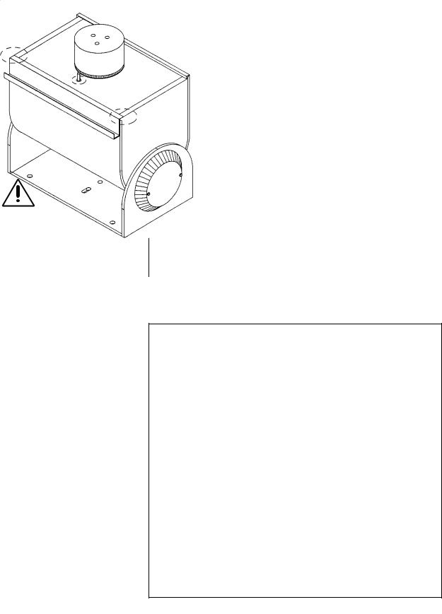
4.Reinstall the cover. If the pan/tilt is installed outdoors in an inverted position, apply RTV silicone sealant as shown in Figure 2.
3.2RESETTING POTENTIOMETERS
Models with Preset Positioning (PP)
Models with preset positioning (PP) use potentiometer switches that are factory set to the full range of pan and tilt travel. Under normal operating conditions and at routine service intervals they do not need adjusting.
Should your pan/tilt require any work on the drive mechanism other than routine maintenance, perform the following procedure to reset the potentiometers.
To begin, remove the three screws on the front of the pan/tilt housing and lift the cover to gain access to the pan and tilt motor assemblies.
1.Remove the potentiometer gears and position the pan/tilt to the middle of its maximum pan and tilt travel, regardless of the position of the adjustable limit stops. That is, the tilt table should be level and the fixed limit stop should be opposite the limit switch.
2.Turn a potentiometer all the way in one direction until it stops, then observing the number of turns, turn it back the other way until it stops. Rotate the potentiometer half the number of turns the other way to reach the center.
3.Replace the potentiometer gear.
4.Perform steps 2 and 3 for the other potentiometer.
Figure 2. Sealant Locations
Pelco Manual C325SM (3/99) |
7 |

4.0 EXPLODED ASSEMBLY DIAGRAMS
Figure 3. PT550P Series Exploded Assembly Diagram
8 |
Pelco Manual C325SM (3/99) |
Table A. PT550P Series Parts List
Item |
Qty |
Description |
Part Number |
|
|
|
|
1 |
1 |
Gasket Conn PT1000L-1 |
105010010 |
2 |
4 |
Ring, Snap #Q2-18 |
15510000 |
3 |
2 |
Pin Dowel 1/8" x 5/8" Hardened Steel |
15510001 |
4 |
4 |
Gasket 1/8" x 1/2" #G207N x Feet |
15510002 |
5 |
2 |
Pin Dowel 1/8" x 1/2" Hardened Steel |
15510003 |
6 |
1 |
Body assembly |
1551008COMP |
7 |
1 |
Tilt shaft assembly |
1551009COMP |
8 |
2 |
Bracket, PC board filter |
1554000COMP |
9 |
1 |
Tilt table |
1554037COMP |
10 |
1 |
Cover |
1554041COMP |
11 |
1 |
Pull up bar |
1554042COMP |
12 |
1 |
Gear, tilt |
1554044COMP |
13 |
1 |
Hub tilt gear |
1554045COMP |
14 |
1 |
Plate backup, tilt gear |
1554046COMP |
15 |
1 |
Spacer, body sides |
1554047COMP |
16 |
1 |
Gear, pan |
1554048COMP |
17 |
1 |
Pin, pan limit |
1554049COMP |
18 |
1 |
Pin, tilt limit |
1554049TCOMP |
19 |
2 |
Tilt limit stop |
1554050COMP |
20 |
1 |
Bracket, pan limit |
1554051COMP |
21 |
1 |
Bracket, tilt limit |
1554052COMP |
22 |
2 |
Cover plate, tilt shaft |
1554053COMP |
23 |
2 |
Bearing, ball, 5/16 dia. |
1556000 |
24 |
2 |
Bearing |
1556004 |
25 |
2 |
Motor, gearhead, 115 VDC |
1558004A |
26 |
1 |
Pin, #3 Taper x 1 1/4" |
17510001 |
27 |
2 |
Chain motor assembly |
1751002COMP |
28 |
2 |
Sprocket |
17512004 |
29 |
2 |
Screw, worm shaft thrust adjust |
1754005COMP |
30 |
2 |
Sprocket |
1754022COMP |
31 |
2 |
Plate, motor |
1754062COMP |
32 |
2 |
Shaft, worm gear |
1754063COMP |
33 |
1 |
Locknut, No. 5 |
2504012COMP |
34 |
2 |
Bearing, pan spindle |
2506000 |
35 |
1 |
Spindle, base assembly |
5501021COMP |
36 |
3 |
Limit stop, pan |
58010006 |
37 |
1 |
Gear, tilt |
7712006 |
38 |
1 |
Gear, pan |
7712007 |
39 |
2 |
Bearing, cage only |
776001 |
40 |
4 |
Bearing, washer only |
776002 |
41 |
2 |
Bearing |
776003 |
42 |
2 |
Grommet, neoprene |
GRO2172N |
43 |
2 |
PC Board pan/tilt filter |
PCB5500126B |
44 |
4 |
Switch |
SWI1SM1 |
45 |
4 |
Switch actuator with insulator |
SWIJS138B |
46 |
2 |
Bracket, AZL pot (PT550P/PP only) |
1754000COMP |
47 |
2 |
Gear, PP pot shaft (PT550P/PP only) |
1754003COMP |
48 |
2 |
Sprocket, motor (PT550P/PP only) |
1754004COMP |
49 |
2 |
Gear (PT550P/PP only) |
1754006COMP |
50 |
2 |
Pot, Model 534, 5K ohm |
POT005.0K10534 |
51 |
1 |
Bolt, 1/4 - 20 x 5/8" hex cad |
ZH1/420X.625CH |
52 |
6 |
Set screw, 10-32 x 5/16" soc knur black |
ZH10-32X.187S |
53 |
1 |
Set screw, 10-32 x 5/16" soc knur black |
10-32X.312S |
54 |
10 |
Washer, flat #10 |
ZH204X436X60 |
55 |
8 |
Screw, 2.56 x 1/2" pan phil SS |
ZH2-56X.500SPP |
56 |
|
Not Used |
|
57 |
1 |
Washer, flat 3/16" VSS SPL - size plt D |
ZH260X562X65C |
58 |
4 |
Screw 4-40 x 3/8" pan phil SS |
ZH4-40X.250SPP |
59 |
4 |
Screw 4-40 x 3/8" pan phil SS |
ZH4-40X.375SPP |
60 |
2 |
Washer, flat 1/2 AN - 960-816 |
ZH515X.875X62 |
61 |
4 |
Screw, 6-32 x 1/4" pan phil SS |
ZH6-32X.250SPP |
|
|
|
|
Continued on next page
Pelco Manual C325SM (3/99) |
9 |
Table A. PT550P Series Parts List (continued)
Item |
Qty |
Description |
Part Number |
|
|
|
|
62 |
3 |
Screw, 6-32 x 3/8" soc cad |
ZH6-32X.375CS |
63 |
3 |
Screw, 6-32 x 3/8" pan slot SS |
ZH6-32 X.375SPS |
64 |
2 |
Screw, 6-32 x 5/8" flat slot SS |
ZH6-32X.625SFS |
65 |
4 |
Set screw, 6-32 x 3/4" SS |
ZH6-32X.750SS |
66 |
4 |
Nut, 6-32 a corn brass chrome |
ZH6-32XNUTCA |
67 |
4 |
Nut, hex 6-32 SS |
ZH6-32XNUTSH |
68 |
4 |
Washer, internal star #6 SS |
ZH6LWSIS |
69 |
3 |
Washer, split lock #6 SS |
ZH6LWSSL |
70 |
12 |
Screw, 8-32 x 1/2" soc cad |
ZH8-32X.500CS |
71 |
2 |
Screw, 8-32 x 1/2" pan slot SS |
ZH8-32X.500SPS |
72 |
3 |
Screw, 8-32 x 5/8" soc cad |
ZH8-32X.625CS |
73 |
3 |
Screw, 8-32 x 3/4" pan slot SS |
ZH8-32X.750SPS |
74 |
3 |
Nut, Hex 8-32 SS |
ZH8-32XNUTSH |
75 |
3 |
Washer, internal #8" SS |
ZH8LWSIS |
76 |
15 |
Washer, split lock #8" SS |
ZH8LWSSL |
77 |
2 |
Pin, roll 3/32 x 1/2" |
ZHPIN3/32X1/2R |
78 |
2 |
Pin, roll 3/32 x 3/8" |
ZHPIN3/32X3/8R |
|
|
|
|
10 |
Pelco Manual C325SM (3/99) |
Loading...