


A D D E N D U M
Addendum No.:
Date:
Manuals Affected:
Manual Update:
C1588M
May 5, 2005
KBD300A Universal Keyboard – C527M-L
KBD4000 Genex Multiplexer Keyboard - C1921M-G
ECO 05-10910 optimizes joystick performance whenever you power up the KBD300A and KBD4000. It also provides an automatic calibration mode.
Automatic Calibration of the Joystick
The KBD300A and KBD4000 will calibrate the joystick automatically on power-up and every 30 minutes of inactivity. This is the default operation of the keyboard and will ensure optimal joystick performance. Make sure the joystick remains in the center position as power is applied to the keyboard. Do not move or hold down the joystick until after the red LEDs have finished flashing the software version number.
Worldwide Headquarters • 3500 Pelco Way • Clovis, California 93612 USA • www.pelco.com USA & Canada • Tel: 800/289-9100 • Fax: 800/289-9150
International • Tel: 1-559/292-1981 • Fax: 1-559/348-1120
®
KBD4000
Genex® Multiplexer
Keyboard
Installation/
Operation Manual
C1921M-G (1/04)
Pelco World Headquarters • 3500 Pelco Way, Clovis, CA 93612-5699 USA • www.pelco.com
USA & Canada: Tel: 800/289-9100 • Fax: 800/289-9150
International: Tel: 1-559/292-1981 • Fax: 1-559/348-1120
2 |
Pelco Manual C1921M-G (1/04) |

CONTENTS
Section |
|
|
|
|
|
Page |
||||
IMPORTANT SAFEGUARDS AND WARNINGS ........................................................................ |
|
|
|
|
|
4 |
||||
REGULATORY NOTICES ........................................................................................................... |
|
|
|
|
|
4 |
||||
DESCRIPTION ........................................................................................................................... |
|
|
|
|
|
5 |
||||
INSTALLATION ........................................................................................................................... |
|
|
|
|
|
6 |
||||
MODES OF OPERATION .................................................................................................. |
|
|
|
|
|
6 |
||||
DO A MULTIPLEXER MODE INSTALLATION ........................................................... |
|
|
|
|
|
6 |
||||
DO A MULTIPLEXER SERVER MODE INSTALLATION ........................................... |
|
|
8 |
|||||||
CHECK THESE THINGS ................................................................................................... |
|
|
|
|
|
9 |
||||
MULTIPLEXER .......................................................................................................... |
|
|
|
|
|
9 |
||||
MULTIPLEXER SERVER .......................................................................................... |
|
|
|
|
|
9 |
||||
SETTING COAXITRON CONTROL OF CAMERAS ......................................................... |
|
|
|
|
|
10 |
||||
WHAT’S NEXT? ................................................................................................................ |
|
|
|
|
|
10 |
||||
PROGRAMMING ....................................................................................................................... |
|
|
|
|
|
11 |
||||
CONTROLLING THE MULTIPLEXER WITH THE KEYBOARD ....................................... |
|
|
11 |
|||||||
PASSWORD ...................................................................................................................... |
|
|
|
|
|
11 |
||||
MENUS ............................................................................................................................. |
|
|
|
|
|
12 |
||||
SYSTEM SETUP (VIEW KEY) ................................................................................. |
|
|
|
|
|
13 |
||||
ADVANCED SYSTEM SETUP (VIEW KEY) ............................................................ |
|
|
|
|
|
15 |
||||
RECORD SETUP (LIVE/VCR KEY) ......................................................................... |
|
|
|
|
|
18 |
||||
CUSTOM VCR SETUP (LIVE/VCR KEY) ................................................................. |
|
|
|
|
|
20 |
||||
CAMERA SETUP (NUMBER AND CAM KEYS) ....................................................... |
|
|
|
|
|
21 |
||||
ACTIVITY DETECTION MASK SETUP .................................................................... |
|
|
|
|
|
23 |
||||
SEQUENCE SETUP (SEQ KEY) ............................................................................. |
|
|
|
|
|
24 |
||||
HELP MENU ............................................................................................................. |
|
|
|
|
|
25 |
||||
ALARM LOG ............................................................................................................. |
|
|
|
|
|
25 |
||||
MULTIPLE CAMERA DISPLAY SETUP ............................................................................ |
|
|
|
|
|
26 |
||||
PROGRAMMING THE PICTURE-IN-PICTURE DISPLAY ( |
|
|
26 |
|||||||
|
) |
|||||||||
|
|
|
|
|
|
|
|
|
|
|
PROGRAMMING THE 4-CAMERA DISPLAY ( |
|
|
|
|
) |
............................................... |
|
|
26 |
|
|
|
|
|
|
|
|||||
|
|
|
|
|
|
|
|
|
|
|
|
|
|
|
|
|
|
|
|
|
|
PROGRAMMING THE 9-CAMERA DISPLAY ( |
|
|
|
|
|
) |
|
|
|
27 |
|
|
|
|
|
|
|
||||
|
|
|
|
|
|
|
|
|
|
|
|
|
|
|
|
|
|
|
|
|
|
PROGRAMMING THE 16-CAMERA DISPLAY ( |
|
|
|
|
|
) |
|
|
27 |
|
|
|
|
|
|
|
|
||||
|
|
|
|
|
|
|
||||
|
|
|
|
|
|
|
|
|
|
|
PROGRAMMING MENU DEFAULTS ............................................................................... |
|
|
|
|
|
28 |
||||
PROGRAMMING A PRESET ............................................................................................ |
|
|
|
|
|
29 |
||||
PROGRAMMING A PATTERN .......................................................................................... |
|
|
|
|
|
29 |
||||
OPERATION .............................................................................................................................. |
|
|
|
|
|
30 |
||||
TROUBLESHOOTING ............................................................................................................... |
|
|
|
|
|
38 |
||||
SPECIFICATIONS ..................................................................................................................... |
|
|
|
|
|
39 |
||||
INDEX ........................................................................................................................................ |
|
|
|
|
|
40 |
||||
WARRANTY AND RETURN INFORMATION ............................................................................ |
|
|
|
|
|
42 |
||||
LIST OF ILLUSTRATIONS
Figure |
|
Page |
1 |
Connecting Keyboard to Multiplexer .......................................................................... |
6 |
2 |
Connecting Keyboards to the Server ......................................................................... |
8 |
3 |
Multiplexer Front Panel ............................................................................................. |
11 |
4 |
Menu Tree ................................................................................................................ |
12 |
5 |
Basic System Setup Menu ....................................................................................... |
13 |
6 |
Advanced System Setup Menu ................................................................................ |
15 |
7 |
Basic VCR Setting Menu .......................................................................................... |
18 |
8 |
Custom VCR Setup Menu ........................................................................................ |
20 |
9 |
Basic Camera Menu ................................................................................................. |
21 |
10 |
Activity Detection Mask ............................................................................................ |
23 |
11 |
Camera Sequencing Menu ....................................................................................... |
25 |
12 |
Help Menu ................................................................................................................ |
25 |
13 |
KBD4000 Keyboard Definitions ................................................................................ |
30 |
LIST OF TABLES
Table |
|
Page |
A |
Camera Numbers with Switch 7 ON |
.......................................................................... 7 |
B |
Keyboard Addresses ................................................................................................. |
8 |
C |
VCR Types ............................................................................................................... |
19 |
D |
Programming Menu Defaults .................................................................................... |
28 |
E |
Operation Guide ....................................................................................................... |
31 |
Pelco Manual C1921M-G (1/04) |
3 |

IMPORTANT SAFEGUARDS AND WARNINGS
Prior to installation and use of this product, the following WARNINGS should be observed.
1.Installation and servicing should only be done by qualified service personnel and conform to all local codes.
2.Unless the unit is specifically marked as a NEMA Type 3, 3R, 3S, 4, 4X ,6 or 6P enclosure, it is designed for indoor use only and it must not be installed where exposed to rain and moisture.
3.Only use replacement parts recommended by Pelco.
4.After replacement/repair of this unit’s electrical components, conduct a resistance measurement between line and exposed parts to verify the exposed parts have not been connected to line circuitry.
REGULATORY NOTICES
This equipment has been tested and found to comply with the limits of a Class B digital device, pursuant to part 15 of the FCC rules. These limits are designed to provide reasonable protection against harmful interference in a residential installation. This equipment generates, uses, and can radiate radio frequency energy and, if not installed and used in accordance with the instructions, may cause harmful interference to radio communications. However there is no guarantee that the interference will not occur in a particular installation. If this equipment does cause harmful interference to radio or television reception, which can be determined by turning the equipment off and on, the user is encouraged to try and correct the interference by one or more of the following measures:
•Reorient or relocate the receiving antenna.
•Increase the separation between the equipment and the receiver.
•Connect the equipment into an outlet on a circuit different from that to which the receiver is connected.
•Consult the dealer or an experienced radio/TV technician for help.
4 |
Pelco Manual C1921M-G (1/04) |

DESCRIPTION
The KBD4000 Genex® Multiplexer Keyboard is a full-function keyboard controller for the
MX4000 Genex Multiplexer and MX4000SVR Genex Multiplexer Server.
This manual covers the KBD4000 keyboard’s operation with both duplex and simplex models of the multiplexer. The differences, as they pertain to the keyboard, are indicated as necessary.
The mode of operation depends on whether the keyboard is connected to a multiplexer or to a server. (See Modes of Operation for an explanation.)
In addition to performing all the control functions that can be done from the multiplexer’s front panel, the keyboard features a three-axis joystick and additional keys to control fixed and variable speed pan, tilt, and lens functions. The keyboard can also operate presets, auxiliaries, and patterns and can be used to program the multiplexer or server.
IMPORTANT DIFFERENCES IN SIMPLEX AND DUPLEX MULTIPLEXER
OPERATING MODES.
The simplex multiplexer has three operating modes:
Live The main monitor can show live video both in full-screen or multi-screen views. You cannot record in live mode. The multiplexer’s DISPLAY/ RECORD LED is off.
VCR The main monitor shows full-screen or multi-screen views of videotape playback. You cannot record in VCR mode. The multiplexer’s DISPLAY/
RECORD LED is off.
Record The main monitor shows live video of an individual camera in full-screen view only. You can record only when in record mode. While recording, all cameras are being recorded simultaneously. The multiplexer’s DISPLAY/
RECORD LED is on.
The duplex multiplexer has two operating modes:
Live The main monitor shows live video both in full-screen or multi-screen views.
You can record while viewing any or all cameras. While recording, all cameras are being recorded simultaneously. The multiplexer’s LIVE/VCR
LED is on.
VCR The main monitor shows full-screen or multi-screen views of videotape playback. You can record in VCR mode if you have a second VCR connected to the VCR OUT jack on the multiplexer. The multiplexer’s LIVE/VCR
LED is off.
Pelco Manual C1921M-G (1/04) |
5 |

INSTALLATION
The following parts are supplied:
1 KBD4000 keyboard
1 25-foot (7.6 m) data cable
1 MODES OF OPERATION
The mode of operation depends on whether the keyboard is connected to a multiplexer or to a server.
Multiplexer Mode |
A single keyboard is plugged into the back of a Genex |
|
MX4000 Multiplexer. |
Multiplexer Server Mode |
Up to four keyboards can be connected to the back of a |
|
Genex MX4000SVR Multiplexer Server. Each keyboard |
|
connected to the remote keyboard port requires a |
|
KBDKIT(-X). |
Proceed to the Do A Multiplexer Mode Installation section (step 1A) or Do A Multiplexer
Server Mode Installation section (step 1B).
1A DO A MULTIPLEXER MODE INSTALLATION
|
|
|
|
|
|
|
|
|
|
PIN 1 |
|
|
|
|
|
|
|
|
|
|
|
|
RJ-45 |
|
|
|
|
|
|
|
|
|
|
|
|
JACK PINOUTS |
||
|
|
|
|
|
|
|
|
|
1 |
TX+ |
5 GND |
|
|
|
|
|
|
|
|
|
|
2 |
TX— |
6 |
|
|
|
|
|
|
|
|
|
|
3 |
12 VAC/DC |
7 |
RX— |
|
|
|
|
|
|
|
|
|
4 |
}NONPOLAR |
8 |
RX+ |
SPOT MAIN |
VCR |
IN |
|
COM |
OUT N NH |
|
|
|
||||
|
|
|
|
|
|
|
|
|
OCC S |
|
|
|
AUX |
OUT |
IN |
|
|
|
|
|
|
|
|
|
|
|
|
ALARMS |
|
|
|
|
|
|
||||
SVHS |
SVHS |
1 |
2 |
3 |
4 |
5 |
6 7 |
8 |
9 10 11 12 1314 1516 |
110-240V 50/60 Hz |
|
00018 |
|
|
|||||||||||
|
|
|
|
|
|
|
|
|
|
|||
Figure 1. Connecting Keyboard to Multiplexer
1.Remove the DIP switch cover plate from the rear of the keyboard (refer to Figure 1).
2.Set the switches (refer to Figure 1 for switch locations).
ADDRESS
Set switches 1, 2, and 3 OFF. This is address 0, which selects the multiplexer operating mode.
COMMUNICATION MODE
•Set switch 4 OFF to enable polled communication mode. Use this for normal keyboard operation.
•Set switch 4 ON to put the keyboard in non-polled communication mode. Use this when the keyboard communicates remotely over communications media that do not support polled mode. These are any communications media that introduce significant delay in transmitting data (for example, phone line transmission systems). In non-polled mode, the keyboard can control multiplexers only. The multiplexer server does not support non-polled mode.
6 |
Pelco Manual C1921M-G (1/04) |

NOTE: For distances over 25 feet (7.6 m), you must order the KBDKIT(-X) Remote Keyboard Wiring Kit. Refer to the KBDKIT(-X) manual for installation procedures.
UNUSED
Leave switch 5 OFF. It is not used.
TURBO MODE
Set switch 6 ON to enable the turbo (extra fast) pan feature or OFF to disable.
CAMERA ADDRESS MODE
There are two modes for addressing cameras:
•Set switch 7 ON if you want to address all cameras consecutively from 1-256 (refer to Table A).
•Set switch 7 OFF if you want to address cameras in groups of 16 according to the multiplexer to which they are connected. For example, multiplexer 1, cameras 1-16; multiplexer 2, cameras 1-16, etc.
Table A. Camera Numbers with Switch 7 ON
Multiplexer |
|
Cameras |
|
|
9-channel |
|
16-channel |
|
|
||
|
|
|
|
1 |
1-9 |
|
1-16 |
2 |
17-25 |
|
17-32 |
3 |
33-41 |
|
33-48 |
4 |
49-57 |
|
49-64 |
5 |
65-73 |
|
65-80 |
6 |
81-89 |
|
81-96 |
7 |
97-105 |
|
97-112 |
8 |
113-121 |
|
113-128 |
9 |
129-137 |
|
129-144 |
10 |
145-153 |
|
145-160 |
11 |
161-169 |
|
161-176 |
12 |
177-185 |
|
177-192 |
13 |
193-201 |
|
193-208 |
14 |
209-217 |
|
209-224 |
15 |
225-233 |
|
225-240 |
16 |
241-249 |
|
241-256 |
|
|
|
|
PROGRAMMING MODE
Set switch 8 ON to program the multiplexer and camera presets and patterns from the keyboard. Set to OFF to disable programming.
3.Replace the cover on the back of the keyboard.
4.The keyboard comes with a 25-foot (7.6 m) data cable with RJ-45 connectors. Plug one end into the back of the keyboard and the other end into the COM IN connector on the back of the multiplexer. Refer to Figure 1.
The keyboard receives power from the multiplexer. The LED display lights momentarily when the keyboard receives power and stays on when you enter a multiplexer address.
The KBD4000 has calibrating software for automatically centering the joystick. Be certain the joystick remains in the neutral (vertical) position as power is applied to the keyboard. Do not move or hold down the joystick until after the red digit LEDs have finished flashing the firmware revision.
5.Peel off the protective covering over the LED display in the keyboard’s upper left corner.
Pelco Manual C1921M-G (1/04) |
7 |
1B DO A MULTIPLEXER SERVER MODE INSTALLATION
ADDRESS #1 (LOCAL)
CONTROLS MONITOR 1
|
LOCAL |
|
|
|
|
|
|
|
|
KEYBOARD |
|
|
|
|
|
|
|
|
|
|
|
|
ADDRESS #2 (REMOTE) |
||||||
|
|
|
CONTROLS MONITOR 2 |
||||||
T+ T |
R- R+ |
|
|
|
|
|
|
|
|
|
ON |
1 |
2 |
3 |
4 |
5 |
6 |
7 |
ON |
|
|
|
|
|
|
|
|
1 |
TX+ |
|
|
|
|
|
|
|
|
2 |
TX- |
|
|
|
|
|
|
|
|
3 |
12VAC |
|
|
|
|
|
|
|
|
4 |
12VAC |
|
|
|
|
|
|
|
|
5 |
GND |
|
|
|
|
|
|
|
|
6 |
NC |
|
|
|
|
|
|
|
|
7 |
RX- |
|
KBDKIT |
|
|
|
|
|
|
MULTIPLEXER |
|
|
|
|
|
|
|
|
WALL BLOCK |
||
|
|
|
|
|
|
|
|
||
|
|
|
|
|
|
|
|
ON |
1 |
2 |
3 |
4 |
5 |
6 |
7 |
|
|
|
|
|
|
|
|
|
|
|
|||||||
|
ADDRESS #3 (REMOTE) |
|
|
ADDRESS #4 (REMOTE) |
||||||||||||
|
CONTROLS MONITOR 3 |
|
|
CONTROLS MONITOR 4 |
||||||||||||
1 |
2 |
3 |
4 |
5 |
6 |
7 |
|
ON |
1 |
2 |
3 |
4 |
5 |
6 |
7 |
|
|
|
|
|
|
|
1 |
TX+ |
|
|
|
|
|
|
|
1 |
TX+ |
|
|
|
|
|
|
2 |
TX- |
|
|
|
|
|
|
|
2 |
TX- |
|
|
|
|
|
|
3 |
12VAC |
|
|
|
|
|
|
|
3 |
12VAC |
|
|
|
|
|
|
4 |
12VAC |
|
|
|
|
|
|
|
4 |
12VAC |
|
|
|
|
|
|
5 |
GND |
|
|
|
|
|
|
|
5 GND |
|
|
|
|
|
|
|
6 |
NC |
|
|
|
|
|
|
|
6 NC |
|
|
|
|
|
|
|
7 |
RX- |
|
|
|
|
|
|
|
7 |
RX- |
|
|
|
|
|
|
|
4 |
5 |
|
|
|
|
|
|
|
|
|
|
|
|
|
|
|
3 |
6 |
|
|
|
|
|
|
|
|
|
|
|
|
|
|
|
2 |
7 |
|
|
|
|
|
|
|
|
|
|
|
|
|
|
|
1 |
8 |
|
|
|
|
|
|
|
|
00017
Figure 2. Connecting Keyboards to the Server
If the keyboard will be connected to a server that will operate in paired mode configuration, only addresses 1 and 3 can be used. Refer to the server manual for information about paired mode configuration.
1.Remove the DIP switch cover plate from the rear of the keyboard (refer to Figure 1).
2.Set the switches (refer to Figure 1 for switch locations).
ADDRESS
Set the keyboard address according to Table B.
Table B. Keyboard Addresses
Keyboard |
|
|
Switch Settings |
|
|
Address |
1 |
|
2 |
|
3 |
|
|
||||
1 |
ON |
|
OFF |
|
OFF |
2 |
OFF |
|
ON |
|
OFF |
3 |
ON |
|
ON |
|
OFF |
4 |
OFF |
|
OFF |
|
ON |
UNUSED
Switches 4 and 5 must be set OFF. They are not used in multiplexer server mode.
TURBO MODE
Set switch 6 ON to enable the turbo (extra fast) pan feature or OFF to disable.
CAMERA ADDRESS MODE
There are two modes for addressing cameras:
•Set switch 7 ON if you want to address all cameras consecutively from 1-256 (refer to Table A).
•Set switch 7 OFF if you want to address cameras in groups of 16 according to the multiplexer to which they are connected. For example, multiplexer 1, cameras
1-16; multiplexer 2, cameras 1-16, etc.
PROGRAMMING MODE
Set switch 8 ON to program the multiplexer and server and OFF to disable programming.
8 |
Pelco Manual C1921M-G (1/04) |

3.Replace the cover on the back of the keyboard.
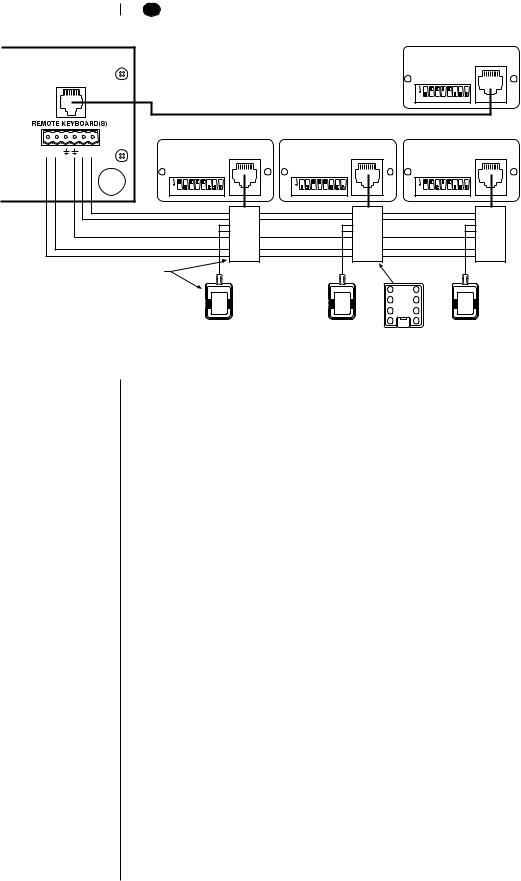
4.Connect the keyboard to the MX4000SVR Multiplexer Server.
You can connect up to four keyboards to the server—one to the server’s LOCAL KEYBOARD port and three to its REMOTE KEYBOARD(S) port, or all four to the remote.
LOCAL KEYBOARD PORT CONNECTION
Plug one end of the 25-foot (7.6 m) data cable with RJ-45 connectors supplied with the keyboard into the back of the keyboard. Plug the other end into the LOCAL KEYBOARD port on the server. Refer to the multiplexer server manual for instructions.
The keyboard receives power from the multiplexer, as indicated by a lighted LED display. The display shows the address of the multiplexer with which the keyboard is communicating.
REMOTE KEYBOARD(S) PORT CONNECTION
You must order a KBDKIT(-X) for each keyboard you intend to connect to the server’s
REMOTE KEYBOARD(S) port. Follow the instructions supplied with the kit. Refer to Figure 1 for the keyboard RJ-45 pin-outs.
The keyboard receives power from the transformer, as indicated by a lighted LED display. The display shows the address of the multiplexer with which the keyboard is communicating.
The KBD4000 has calibrating software for automatically centering the joystick. Be certain the joystick remains in the neutral (vertical) position as power is applied to the keyboard. Do not move or hold down the joystick until after the red digit LEDs have finished flashing the firmware revision.
5.Peel off the protective covering over the LED display in the keyboard’s upper left corner.
IMPORTANT: The keyboard is ready to operate when plugged into a multiplexer or multiplexer server.
However, some minimal programming may be required to make your system work. Do not assume there is nothing more to do after connecting the keyboard to the system.
2 CHECK THESE THINGS
2A MULTIPLEXER
Below are the minimum things to check.
1.If you have more than one multiplexer, each one must have its own address (UNIT ID in the Advanced System Setup menu). If you have a server, the multiplexer address must match the input on the server to which it is connected. For example, if the multiplexer is connected to input 3 on the server, set the multiplexer address to 3.
2.Set the master/slave designation to let the keyboard communicate with multiplexers.
•In polled mode (switch 4 OFF), you must designate one multiplexer (any one) as the master and all the others as slaves. If you have just one multiplexer, it must be the master.
•In non-polled communication mode (switch 4 ON), all multiplexers must be slaves (the keyboard is the master).
Set the address and master/slave designation from the front panel of the multiplexer, not from the keyboard. For instructions, refer to Controlling the Multiplexer with the Keyboard in the Programming section.
2B MULTIPLEXER SERVER
Below is the minimum you should check.
If you intend to control two monitors from one keyboard (paired mode), you must change the settings for the monitors (Monitor menu). Programming the server can only be done from the keyboard. Refer to the server manual for instructions.
Pelco Manual C1921M-G (1/04) |
9 |
3 SETTING COAXITRON® CONTROL OF CAMERAS
NOTE: If you have a multiplexer server, you must enter the Camera menu from the multiplexer’s front panel. Then you can program the cameras from the front panel of the multiplexer or from the keyboard.
The KBD4000 keyboard provides Coaxitron control of pan, tilt, and lens functions. There are three Coaxitron format settings, which are set in the Camera Setup section.
Standard Use for moveable cameras controlled by 15-bit standard Coaxitron receivers, such as the CX9000 Series, the PT7700, and the ED25/27/ 28/29. The KBD4000 keyboard, in conjunction with a Genex multiplexer, supports all pan, tilt, and lens functions, and auxiliary on/off.
The keyboard does not set or call presets or support preset scanning.
Extended Use for moveable cameras controlled by 32-bit extended Coaxitron (Default) receivers, such as Esprit®, Intercept®, Spectra®, and the LRD41C21/
LRD41C22 Series. The KBD4000 keyboard, in conjunction with a
Genex multiplexer, supports all 15-bit functions, plus the setting and calling of presets and patterns. A different control, such as the MPT9500, is required to program labels for presets and patterns.
Off |
Use for fixed cameras. |
4 WHAT’S NEXT?
At this point you can work through the Programming section or proceed directly to the
Operating section.
10 |
Pelco Manual C1921M-G (1/04) |
PROGRAMMING
NOTE: To program a multiplexer if a multiplexer server is installed, you must enter programming mode from the multiplexer’s front panel.
After doing so, you can program the multiplexer through its front panel or you can navigate and make programming selections through the keyboard.
This section applies only to programming the multiplexer. The multiplexer can be programmed from the keyboard or from the multiplexer’s front panel. To program the multiplexer from the front panel, refer to the multiplexer manual. To program the multiplexer server, refer to the server manual.
Programming lets you configure the multiplexer (from the KBD4000) for the way you want your system to operate. The multiplexer automatically selects the most common operating parameters. However, some minimal programming may be required to make your system work.
Programming of system, camera, and VCR setup; camera sequencing; and alarm and activity detection is done through on-screen menus displayed on the main monitor. You can enable a password to prevent unauthorized access to the menus.
Programming of the picture-in-picture, and 4-, 9-, and 16-camera displays can be done directly without going through menus. (Refer to the Multiple Camera Display Setup section.
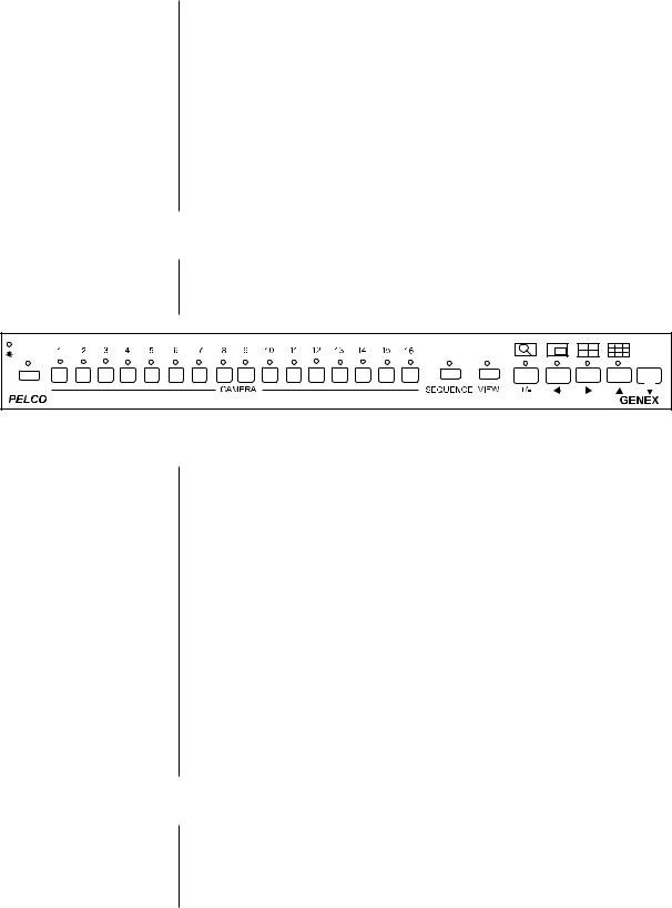
CONTROLLING THE MULTIPLEXER WITH THE KEYBOARD
IMPORTANT INSTRUCTIONS
Before you can use the keyboard to control the multiplexer(s), do the following at the front panel of the multiplexer(s).
VCR |
LIVE |
Duplex Color Multiplexer |
00019 |
Figure 3. Multiplexer Front Panel
IMPORTANT: The Genex multiplexer lets you work in any of four languages: English (default), French, German, or Spanish. If you need to change the language, do so before programming because you must reset the multiplexer to factory defaults before you can change the language. See the MX4000 Genex Series Simplex and Duplex Multiplexers Installation/ Operation Manual for details.
1.Press the VIEW button for about three seconds. The basic System Setup menu appears and the currently selected menu item blinks.
2.Use the arrow buttons to highlight ADVANCED SETUP.
3.Press the +/- button. The Advanced System Setup menu appears. Skip steps 4 and 5 if your system has only one multiplexer.
4.Use the arrow buttons to move the cursor to UNIT ID.
5.Press the +/- button to select the multiplexer’s UNIT ID.
6.Use the arrow buttons to move the cursor to COMM TYPE.
•In polled communication mode (switch 4 off), one multiplexer must be the master and all others slaves.
•In non-polled mode (switch 4 on), all multiplexers must be slaves (the keyboard is master).
7.Use the arrow buttons to go to EXIT. Press the +/- button to exit the menu. You can now use the keyboard to program the multiplexer(s).
PASSWORD
You can program the multiplexer to request a password for access to programming menus.
Refer to the Advanced System Setup section for information on enabling the password.
The universal password is 3916 and cannot be changed. You must enter this password whenever the system requests one. Enter it from the keyboard by pressing each number followed by the CAM key (3, CAM, 9, CAM, 1, CAM, 6, CAM).
Pelco Manual C1921M-G (1/04) |
11 |

MENUS
|
LIVE/VCR |
|
|
|
|
|
MONITOR |
|
|
|
|
UNIT |
MAIN |
SPOT |
SEQ |
VIEW PATTERN PRESET ON |
OFF |
1 |
2 |
3 |
NEAR |
FAR |
|
|
|
|
|
||
4 |
5 |
6 |
OPEN |
CLOSE |
|
|
|
|
|
||
7 |
8 |
9 |
|
|
|
CAM |
0 |
CLEAR |
|
|
|
CAMERA 1 NORMAL
VIDEO INPUT TERMINATION 75 OHM
ALARM INPUT NORMALLY |
OPEN |
|
|
||||||
COAXITRON FORMAT |
OFF |
|
|
||||||
ACTIVITY DETECTION |
|
|
|
||||||
ENABLED |
|||||||||
SET DETECTION MASK |
|
|
|
|
|
|
|||
|
|
|
|
|
|
|
|
|
|
ACTIVITY DETECTION MED SENSITIVITY
SET ALL 
 CLEAR ALL
 EXIT
EXIT 
 TEST
TEST
GROUP |
|
NINE (3x3) |
QUAD (2x2) |
|
04 |
1 |
04 |
04 |
204
304
|
HELP |
BUTTON |
SETTING |
* VCR/LIVE |
VCR SPEED & ALARM |
|
QUICK SETUP |
|
MONITOR SETUP |
+/– |
- SINGLE PRESS MODIFY |
|
DOUBLE PRESS CHANGE |
|
EDIT DIRECTION |
HOLD BUTTONS TO ENTER/EXIT
THEIR ASSOCIATED MENU
USE ARROWS TO NAVIGATE
|
|
|
|
|
|
|
NORMAL REC. SPEED |
2/6/8 Hr |
|
||||
ALARM REC. SPEED |
2/6/8 Hr |
|
||||
|
|
|
|
VCR SETUP |
||
VCR TYPE |
UNIVERSAL |
|||||
VCR VIDEO FORMAT |
COMPOSITE |
|||||
VCR SWITCH PULSE |
DISABLED |
|||||
|
|
|
ALARM HANDLING |
|||
RECORD ALARMS AS A |
PRIORTIY |
|||||
ALARM RECORD TIME |
ALARM DURATION |
|||||
CONFIGURE CUSTOM VCR |
||||||
PLAYBACK FORMAT |
PELCO |
|||||
|
|
|
|
|
|
|
NORMAL RECORD SETUP
RECORD SPEED 2/6/8 Hr
SWITCH INTERVAL 003
ALARM RECORD SETUP
RECORD SPEED 2/6/8 Hr
SWITCH INTERVAL 003
|
|
|
|
|
|
|
|
EXIT |
|
|
|
|
BACK |
||
|
|
|
|
|
|
|
|
|
|
|
|
|
|
|
|
|
|
|
|
|
|
|
|
|
|
|
|
|
|
|
|
|
|
|
|
|
|
|
|
|
|
|
|
|
|
|
|
|
|
|
|
|
|
|
|
|
2/6/8 Hr |
|
|
||||
|
|
|
|
|
|
|
|
|
2/6/8 Hr |
|
|
|
|
|
|
MAIN MONITOR VIDEO |
|
|
|
|
|
|
|
|
|||||||
MAIN MONITOR DISPLAY |
HIGH RESOLUTION |
|
|
|
|||||||||||
|
|
|
|
|
|
|
|
|
|
|
|
|
|
|
|
|
|
|
|
|
|
|
|
|
|
|
|
|
|
|
|
|
|
|
|
|
|
|
|
|
|
|
|
|
|
|
|
RESET ACTIVITY DETECTION ALL CH TO |
|
|
|||||||||||||
|
|
|
|
|
|
|
|
|
|
|
|
|
|
|
|
|
|
|
|
|
|
|
|
|
|
|
|
|
|
|
|
|
DATE FORMAT |
|
MM-DD-YY |
|
|
|
|
|
||||||||
|
PASSWORD |
|
|
DISABLED |
|
|
|
|
|
|||||||
|
FRONT PANEL CONTROL |
|
|
ENABLED |
|
|
|
|
|
|||||||
|
MAIN MONITOR DISPLAY |
|
|
|
|
|
|
|
|
|
||||||
|
RESPONDS TO |
|
NONE |
|
|
|
|
|
|
|||||||
|
SPOT MONITOR DISPLAY |
|
|
|
|
|
|
|
|
|
||||||
|
|
SEQUENCE |
|
|
|
|
|
|||||||||
|
RESPONDS TO |
|
ALARMS |
|
|
|
|
|
||||||||
*** AUX MONITOR DISPLAY |
|
|
|
|
|
|
|
|
|
|
||||||
|
|
BLANK |
|
|
|
|
|
|
||||||||
*** RESPONDS TO |
|
|
ACTIVITY |
|
|
|
|
|
|
|||||||
|
CAMERA TYPES |
|
|
|
|
|
|
|
|
|
||||||
|
ALL COLOR |
|
|
|||||||||||||
|
UNIT ID |
|
|
|
|
|
|
|
|
|
||||||
001 |
|
|
|
|
|
|
|
|||||||||
|
COMM. TYPE |
|
MASTER (KBD-T/D) |
|
|
|||||||||||
|
RELAY OUTPUT |
|
|
|
|
|
|
|
|
|
||||||
|
ALARM |
|
|
|||||||||||||
|
|
|
|
|
|
|
|
|
|
|
|
|
|
|
|
|
TIP: Once in a menu, you can access another by pressing that menu’s key(s).
TIP: In any menu you can scroll the options forward with the OPEN key and backward with the CLOSE key.
01473
NOTE: Refer to the procedures for larger views of the menus.
Figure 4. Menu Tree
Press and hold the VIEW key to switch to the System Setup menu.
Enter a camera number and then press and hold the CAM key to change to the Camera menu.
Press and hold the SEQ key to switch to the Sequence menu.
Press and hold the LIVE/VCR key to switch to the Record Setup menu.
You must be in main monitor mode to program from the keyboard. Press the MAIN MONITOR key.
To exit the menus, select EXIT and then press the OPEN or CLOSE key.
12 |
Pelco Manual C1921M-G (1/04) |
 Loading...