


Pelco IBE129-1I, IBE129-1R, IBE222-1I, IBE222-1R, IBE229-1I User Manual
...
Next Gen Sarix®
Enhanced
IBE Series
Bullet Cameras
Installation Manual
C1334M 7/17
1
Contents |
|
Important Notices ................................................................................................................................ |
3 |
Regulatory Notices...................................................................................................................... |
3 |
Radio and Television Interference ............................................................................................ |
3 |
Korean Class A EMC .................................................................................................................. |
3 |
Warranty Statement .................................................................................................................... |
3 |
UL Safety Notices........................................................................................................................ |
4 |
Introduction........................................................................................................................................... |
5 |
Models........................................................................................................................................... |
6 |
Recommended Mounts .............................................................................................................. |
6 |
Getting Started..................................................................................................................................... |
7 |
Bullet Camera Models ................................................................................................................ |
8 |
Supplied Parts List .............................................................................................................. |
8 |
User-Supplied Parts List .................................................................................................... |
8 |
Product Label....................................................................................................................... |
8 |
Product Overview ................................................................................................................................ |
9 |
Installation .......................................................................................................................................... |
10 |
MicroSD Card Slot / Default Button........................................................................................ |
10 |
All-In-One Cable ........................................................................................................................ |
12 |
Camera Cabling......................................................................................................................... |
13 |
Mounting the Camera ............................................................................................................... |
14 |
Surface Mount: Ceiling or Wall................................................................................................ |
15 |
Installation Guide............................................................................................................... |
15 |
Wall Mount: Installation with Indoor (IBEWLMT-I) and Environmental (IBEWLMT-E) |
|
Wall Mount.................................................................................................................................. |
17 |
Supplied Parts List ............................................................................................................ |
17 |
User-Supplied Parts List .................................................................................................. |
17 |
Installation Guide............................................................................................................... |
18 |
Pole Mount: Installation with Environmental (IBEPLMT-E) Pole Mount ........................... |
21 |
Supplied Parts List ............................................................................................................ |
21 |
User-Supplied Parts List .................................................................................................. |
21 |
Installation Guide............................................................................................................... |
21 |
Cable Terminations ........................................................................................................................... |
26 |
Ethernet Wiring Requirement for PoE.................................................................................... |
26 |
IP Address Settings........................................................................................................................... |
27 |
Logging On to the Camera .............................................................................................................. |
27 |
Pelco Troubleshooting Contact Information .................................................................................. |
27 |
2

Important Notices
For more information about Pelco’s product-specific important notices and thereto related information, refer to www.pelco.com/legal.
Regulatory Notices
This device complies with Part 15 of the FCC Rules. Operation is subject to the following two conditions:
(1) this device may not cause harmful interference, and (2) this device must accept any interference received, including interference that may cause undesired operation.
Radio and Television Interference
This equipment has been tested and found to comply with the limits of a Class A digital device, pursuant to Part 15 of the FCC rules. These limits are designed to provide reasonable protection against harmful interference when the equipment is operated in a commercial environment. This equipment generates, uses, and can radiate radio frequency energy and, if not installed and used in accordance with the instruction manual, may cause harmful interference to radio communications. Operation of this equipment in a residential area is likely to cause harmful interference in which case the user will be required to correct the interference at his own expense.
Changes and modifications not expressly approved by the manufacturer or registrant of this equipment can void your authority to operate this equipment under Federal Communications Commission’s rules.
CAN ICES-3(A)/NMB-3(A).
Korean Class A EMC
Warranty Statement
For information about Pelco’s product warranty and thereto related information, refer to www.pelco.com/ warranty.
Installation in Environmental Air Space, 4.7.3.1
The following statement or equivalent shall be marked on the product or provided in the Installation Instructions: “Suitable for use in environmental air space in accordance with Section 300-22(C) of the National Electrical Code, and Sections 2-128, 12-010(3) and 12-100 of the Canadian Electrical Code, Part 1, CSA C22.1.”
3
UL Safety Notices
This product is intended to be supplied by a Listed Power Unit marked “L.P.S.” (or “Limited Power Source”) and rate output 24Vac, 50/60Hz, 1.28 minimum or 48 Vdc, 0.35A minimum.
The product shall be installed by a qualified service person and the installation shall conform to local codes.
Replaceable Batteries
CAUTION: Risk of Explosion if Battery is replaced by an Incorrect Type. Dispose of Used Batteries According to the Instructions.
4
Introduction
The Next Gen Sarix® IBE Series IP cameras feature SureVision 3.0 technology that seamlessly deliver advanced low-light performance with Pelco’s Wide Dynamic Range (WDR) and anti-bloom technologies that operate simultaneously. They are part of Pelco’s Enhanced (E) range of cameras, providing industry-leading image quality and performance.
The Next Gen IBE Series Bullet Camera is easy to install, offers flexible mounting options, and uses a standard Web browser for easy remote setup and administration.
The Next Gen IBE Series Bullet Camera easily connects to Pelco IP and hybrid systems such as VideoXpert™, Endura® version 2.0 (or later), and Digital Sentry® version 7.3 (or later). The camera is also conformant with ONVIF Profile S, Profile G, and Profile Q for connection with third-party software. Pelco offers an Application Programming Interface (API) and Software Developer’s Kit (SDK) for interfacing with Pelco’s IP cameras.
This document describes the installation and initial setup procedures to begin operating the camera. For more information about operating your camera, refer to the operation manual specific to the product.
NOTE: For additional information about product documentation in English and other languages, go to www.pelco.com/sarix and navigate to the Next Gen IBE Series Bullet Camera website.
5
Models
IBE129-1I Indoor, 3 ~ 9 mm focal range, with IR illumination, 1MPx, white IBE129-1R Environmental, 3 ~ 9 mm focal range, with IR illumination, 1MPx, light gray IBE229-1I Indoor, 3 ~ 9 mm focal range, with IR illumination, 2MPx, white IBE229-1R Environmental, 3 ~ 9 mm focal range, with IR illumination, 2MPx, light gray IBE222-1I Indoor, 9 ~ 22 mm focal range, with IR illumination, 2MPx, white
IBE222-1R Environmental, 9 ~ 22 mm focal range, with IR illumination, 2MPx, light gray IBE329-1I Indoor, 3 ~ 9 mm focal range, with IR illumination, 3MPx, light gray, white IBE329-1R Environmental, 3 ~ 9 mm focal range, with IR illumination, 3MPx, light gray IBE322-1I Indoor, 9 ~ 22 mm focal range, with IR illumination, 3MPx, white
IBE322-1R Environmental, 9 ~ 22 mm focal range, with IR illumination, 3MPx, light gray
Recommended Mounts
IBEPLMT-E Pole mount, environmental, light gray
IBEWLMT-E Wall mount, environmental, light gray
IBEWLMT-I Wall mount, indoor, white
6
Getting Started
Before installing your device, thoroughly familiarize yourself with the information in the installation section of this manual.
NOTES:
•Pelco recommends connecting the device to a network that uses a Dynamic Host Configuration Protocol (DHCP) server to address devices.
•Do not use a network hub when configuring the network settings for the device.
•To ensure secure access, place the device behind a firewall when it is connected to a network.
7
Bullet Camera Models
Supplied Parts List
Qty Description
1 Bullet camera
1 Wall mount junction box (optional)
1 Power adapter plug (optional)
1 I/O adapter plug (optional)
3 M4 x 25 mm self-tapping screws
3 Plastic screw anchors
1 Torx T20 security bit
1 Next Gen IBE Series Bullet Camera Installation Manual
1 Important Safety Instructions sheet
1 Resources sheet
User-Supplied Parts List
In addition to the standard tools and cables required for a video security installation, you will need to provide the following items:
Qty Description
1Cat 5 (or higher) cable with RJ-45 connector; ensure that the cable is terminated for your application (PoE or non-PoE)
1 #2 Philips and flathead screwdriver
1 Power cable (This is necessary if PoE is not available.)
1 microSD card, up to 128 GB SanDisk Extreme® PLUS SDHC™ UHS-I microSD card
1 Driver for included security bit (1/4” hex drive)
1 Alarm cable (optional)
1 Audio cable (optional)
1 Tool for drilling
Product Label
The product label lists the model number, date code, serial number, and Media Access Control (MAC) address. This information might be required for setup. A product label is located on the bottom of the camera and on the side the product box.
8
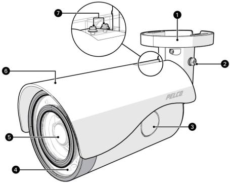
Product Overview
Next Gen IBE Series Bullet Camera
(1)Mounting Base: Use the mounting base to surface mount the camera or mount with one of the optional mounting accessories (pole mount or wall mount).
(2)Set Screws: One of two set screws to secure after aiming the camera.
(3)SD Card Access: Onboard micro SD card storage up to 128 GB.
(4)Infrared and Camera Status LEDs: The Next Gen IBE Series Bullet Camera includes adaptive IR illumination up to 30 meters. There are LED lights in a circle along the outer edge of the camera.
The Next Gen IBE Series Bullet Camera also includes a Camera Status LED which appears red at power on, changes to flashing green through boot up, and then it turns off when the camera is in normal operation.
(5)Camera Lens: Built-in, varifocal, 3-9 mm or 9-22 mm lens.
(6)Sun Shield: Plastic sun shield shades light while helping with heat control.
(7)Screws: Two screws to fix the sun shield after adjustment.
9
 Loading...