


 Loading...
FD5 Series 650 TV lines
Ruggedized/Outdoor Dome Camera Installation/Operation Manual 18 to 32 VAC (Revision A)
EN_C3970M (05/14)
Before attempting to connect or operate this product, please read these instructions carefully and save this manual for future use.
FD5 series model names:
FD5-V9-6(X)
FD5-DV10-6(X)
FD5-IRV10-6(X)
FD5-DWV10-6(X)
FD5-DWV22-6(X)
1

|
CONTENTS |
|
|
CONTENTS |
|
Important Safety Instructions ................................................................................................................................... |
4 |
|
REGULATORY NOTICES [FCC CLASS B]........................................................................................................... |
5 |
|
Warranty.............................................................................................................................................................. |
6 |
|
1. Introduction............................................................................................................................................................. |
7 |
|
1.1 |
Before You Begin........................................................................................................................................ |
7 |
1.2 |
Package Contents....................................................................................................................................... |
7 |
1.3 |
Optional Accessories.................................................................................................................................. |
7 |
1.4 |
Dimensions .................................................................................................................................................. |
7 |
1.5 |
Names of Camera Parts............................................................................................................................. |
8 |
1.6 |
Routine Maintenance.................................................................................................................................. |
8 |
2. Installation .............................................................................................................................................................. |
9 |
|
2.1 |
Disassembling the Camera ....................................................................................................................... |
9 |
2.2 |
Installing the Waterproof Plug ................................................................................................................. |
10 |
2.3 |
Connecting the Wiring.............................................................................................................................. |
10 |
2.4 |
Mounting the Camera............................................................................................................................... |
10 |
2.5 |
Optional Camera Settings........................................................................................................................ |
13 |
2.6 Adjusting the Camera Position................................................................................................................ |
14 |
|
2.7 Adjusting the Lens (if equipped with vari-focal lens)............................................................................ |
14 |
|
2.8 |
Completing the Installation ...................................................................................................................... |
15 |
2.9 |
General Help for Waterproof Plug Installation ...................................................................................... |
16 |
3. OSD Menu............................................................................................................................................................ |
18 |
|
4. OSD Menu Settings ............................................................................................................................................ |
20 |
|
4.1(A) LENS...................................................................................................................................................... |
21 |
|
4.2(A) SHUTTER/AGC ................................................................................................................................... |
21 |
|
4.3(A) WHITE BAL .......................................................................................................................................... |
22 |
|
4.4(A) BACKLIGHT ......................................................................................................................................... |
23 |
|
4.5(A) PICTURE ADJUST.............................................................................................................................. |
23 |
|
4.6(A) ATR* ...................................................................................................................................................... |
23 |
|
4.7(A) MOTION DET....................................................................................................................................... |
24 |
|
4.8(A) PRIVACY .............................................................................................................................................. |
24 |
|
4.9(A) DAY/NIGHT .......................................................................................................................................... |
25 |
|
4.10(A) NR........................................................................................................................................................ |
25 |
|
4.11(A) CAMERA ID........................................................................................................................................ |
26 |
|
4.12(A) SYNC................................................................................................................................................... |
26 |
|
4.13(A) LANGUAGE........................................................................................................................................ |
26 |
|
4.14(A) CAMERA RESET .............................................................................................................................. |
26 |
|
4.15(A) SAVE ALL........................................................................................................................................... |
26 |
|
4.1(B) LENS....................................................................................................................................................... |
27 |
|
4.2(B) SHUTTER/AGC ................................................................................................................................... |
28 |
|
4.3(B) WHITE BAL .......................................................................................................................................... |
29 |
|
4.4(B) HLC/BLC ............................................................................................................................................... |
30 |
|
4.5(B) PICTURE ADJUST.............................................................................................................................. |
31 |
|
4.6(B) WDR ...................................................................................................................................................... |
31 |
|
4.7(B) MOTION DET....................................................................................................................................... |
32 |
|
4.8(B) PRIVACY .............................................................................................................................................. |
32 |
|
4.9(B) DAY/NIGHT .......................................................................................................................................... |
32 |
|
4.10(B) 3D NR.................................................................................................................................................. |
33 |
|
4.11(B) CAMERA ID........................................................................................................................................ |
33 |
|
4.12(B) SYNC................................................................................................................................................... |
33 |
|
4.13(B) LANGUAGE........................................................................................................................................ |
33 |
|
4.14(B) CAMERA RESET .............................................................................................................................. |
33 |
|
4.15(B) EZOOM ............................................................................................................................................... |
33 |
|
4.16(B) DIS ....................................................................................................................................................... |
34 |
|
4.17(B) FOCUS ADJ ....................................................................................................................................... |
34 |
|
4.18(B) ALARM................................................................................................................................................ |
34 |
|
|
|
2 |
EN_C3970M (05/14)

|
CONTENTS |
|
|
CONTENTS |
|
4.19(B) REMOTE............................................................................................................................................. |
|
35 |
4.20(B) SAVE ALL........................................................................................................................................... |
|
35 |
5. Specifications....................................................................................................................................................... |
|
36 |
Pelco Troubleshooting Contact Information......................................................................................................... |
|
41 |
Note for Dimension Drawings................................................................................................................................ |
|
41 |
3
EN_C3970M (05/14)

Important Notices
Important Safety Instructions
1.Read these instructions.
2.Keep these instructions.
3.Heed all warnings.
4.Follow all instructions.
5.Clean only with dry cloth.
6.Do not block any ventilation openings. Install in accordance with the manufacturer’s instructions.
7.Do not install near any heat sources such as radiators, heat registers, stoves, or other apparatus (including amplifiers) that produce heat.
8.Protect the power cord from being walked on or pinched particularly at plugs, convenience receptacles, and the points where they exit from the apparatus.
9.Only use attachments/accessories specified by the manufacturer.
10.Use only with the cart, stand, tripod, bracket, or table specified by the manufacturer, or sold with the apparatus. When a cart is used, use caution when moving the cart/apparatus combination to avoid injury from tip-over.
11.Refer all servicing to qualified service personnel. Servicing is required when the apparatus has been damaged in any way, such as power-supply cord or plug is damaged, liquid has been spilled or objects have fallen into the apparatus, the apparatus has been exposed to rain or moisture, does not operate normally, or has been dropped.
12.WARNING: To reduce the risk of fire or electric shock, do not expose this apparatus to rain or moisture.
13.Installation should be done only by qualified personnel and conform to all local codes.
14.Unless the unit is specifically marked as a NEMA Type 3, 3R, 3S, 4, 4X, 6, or 6P enclosure, it is designed for indoor use only and it must not be installed where exposed to rain and moisture.
15.Use only installation methods and materials capable of supporting four times the maximum specified load.
16.Use stainless steel hardware to fasten the mount to outdoor surfaces.
17.To prevent damage from water leakage when installing a mount outdoors on a roof or wall, apply sealant around the bolt holes between the mount and mounting surface.
18.An all-pole mains switch with a contact separation of at least 3 mm in each pole shall be incorporated in the electrical installation of the building.
19.A readily accessible disconnect device shall be incorporated in the building installation wiring.
20.The socket-outlet shall be installed near the equipment and shall be easily accessible.
4
EN_C3970M (05/14)

Important Notices
CAUTION: These servicing instructions are for use by qualified service personnel only. To reduce the risk of electric shock do not perform any servicing other that contained in the operating instructions unless you are qualified to do so.
CAUTION: Danger of explosion if battery is incorrectly replaced. Replace only with the same or equivalent type. Dispose of used batteries according to the instructions provided by the battery manufacturer.
Only use replacement parts recommended by Pelco.
The product and/or manual may bear the following marks:
This symbol indicates that dangerous voltage constituting a risk of electric shock is present within this unit.
CAUTION: RISK OF ELECTRIC SHOCK. DO NOT OPEN.
This symbol indicates that there are important operating and maintenance instructions in the literature accompanying this unit
WARNING: This product is sensitive to Electrostatic Discharge (ESD). To avoid ESD damage to this product, use
ESD safe practices during installation. Before touching, adjusting or handling this product, correctly attach an ESD wrist strap to your wrist and appropriately discharge your body and tools. For more information about ESD control and safe handling practices of electronics, please refer to ANSI/ESD S20.20-1999 or contact the Electrostatic Discharge Association (www.esda.org).
REGULATORY NOTICES [FCC CLASS B]
This device complies with Part 15 of the FCC Rules. Operation is subject to the following two conditions: (1) this device may not cause harmful interference, and (2) this device must accept any interference received, including interference that may cause undesired operation.
RADIO AND TELEVISION INTERFERENCE
This equipment has been tested and found to comply with the limits of a Class B digital device, pursuant to Part 15 of the FCC Rules. These limits are designed to provide reasonable protection against harmful interference in a residential installation. This equipment generates, uses, and can radiate radio frequency energy and, if not installed and used in accordance with the instructions, may cause harmful interference to radio communications. However there is no guarantee that the interference will not occur in a particular installation. If this equipment does cause harmful interference to radio or television reception, which can be determined by turning the equipment off and on, the user is encouraged to try to correct the interference by one or more of the following measures:
•Reorient or relocate the receiving antenna.
•Increase the separation between the equipment and the receiver.
•Connect the equipment into an outlet on a circuit different from that to which the receiver is connected.
•Consult the dealer or an experienced radio/TV technician for help.
You may also find helpful the following booklet, prepared by the FCC: “How to Identify and Resolve Radio-TV Interference Problems.” This booklet is available from the U.S. Government Printing Office, Washington D.C. 20402.
Changes and Modifications not expressly approved by the manufacturer or registrant of this equipment can void your authority to operate this equipment under Federal Communications Commission’s rules.
This Class B digital apparatus complies with Canadian ICES-003.
Cet appareil numérique de la classe B est conforme à la norme NMB-003 du Canada.
5
EN_C3970M (05/14)

Important Notices
Warranty
For information about Pelco’s product warranty and thereto related information, refer to www.pelco.com/warranty.
Operating Notes:
Warning:
For FD5 camera 18 to 32 VAC (Revision A); released in 2014,
•Connect to 12 VDC or 18 to 32 VAC power adapter For older FD5 cameras (Prior to Revision A)
•Connect to 12 VDC or 24 VAC power adapter.
Operating Conditions
•Avoid viewing very bright objects (for example, light fixtures) for extended periods.
•Avoid operating or storing the unit in the following locations:
-Extremely humid, dusty, hot/cold environments where the operating temperature is outside the recommended range.
-Close to sources of powerful radio or TV transmitters
-Close to fluorescent lamps or objects reflecting light
-Under unstable light sources (may cause flickering)
Suggested Installation:
-For outdoor environmental conditions from -30°C to +50°C (-22°F to 122°F), use only an AC power supply source (18 to 32VAC)
-For indoor or outdoor applications with ambient temperatures of 0°C to +50°C (32°F to 122°F), use 12VDC power, or an AC power supply source (18 to 32VAC)
6
EN_C3970M (05/14)
Introduction
1. Introduction
The dome camera series are ideal for outdoor installation in a commercial environment. With 3-axis mount support, it provides flexible installation on a ceiling or wall even at an angle.
1.1 Before You Begin
Please read this guide carefully before you install the dome camera. Keep this guide for future reference.
1.2 Package Contents
Check that the items received match those listed on the order form and packing slip. The dome camera series packing box includes:
•One fully assembled camera
•Four screw anchors and TP4x25mm tapping screws
•Four M4x15mm screws
•One guide pattern
•One user manual
•One waterproof plug
•One T20 wrench
If any parts are missing or damaged, contact the dealer you purchased the camera from.
1.3 Optional Accessories
• FD-SC service cable
We recommend you connect a local viewing monitor via the optional FD-SC service cable for setup.
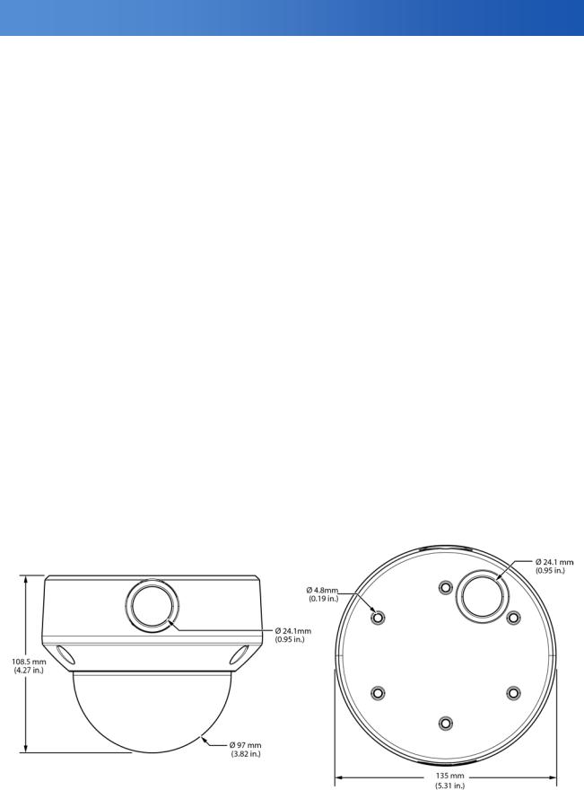
1.4 Dimensions
7
EN_C3970M (05/14)

Introduction
1.5 Names of Camera Parts
Figure 1-1 FD5-V9-6(X) |
Figure1-2 FD5-DV10-6(X) |
Figure1-3 FD5-IRV10-6(X) |
Figure1-4 FD5-DWV10-6(X) |
|
FD5-DWV22-6(X) |
A.Video output connector
B.18 to 32 VAC /12 VDC power Input connector (Red +/Black -)
C.Alarm Out: Connect to device that responds to alarm signals (Blue+/Brown-).
Note: See Figure 2-7 for camera setup controls.
1.6 Routine Maintenance
•The dome cover is an optical part. Use a soft, dry cloth to remove any fingerprints or dust.
•Clean the camera housing with a soft, dry cloth. For more stubborn stains, use a cloth dampened with a small quantity of neutral detergent, then wipe dry.
Caution: Do not use volatile solvents such as alcohol, benzene or thinners to avoid damaging the surface finish.
8
EN_C3970M (05/14)
Installation
2. Installation
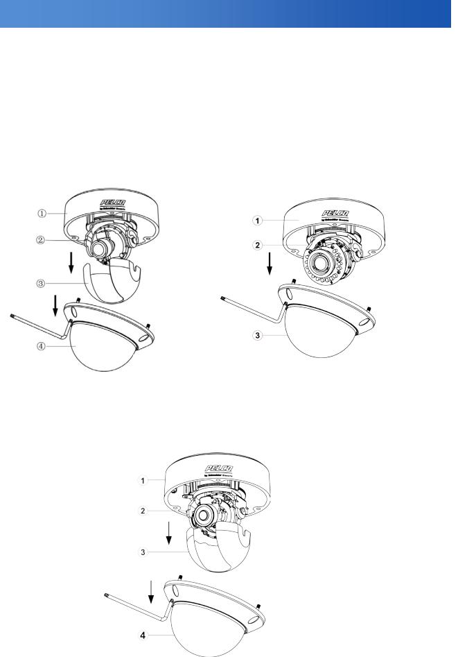
2.1 Disassembling the Camera
Before you mount and adjust the camera, follow these steps to disassemble the camera.
1.Loosen the installed torx screws and remove them.
2.Remove the inner liner by gently pulling it free from the tilt adjustment bracket. For the models without inner liner, please simply skip this step.
3.Set the dome cover (and liner) aside.
1. |
Bottom case |
1. Bottom case |
|
2. |
Tilt adjustment bracket |
||
2. Tilt adjustment bracket |
|||
3. |
Inner liner |
||
3. Dome cover |
|||
4. |
Dome cover |
||
|
FD5-V9-6(X)/FD5-DV10-6(X) FD5-IRV10-6(X)
FD5-DWV10-6(X)
FD5-DWV22-6(X)
1. Bottom case
2. Tilt adjustment bracket
3. Inner liner
4. Dome cover
Figure 2-1 Disassemble the Camera
9
EN_C3970M (05/14)
Installation
2.2 Installing the Waterproof Plug
Plug the waterproof plug into the side conduit hole, or bottom conduit hole if side conduit hole is used for wiring. See “2.9 General help for installing waterproof plug” for more information.
Figure 2-2 Waterproof Plug Installation
2.3 Connecting the Wiring
Refer to Figure 1-1/1-2/1-3/1-4 to connect the video connect output connector (A) and 24 VAC/18 to 32 VDC power connector (B).
Caution: For DC power supply use, make sure the polarity is correct to avoid malfunction and / or camera damage.
Note: When powering camera using 12VDC, we recommend that the camera is installed with a separate, isolated power supply to minimize power-related video interference.
2.4 Mounting the Camera
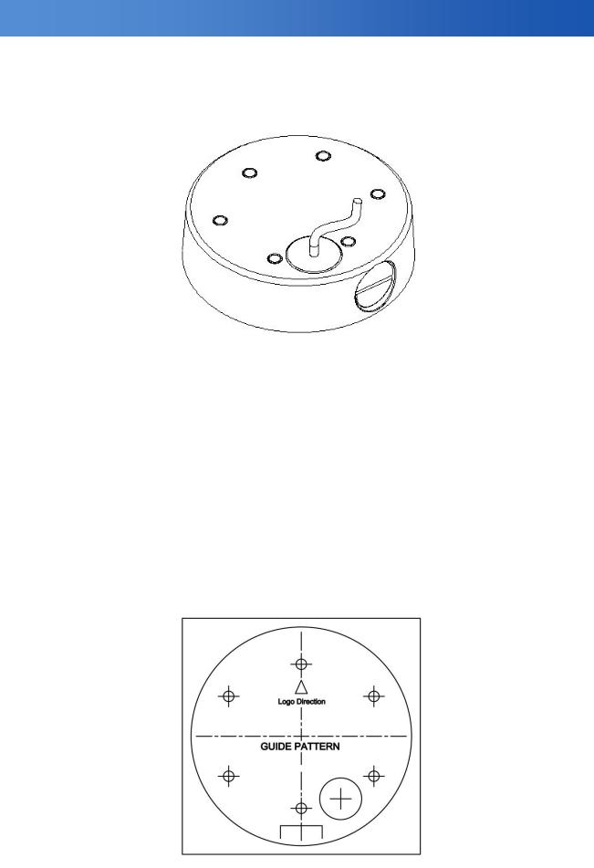
1. Attach the mounting template to the wall or ceiling.
Figure 2-3
10
EN_C3970M (05/14)
Installation
2.Before mounting the dome on a ceiling or a wall, please designate two screw holes or four screw holes and pull out the corresponding outer rubber plugs by using tools like a screwdriver, etc.
Note: With four screw anchors and TP4x25mm tapping screws provided, you can choose two-hole installation (refer to Figure 2-4) or change to four-hole installation (refer to Figure 2-5) when mounting the camera on a ceiling or wall. This manual describes two-hole installation only.
Figure 2-4
Figure 2-5
Note: Don’t pull out the other rubber plugs to keep the IP66 performance of the camera. Also, never remove the inside rubber plugs. Always install mounting screw through the inside plug.
11
EN_C3970M (05/14)
Installation
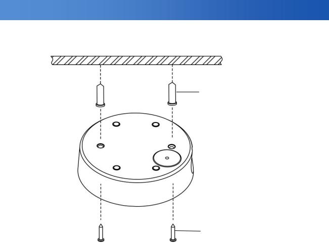
3.Drill two holes, and then insert the screw anchors (#1) into the holes.
4.Secure the bottom case to the wall or ceiling with the TP4 x 25 mm tapping screws supplied (#2).
1. Screw anchors (x4), supplied
2. TP4 x 25mm tapping screws (x4), supplied
Figure 2-6 (typical)
Note: Depending on the material of your mounting surface, you may require different screws and anchors than those supplied. Use caution to maintain a water tight seal to the mounting hardware.
12
EN_C3970M (05/14)
Installation
2.5 Optional Camera Settings
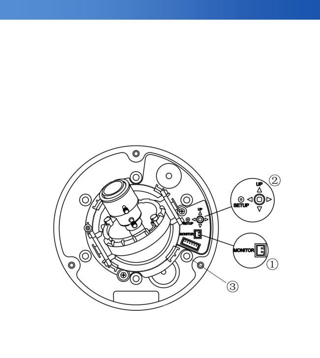
Refer to Figure 2-7 to locate the OSD joystick control on the camera board. Use the joystick to access the OSD menu and configure the camera settings as required.
To use the OSD joystick control:
•Press the OSD joystick control straight down to enter the Main menu or a selected item.
•Move the OSD joystick control UP, DOWN, LEFT and RIGHT to navigate through menus and options. For further information on OSD settings, refer to the “4.OSD Settings” section.
Note: Connect a local viewing monitor via the optional FD-SC service cable for setup.
1. Monitor out
2. OSD Joystick Control
3. Camera mounting holes
Figure 2-7 Camera Adjustment Controls
13
EN_C3970M (05/14)
Installation
2.6 Adjusting the Camera Position
The dome camera has three axes for positioning the camera. While monitoring the picture on the monitor, adjust the camera position as follows:
•Pan Adjustment: Rotate 3D assembly in the base. Do not turn assembly more than 360° as this may cause the internal cables to twist and disconnect or break.
•Tilt Adjustment: After loosening the screw on the bracket, position the camera as desired, and then tighten the screw back to the bracket.
•Horizontal Rotation: For wall mount and tilted ceilings, rotate the lens base (maximum 360°) until you are satisfied with the field of view.
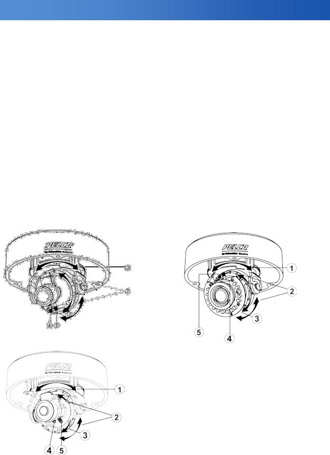
2.7 Adjusting the Lens (if equipped with vari-focal lens)
1.Loosen the zoom lever (#4) counter-clockwise a little, and then rotate the zoom lever and determine the image view.
2.Loosen the focus lever (#5) counter-clockwise a little, and then adjust the focus for optimum picture sharpness.
3.Re-tighten the zoom lever and focus lever after adjustment.
Note: It is important that you lock the zoom and focus levers after making adjustments. This will avoid the positions moving (for example, from temperature changes or vibrations).
FD5-V9-6(X)/FD5-DV10-6(X) |
FD5-IRV10-6(X) |
|
|
Instructions for the Figure 2-8 Camera adjustment:
1.Rotate 3D assembly in base for horizontal adjustment
2.Tilt adjustment bracket and screw for vertical adjustment
3.Axis ring for horizontal rotation on wall mount / tilted ceilings
4.Zoom lever
5.Focus lever
FD5-DWV10-6(X)
FD5-DWV22-6(X)
Figure 2-8 Camera Adjustment
14
EN_C3970M (05/14)
Loading...