


® |
CM6700 Matrix |
Switcher/Controller |
Installation/ |
Operation Manual |
C523M-H (6/05) |
Pelco • 3500 Pelco Way • Clovis, CA 93612-5699 USA • www.pelco.com |
In North America and Canada: Tel (800) 289-9100 • FAX (800) 289-9150 |
International Customers: Tel +1(559) 292-1981 • FAX +1(559) 348-1120 |

CONTENTS |
|
|
Section |
Page |
|
IMPORTANT SAFEGUARDS AND WARNINGS ................................................................ |
3 |
|
MODELS ............................................................................................................................ |
4 |
|
|
ASSOCIATED EQUIPMENT ...................................................................................... |
4 |
DESCRIPTION ................................................................................................................... |
5 |
|
INSTALLATION .................................................................................................................. |
8 |
|
|
SET OPTIONS ........................................................................................................... |
8 |
|
MOUNT UNIT ............................................................................................................. |
9 |
|
CONNECT VIDEO SOURCES ................................................................................. |
10 |
|
CONNECT CONTROL LINES ................................................................................... |
11 |
|
CONNECT MONITORS ............................................................................................ |
13 |
|
CONNECT ALARMS ................................................................................................. |
14 |
|
CONNECT AUXILIARIES ......................................................................................... |
15 |
|
CONNECT COM 2 PORT ......................................................................................... |
17 |
|
CONNECT KEYBOARDS ......................................................................................... |
18 |
PROGRAMMING .............................................................................................................. |
20 |
|
OPERATION ..................................................................................................................... |
36 |
|
|
ASCII OPERATING COMMANDS ............................................................................ |
36 |
TROUBLESHOOTING ...................................................................................................... |
39 |
|
|
GAINING INITIAL CONTROL ................................................................................... |
39 |
|
USING A PC TO SEND ASCII COMMANDS VIA COM 2 ......................................... |
39 |
|
PERFORMING A SOFTWARE RESET ..................................................................... |
39 |
SPECIFICATIONS ............................................................................................................. |
41 |
|
INDEX ............................................................................................................................... |
43 |
|
|
REGULATORY NOTICES ......................................................................................... |
44 |
WARRANTY AND RETURN INFORMATION .................................................................... |
44 |
|
LIST OF ILLUSTRATIONS |
|
|
Figure |
Page |
|
1 |
CM6700 Applications ......................................................................................... |
6 |
2 |
Application with a Multiplexer ............................................................................. |
7 |
3 |
Applications with Remote Keyboards (ASCII, KBD200A Only) .......................... |
7 |
4 |
Cover Removal .................................................................................................. |
8 |
5 |
Video Termination Jumpers ................................................................................ |
8 |
6 |
DIP Switch Locations ......................................................................................... |
9 |
7 |
Installing Mounting Ears ..................................................................................... |
9 |
8 |
Mounting the Matrix Switcher ............................................................................ |
10 |
9 |
Connecting Video Sources ................................................................................ |
10 |
11 |
Daisy-Chaining Receivers ................................................................................. |
11 |
10 |
COM 1 Connections on the SCU ...................................................................... |
11 |
12 |
Making Receiver Connections at a Distribution Block (CM9760-CDU-T) ......... |
12 |
13 |
Monitor Connections ......................................................................................... |
13 |
14 |
Connecting Alarms ............................................................................................ |
14 |
15 |
Wiring the AUX 1 (Relay) Output ...................................................................... |
15 |
16 |
Wiring the AUX 2 and AUX 3 (TTL) Outputs ..................................................... |
16 |
17 |
Connecting an RS-232 Interface ....................................................................... |
17 |
18 |
Connecting an RS-422/485 Interface ................................................................ |
17 |
19 |
Installing Local and Remote Keyboards ........................................................... |
18 |
20 |
Quick Reference Chart ..................................................................................... |
21 |
21 |
Software Reset Button Location ....................................................................... |
39 |
LIST OF TABLES |
|
|
Table |
Page |
|
A |
Keyboard Addresses ......................................................................................... |
19 |
B |
Programming the CM6700 Switching Control Unit ........................................... |
20 |
C |
Examples of ASCII Commands ......................................................................... |
36 |
D |
ASCII Commands ............................................................................................. |
37 |
E |
Solutions To Common Problems ....................................................................... |
40 |
F |
Switcher/Controller and Keyboard RJ-45 Pin Functions ................................... |
40 |
2 |
Pelco Manual C523M-H (6/05) |
IMPORTANT SAFEGUARDS AND WARNINGS
Prior to installation and use of this product, the following WARNINGS should be observed.
1.Installation and servicing should be done only by qualified service personnel and conform to all local codes.
2.This unit is designed for indoor use only and must not be installed where exposed to rain and moisture.
3.The installation method and materials should be capable of supporting four times the weight of the unit and equipment.
4.After replacement/repair of this unit’s electrical components, conduct a resistance measurement between line and exposed parts to verify the exposed parts have not been connected to line circuitry.
The product and/or manual may bear the following marks:
This symbol indicates that dangerous voltage constituting a risk of electric shock is present within this unit.
This symbol indicates that there are important operating and maintenance instructions in the literature accompanying this unit.
C A U T I O N :
RISK OF ELECTRIC SHOCK.
DO NOT OPEN.
Please thoroughly familiarize yourself with the information in this manual prior to installation and operation.
REGULATORY NOTICES
This equipment has been tested and found to comply with the limits of a Class A digital device, pursuant to part 15 of the FCC rules. These limits are designed to provide reasonable protection against harmful interference when the equipment is operated in a commercial environment. This equipment generates, uses, and can radiate radio frequency energy and, if not installed and used in accordance with the instruction manual, may cause harmful interference to radio communications. Operation of this equipment in a residential area is likely to cause harmful interference in which case the user will be required to correct the interference at his own expense.
Pelco Manual C523M-H (6/05) |
3 |

MODELS
CM6700-MXB2 |
Matrix switcher/controller with 16 video inputs and 2 monitor outputs, |
|
120 VAC, 50/60 Hz |
CM6700-MXB2-X Same as CM6700-MXB2, PAL-configured for 230 VAC and 50 Hz
|
operation |
CM6700-MXB4 |
Same as CM6700-MXB2 with two-monitor expansion card |
|
(CM6700VMC2) pre-installed |
CM6700-MXB4-X Same as CM6700-MXB4, PAL-configured for 230 VAC and 50 Hz operation
ASSOCIATED EQUIPMENT
KBD100 |
Desktop keyboard with full switching and programming capabilities |
KBD200A |
Desktop keyboard with full switching and programming capabilities, |
|
plus push-button control of PTZ functions |
KBD300A |
Desktop keyboard with full switching and programming capabilities, |
|
plus joystick control of PTZ functions |
CM6700-VMC2 |
Expansion card with two monitor outputs |
CM6700-VMC2-X Expansion card with two monitor outputs, PAL-configured |
|
KBDKIT |
Wiring kit for connecting KBD100, KBD200A, and KBD300A keyboards |
|
to remote keyboard port; includes two RJ-45 wall blocks and a trans- |
|
former to convert 120 VAC to 12 VAC for keyboard power |
KBDKIT-X |
Wiring kit for connecting KBD100, KBD200A, and KBD300A keyboards |
|
to remote keyboard port; includes two RJ-45 wall blocks and a trans- |
|
former to convert 230 VAC to 12 VAC for keyboard power |
CM9760-CDU-T This is a 16-channel RS-422 transmit-only (two-wire and ground) distributor that is used primarily to install pan and tilt and dome receivers in a star configuration.
4 |
Pelco Manual C523M-H (6/05) |

DESCRIPTION
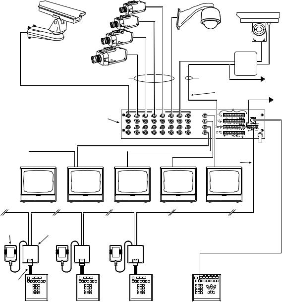
Pelco’s CM6700 is a keyboard-controlled cross-point video matrix switcher/control unit (SCU) that allows you to route up to sixteen video images to as many as four monitors while controlling camera positions.
Applications
The CM6700 SCU can be controlled from a local or remote keyboard (refer to Figure 1), used with a multiplexer to display multiple camera views on a monitor (refer to Figure 2), and interfaced to a distant keyboard via dial-up telephone circuits through appropriate interface equipment (refer to Figure 3). The CM6700 features menu-driven, password-protected programming. The CM6700 can also be controlled from a personal computer using ASCII commands.
Keyboards
Camera positioning options can be programmed and controlled from a keyboard. Up to eight keyboards can be connected to the CM6700 SCU, allowing monitoring stations that share a common monitor to each have a keyboard. Four different keyboards are available to use with the CM6700 SCU, each with varying features and different costs. (Keyboard types can be mixed in a system – See Associated Equipment.)
Sequences, Presets, and Patterns
Special programmed operations include sequences, presets and patterns.
A sequence allows you to see a routine of 16 camera views on your monitor over and over again. The sequence can be operated automatically or manually. The order in which the views appear and the time each view remains can be programmed.
A preset allows you to direct a pan/tilt/zoom (camera positioning system) to move to a certain position on command or as a result of an alarm. In addition to moving the camera, a descriptive title can appear on the screen. (Presets are not available with the
KBD100 keyboard.)
With a pattern you can program a camera positioning system to move around its viewing area in a repeating pattern. The number and time length of patterns varies with different positioning systems. (Patterns are not available with the KBD100 keyboard.)
Alarm Inputs
Eighteen alarm inputs are provided. These can be programmed to cause the display to switch automatically to the camera with the alarm and/or to operate one of three auxiliary outputs. Sixteen of the inputs are associated with individual cameras. Two of the inputs activate group camera sequences.
Auxiliary Outputs
Three auxiliary outputs are provided. One output is a relay and two are open collector (TTL) outputs. Auxiliary outputs are activated at the keyboard (except KBD100).
Protocols
The CM6700 works with Pelco’s Coaxitron®‚ D, and P protocol receivers.
Power, Mounting Methods
The CM6700 SCU operates on 120 VAC or 230 VAC, depending on the model. The compact case mounts in 3-1/2 inches of vertical space in a 19-inch equipment bay or to a wall or table top.
Pelco Manual C523M-H (6/05) |
5 |
|
COAXITRON |
|
|
|
|
|
|
|
|
|
|
|
|
|
|
|
|
|
|
RCVR |
|
|
|
|
|
|
|
|
|
|
SHIELDED |
DAISY-CHAIN TO |
|
COAXITRON |
|
|
|
|
|
|
TWISTED |
OTHER |
|
|
|
|
|
|
|
|
|
|
PAIR |
RECEIVERS |
|
|
|
|
|
|
|
|
|
RS-422 (P OR D) |
|
|
|
|
|
|
|
|
|
|
|
RS-232 TO PC OR |
|
|
|
|
|
|
|
|
|
TO ALARM |
CARD ACCESS |
|
|
|
|
|
|
|
|
|
CONTACTS |
COMPUTER |
|
|
|
|
|
|
VIDEO INPUTS |
|
|
VIDEO OUTPUTS |
|
|
|
|
|
|
|
|
|
|
|
LOCAL |
|
CM6700 SCU |
|
|
|
|
|
|
|
1 |
KEYBOARD |
|
1 |
3 |
5 |
7 |
9 |
1 |
13 |
15 |
|
|
|
|
|
|
|
|
|
|
|
2 |
|
|
|
|
|
|
|
|
|
|
3 |
|
|
|
2 |
4 |
6 |
8 |
10 |
12 |
14 |
16 |
|
|
|
|
|
|
|
|
|
|
4 |
|
|
|
|
|
|
|
|
|
|
RS-485 |
|
12 VAC |
|
|
|
|
|
|
|
|
|
|
TRANSFORMER |
WALL BLOCK |
|
|
|
|
|
|
|
|
|
DATA |
|
|
|
|
|
|
|
|
|
|
CABLE |
|
|
|
|
|
|
|
|
|
|
|
|
|
|
|
|
KBD100/200A/300A |
|
|||
|
REMOTE KEYBOARDS |
|
|
|
|
|
|
LOCAL KEYBOARD |
00044 |
|
|
|
|
|
|
|
|
|
|||
Figure 1. CM6700 Applications
6 |
Pelco Manual C523M-H (6/05) |

CAMERA VIDEO
|
|
|
|
|
MULTIPLEXER |
|
||
|
|
|
|
|
|
|
MULTIPLEXED |
|
LOOPED VIDEO INPUTS |
|
|
VIDEO |
|
||||
|
|
|
|
|||||
|
|
|
|
VIDEO INPUTS |
|
* |
VIDEO OUTPUTS |
|
|
|
|
|
|
|
LOCAL |
||
|
|
|
|
|
|
|
|
|
|
|
|
|
|
|
|
1 |
KEYBOARD |
1 |
3 |
5 |
7 |
9 |
11 |
13 |
15 |
|
|
|
|
|
|
|
|
2 |
|
|
|
|
|
|
|
|
3 |
|
2 |
4 |
6 |
8 |
10 |
12 |
14 |
16 |
|
|
|
|
|
|
|
|
4 |
|
|
|
|
CM6700 SCU |
* |
|
|||
|
|
|
|
|
|
|
|
|
MULTIPLEXER |
|
|
|
|
|
|
|
|
*ALTERNATE MULTIPLEXED
VIDEO ROUTING THROUGH A CAMERA INPUT.
KBD200A/300A |
00045 |
Figure 2. Application with a Multiplexer
VIDEO INPUTS |
VIDEO OUTPUTS |
LOCAL
1 |
KEYBOARD |
1 |
3 |
5 |
7 |
9 |
1 |
13 |
15 |
|
|
|
|
|
|
|
|
|
|
|
2 |
|
|
|
|
|
|
|
|
|
|
3 |
|
|
2 |
4 |
6 |
8 |
10 |
12 |
14 |
16 |
|
|
|
|
|
|
|
|
|
|
|
4 |
|
|
|
|
|
|
|
|
|
|
RS-422 FACILITY (FIBER OPTIC TERMINAL, |
KBD200A |
|
|
|
|
|
|
|
|
|
ETC.) TO REMOTE KEYBOARD (ASCII) |
|
|
NOTE: ASCII DOES |
|
|
CONTROL |
|
||||||
|
|
NOT SUPPORT |
|
|
|
|
||||
|
|
PROGRAMMING |
|
FOT |
FOT |
|
||||
|
|
|
|
|
|
|
|
|
||
FOT = FIBER OPTIC TERMINAL |
(VIDEO+) |
(VIDEO+) |
|
|||||||
|
|
|
|
|
|
|
|
VIDEO |
|
MONITOR |
|
|
|
|
|
|
|
|
|
|
|
|
|
|
|
|
|
|
|
RS-232 FACILITY (PELCOVISION, ETC.) |
|
|
|
|
|
|
|
|
|
|
TO REMOTE KEYBOARD (ASCII) |
|
|
|
|
|
|
|
|
|
|
|
CONTROL |
|
|
|
|
|
|
|
|
|
|
|
KBD200A |
|
|
|
|
|
|
|
|
TRANSMITTER |
RECEIVER |
|
PSTN
VIDEO
00046
MONITOR
Figure 3. Applications with Remote Keyboards (ASCII, KBD200A Only)
Pelco Manual C523M-H (6/05) |
7 |
INSTALLATION
1SET OPTIONS
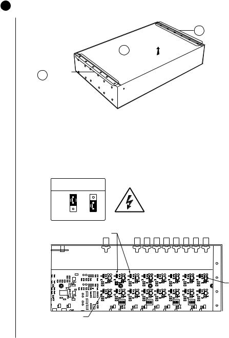
1.Refer to Figure 4. Remove the cover.
B REMOVESCREWS 6
C LIFTOFF COVER 
A REMOVESCREWS 6
00055
Figure 4. Cover Removal
2.Refer to Figure 5. Set jumpers according to your system requirements. JP1-JP16 are used to terminate the video input with a 75-ohm resistor or to unterminate the video (looping). The factory default has the jumper installed in the terminating position. If you are connecting only a camera to an input, leave the jumper in the terminating position.
If you are looping the video to another device, move the jumper to the looped position, and terminate at the equipment connected to the looping output.
75-OHM TERMINATION
JUMPER
KEY
TERMINATED LOOPED
75-OHM TERMINATION |
BACK OF SCU |
|
JUMPERS (ONE PER INPUT) |
||
|
|
|
|
|
|
|
|
|
|
|
|
|
|
|
|
JP1 |
ON |
|
|
|
ON |
|
|
|
ON |
|
|
|
ON |
|
|
|
1 |
2 |
3 |
4 |
1 |
2 |
3 |
4 |
1 |
2 |
3 |
4 |
1 |
2 |
3 |
4 |
JP16
NOTE: JUMPER JP1 CORRESPONDS TO VIDEO INPUT 1,
JP2 TO VIDEO INPUT 2, ETC.
Figure 5. Video Termination Jumpers
8 |
Pelco Manual C523M-H (6/05) |
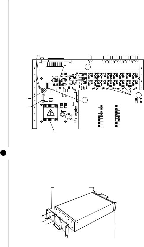
3.Refer to Figure 6. Set DIP switches.
a.Communication port 2 is available for a PC or remote keyboard operating in ASCII mode. (Refer to ASCII Operating Commands.) Most PC applications require
RS-232. A remote keyboard can require either RS-232 or RS-422, depending on the communications facility. To find out the required interface, check your PC serial port information or refer to your keyboard manual. Set DIP switch SW5 (COM 2) for RS-232 or RS-422, according to your system requirements. The
SCU is configured at the factory for RS-422.
b.DIP switches SW1, SW2, SW3 and SW4 are to remain in the factory default position (OFF).
c.DIP switch SW6 (COM1) is to remain in factory default position (RS-422).
|
|
|
SW6 DEFAULTS |
3c |
|
|
|
|
|
|
|
|
|
|
|
|
|
|
|
|
|
|
|
|
|
|
TO RS-422 |
|
|
|
|
|
|
|
|
|
|
|
|
|
|
|
|
|
|
|
|
|
|
1 |
ON |
|
|
|
|
|
|
|
|
|
|
|
|
|
|
|
|
|
|
|
|
|
|
2 |
|
|
|
|
|
|
|
|
|
|
|
|
|
|
|
|
|
|
|
|
|
|
|
3 |
|
|
|
|
|
|
|
|
|
|
|
|
|
|
|
|
|
|
|
|
|
|
|
4 |
|
|
|
|
|
|
|
|
|
|
|
|
|
|
|
|
|
|
|
|
|
1 |
ON |
5 |
|
|
|
|
|
|
|
|
|
|
|
|
|
|
|
|
|
|
|
|
|
2 |
|
6 |
|
|
|
|
|
|
|
|
|
|
|
|
|
|
|
|
|
|
|
|
|
3 |
|
7 |
|
|
|
|
|
|
|
|
|
|
|
|
|
|
|
|
|
|
|
|
|
4 |
|
8 |
|
|
|
ON |
|
|
|
ON |
|
|
|
|
ON |
|
|
|
ON |
|
|
|
|
5 |
|
|
|
|
|
|
|
|
|
|
|
|
|
|
|
|
|
|
|
|
|
|
|
6 |
|
|
|
|
|
1 |
2 |
3 |
4 |
1 |
2 |
3 |
4 |
|
1 |
2 |
3 |
4 |
1 |
2 |
3 |
4 |
|
7 |
|
|
|
|
|
|
|
||||||||||||||||
8 |
|
|
|
|
|
|
|
|
|
|
|
|
|
|
|
|
|
|
|
|
|
|
|
POWER |
|
|
|
|
|
SW5 & 6 DIP SWITCH SETTINGS |
|
|
|
3b |
|||||||||||||
TERMINAL |
|
|
|
3a |
|
|
|
|
|
||||||||||||||
BLOCK |
|
|
|
RS-422/485 |
|
|
|
RS-232 |
|
|
|
|
|
KEY |
|
||||||||
|
|
|
|
|
|
|
|
|
|
|
|
|
|
|
|
||||||||
FUSE |
|
|
|
|
|
1 |
|
|
|
ON |
|
|
|
1 |
ON |
|
|
|
|
|
ON |
OFF |
|
|
|
|
|
|
|
|
|
|
|
|
|
|
|
|
|
|
|
||||||
|
|
|
|
|
2 |
|
|
|
|
|
|
|
2 |
|
|
|
|
|
|
|
|
|
|
|
|
|
|
|
|
|
|
|
|
|
|
|
|
|
|
|
|
|
|
|
|
||
|
|
|
|
|
|
3 |
|
|
|
|
|
|
|
3 |
|
|
|
|
|
|
|
|
|
|
HIGH VOLTAGE |
|
|
|
|
4 |
|
|
|
|
|
|
|
4 |
|
|
|
|
|
|
|
|
|
|
|
|
|
|
5 |
|
|
|
|
|
|
|
5 |
|
|
|
|
|
|
|
|
|
|
|
|
|
|
|
|
|
|
|
|
|
|
|
|
|
|
|
|
|
|
|
|
||
|
|
|
|
|
|
6 |
|
|
|
|
|
|
|
6 |
|
|
|
|
|
|
|
|
|
|
|
|
|
|
|
7 |
|
|
|
|
|
|
|
7 |
|
|
|
|
|
|
|
|
|
|
|
|
|
|
|
8 |
|
|
|
|
|
|
|
8 |
|
|
|
|
|
|
|
|
|
|
|
TRANSFORMER |
|
|
|
|
|
|
|
|
|
|
|
|
|
|
|
|
|
|
|
00054 |
|
|
|
|
|
|
|
|
|
|
|
|
|
|
|
|
|
|
|
|
|
|
|
||
Figure 6. DIP Switch Locations
4.Replace cover.
2MOUNT UNIT
1.Select a suitable location for the SCU. It must be within 6 feet (1.8 m) of a suitable electrical outlet. Do not connect the power yet.
2.Refer to Figure 7. Position mounting ears on the sides of the SCU for the appropriate mounting. If the ears are not required, leave them off.
POSITION BRACKETS FOR
RACK MOUNTING (REAR)
 POSITION BRACKETS FOR
UNDER-TABLE MOUNTING
 NOTE: EACH SCU COMES WITH POSITION BRACKETS FOR
 2 MOUNTING BRACKETS FLUSH MOUNTING
(WALL OR TABLE TOP)
Figure 7. Installing Mounting Ears
Pelco Manual C523M-H (6/05) |
9 |
3.Refer to Figure 8. Use suitable hardware to mount the SCU an in equipment bay or against a flat surface, according to your installation requirements.
MOUNT TO RACK OR SURFACE
WITH 4 SCREWS
Figure 8. Mounting the Matrix Switcher
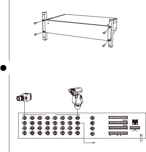
3 CONNECT VIDEO SOURCES
Refer to Figure 9. Connect video cables at the appropriate BNC receptacles on the back of the SCU.
CAMERA 15
CAMERA 1
CM6700 SCU
VIDEO INPUTS |
VIDEO OUTPUTS |
1 |
ALARMS |
LOCAL |
(1-9) |
KEYBOARD |
1 |
3 |
5 |
7 |
9 |
11 |
13 |
15 |
1 |
2 |
3 |
4 |
5 |
6 |
7 |
8 |
9 |
|
|
|
|
|
|
|
2 |
ALARMS |
|
|
|
|
|
|
|
|
|
|
|
|
|
|
|
|
|
|
(10-18) |
|
|
|
|
|
|
|
|
|
|
|
|
|
|
|
|
|
|
|
|
10 |
11 |
12 13 |
14 15 |
16 17 18 |
|
|
|
REMOTE KEYBOARD(S) |
|||
|
|
|
|
|
|
|
3 |
COM 1 (1-6) |
|
|
|
|
|
|
|
|
|
|
|
|
|
|
|
|
|
|
COM 2 ( 7-12) |
|
|
|
|
|
|
|
|
|
|
|
|
2 |
4 |
6 |
8 |
10 |
12 |
14 |
16 |
1 2 3 4 5 6 7 8 9 10 11 12 |
T T |
R R |
|||||||||
|
|
|
|
|
|
|
|
CONTROL |
|
|
|
|
|
|
|
|
|
+ |
+ |
|
|
|
|
|
|
|
4 |
|
|
|
|
|
|
|
|
|
|
|
|
|
|
|
|
|
|
|
OUTPUTS |
|
|
|
|
F |
F |
N |
N |
C |
|
|
|
|
|
|
|
|
|
|
|
|
0 |
1 |
2 |
3 |
|
|
|||||
|
|
|
|
|
|
|
|
|
|
|
|
|
2 |
3 |
O |
C |
O |
|
|
|
|
|
|
|
|
|
|
|
|
|
|
|
|
|
|
|
M |
|
|
LOOPING OUT
Figure 9. Connecting Video Sources
10 |
Pelco Manual C523M-H (6/05) |
4 CONNECT CONTROL LINES
NOTE: If D or P protocol receivers are used, they must all be the same protocol. D and P protocol receivers cannot be mixed on the SCU’s communication port. Coaxitron control may be used for some of your sources when either D or P protocol receivers are used.
NOTE: Unless you have receivers that are equipped for bi-directional control, you will only need to run two wires (TX+ and TX-) to each receiver.
1.Connect camera control lines to receivers. If your video sources are all controlled by
Coaxitron, skip this section and go to step 5 . If any of your video sources are using D or P protocol via RS-422 communications circuits, they will connect at COM 1 on the back of the SCU, as outlined below.
2.Refer to Figure 10. Connect control lines to COM 1 at the connector on the back of the
SCU.
VIDEO INPUTS |
|
VIDEO OUTPUTS |
LOCAL
1 |
KEYBOARD |
1 |
3 |
5 |
7 |
9 |
1 |
13 |
15 |
|
|
|
|
|
|
|
2 |
|
|
|
|
|
|
|
3 |
2 |
4 |
6 |
8 |
10 |
12 |
14 |
16 |
|
|
|
|
|
|
|
4 |
COM 1 (1-6) COM 2 (7-12)
12-PIN PLUG-IN CONNECTOR
NOTE: TO PROPERLY
SHIELD DATA CABLE
CONNECT GROUND
ON ONE END ONLY
 CONNECT PINS 5 & 6 ONLY IF USING BI-DIRECTIONAL CONTROL
TO RECEIVERS
COM 1 (1-6)
RS-422
PIN ASSIGNMENTS
PIN FUNCTION
1T+
2T–
3(OPTIONAL) GND
4NC
5R–
6R+
00052
Figure 10. COM 1 Connections on the SCU
3.Connect wiring to all receivers.
a.Daisy-chaining (going from one receiver to another) is recommended (refer to
Figure 11) but not always possible.
VIDEO INPUTS |
|
VIDEO OUTPUTS |
LOCAL
1 |
KEYBOARD |
1 |
3 |
5 |
7 |
9 |
1 |
13 |
15 |
|
|
|
|
|
|
|
2 |
|
|
|
|
|
|
|
3 |
2 |
4 |
6 |
8 |
10 |
12 |
14 |
16 |
|
|
|
|
|
|
|
4 |
COM 1 (1-6)
COM 2 (7-12)
12-PIN PLUG-IN CONNECTOR
RECEIVER 2 RECEIVER 1
RX+ RX+
DAISY-CHAINING
RXRX-
TO SCU
TO ADDITIONAL
RECEIVERS
NOTE: TO PROPERLY
SHIELD DATA CABLE
CONNECT GROUND
ON ONE END ONLY
 CONNECT PINS 5 & 6 ONLY FOR BI-DIRECTIONAL CONTROL
00050
Figure 11. Daisy-Chaining Receivers
Pelco Manual C523M-H (6/05) |
11 |
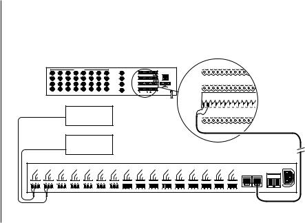
b.A star configuration (going to each receiver from a central connecting point) is sometimes more practical. Your installation will be easier to maintain and troubleshoot if you make all connections at a distribution block made of barrier terminals or at a Pelco CM9760-CDU-T distribution panel (refer to Figure 12). The total length of all control lines combined should not exceed 4,000 feet (1,219 m).
|
|
|
|
VIDEO INPUTS |
|
|
VIDEO OUTPUTS |
|
|
|
|
|
|
|
ALARMS |
|
|
|
|
|
LOCAL |
|
|
|
|
|
|
|
1 |
ALARMS |
|
|
|
|
|
LOCAL |
|
|
|
|
|
||
|
|
|
|
|
|
|
(1-9) |
|
|
|
|
KEYBOARD |
(1-9) |
|
|
|
|
|
KEYBOARD |
||
1 |
3 |
5 |
7 |
9 |
11 |
13 |
15 |
1 2 3 4 5 6 7 8 9 |
|
|
|
|
|
|
|
|
|||||
|
|
|
|
|
|
|
2 |
ALARMS |
|
|
|
|
|
|
|
|
|
|
|
|
|
|
|
|
|
|
|
|
(10-18) |
|
|
|
|
|
|
1 2 |
3 |
4 |
5 6 |
7 |
8 |
9 |
|
|
|
|
|
|
|
|
|
COM 1 (1-6) |
|
|
|
|
|
|
|||||||
|
|
|
|
|
|
|
|
10 11 1213 14 15 16 1718 |
|
REMOTE KEYBOARD(S) |
|
|
|
|
|
|
|
||||
|
|
|
|
|
|
|
3 |
COM 2 (7-12) |
|
|
|
|
|
|
ALARMS |
|
|
|
|
|
|
2 |
4 |
6 |
8 |
10 |
12 |
14 |
16 |
1 2 3 4 5 6 7 8 9 10 11 12 |
T T |
R R |
|
|
|
|
|
|
|||||
CONTROL |
|
|
|
|
+ |
+ |
|
|
|
|
|
NOTE: TO PROPERLY |
|||||||||
|
|
|
|
|
|
|
4 |
0 |
1 2 |
3 |
F F |
N N C |
|
|
(10-18) |
|
|
|
|
|
|
|
|
|
|
|
|
|
OUTPUTS |
|
|
|
|
|
|
|
|
|
|
|
|
|
|
23 O C O M
RECEIVER 2 |
|
10 11 1213 14 15 16 1718 |
|
REMOTESHIELDKEYBOARD(S)DATA CABLE |
||
NOTE: USE |
COM 1 (1-6) |
|
|
CONNECT GROUND |
||
|
COM 2 (7-12) |
|
|
ON ONE END ONLY. |
||
|
|
1 2 3 4 5 6 7 8 9 10 11 |
||||
|
CM9760-CDU-T |
12 T T |
R R |
|||
|
|
|
|
+ |
+ |
|
|
ONLY WITH |
|
|
|
||
|
CONTROL |
|
|
|
|
|
|
2-WIRE |
OUTPUTS |
|
|
|
|
RECEIVER 1 |
0 1 2 3 F |
F |
N N C |
|
||
CONTROL. |
2 |
3 |
O C O |
|
||
|
|
|
M |
|
||
|
|
|
|
TO SCU |
|
|
|
|
|
|
|
|
100-240V |
|
|
Tx+ |
|
Tx+ |
|
Tx+ |
|
Tx+ |
|
Tx+ |
|
Tx+ |
|
Tx+ |
||||||||||||||
|
|
Tx- |
|
Tx- |
|
Tx- |
|
Tx- |
|
Tx- |
|
Tx- |
|
Tx- |
||||||||||||||
1 |
|
Gnd 2 |
|
Gnd 3 |
|
Gnd 4 |
|
Gnd 5 |
|
Gnd 6 |
|
Gnd 7 |
|
Gnd 8 |
||||||||||||||
|
|
|
|
|
|
|
|
|
|
|
|
|
|
|
|
|
|
|
|
|
|
|
|
|
|
|
|
|
|
|
|
|
|
|
|
|
|
|
|
|
|
|
|
|
|
|
|
|
|
|
|
|
|
|
|
|
|
Tx+ |
Tx+ |
Tx+ |
Tx+ |
Tx+ |
Tx+ |
Tx+ |
Tx+ |
Tx+ |
OUT |
IN |
Tx- |
Tx- |
Tx- |
Tx- |
Tx- |
Tx- |
Tx- |
Tx- |
Tx- |
||
Gnd |
Gnd |
Gnd |
Gnd |
Gnd |
Gnd |
Gnd |
Gnd |
Gnd |
|
|
9 |
10 |
11 |
121 |
13 |
14 |
15 |
|
16 |
|
|
|
|
|
|
|
|
|
|
|
|
10-24 AC/DC |
Figure 12. Making Receiver Connections at a Distribution Block (CM9760-CDU-T)
12 |
Pelco Manual C523M-H (6/05) |
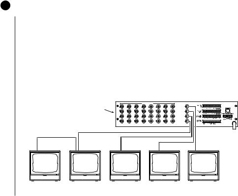
5CONNECT MONITORS
1.Your SCU will support either two or four monitors. Models CM6700-MXB4 and CM6700-MXB4-X support four monitors (Monitors 1-4). Models CM6700-MXB2 and
CM6700-MXB2-X support two monitors (Monitor 1 and 2). A CM6700-VMC2 expansion card can be added to the CM6700-MXB2 or a CM6700-VMC2-X to the CM6700-MXB2-X to increase the support to four monitors.
2.Install monitors according to the instructions provided with them.
3.Refer to Figure 13. Connect the monitor cables at the appropriate BNC receptacle on the back of the SCU.
4.Be sure to terminate cables properly at the monitors.
|
|
|
|
|
|
VIDEO INPUTS |
|
|
VIDEO OUTPUTS |
|
|
|
|
|
|
|
|
|
|
|
LOCAL |
|
CM6700 SCU |
|
|
|
|
|
|
|
1 |
KEYBOARD |
|
1 |
3 |
5 |
7 |
9 |
1 |
13 |
15 |
|
|
|
|
|
|
|
|
|
|
|
2 |
|
|
|
|
|
|
|
|
|
|
3 |
|
|
|
2 |
4 |
6 |
8 |
10 |
12 |
14 |
16 |
|
|
|
|
|
|
|
|
|
|
4 |
|
75 Ω |
LOOPING |
|
75 Ω |
|
|
|
|
75 Ω |
75 Ω |
|
MONITOR |
MONITOR |
MONITOR |
MONITOR |
MONITOR |
4b |
4a |
3 |
2 |
1 |
00049
Figure 13. Monitor Connections
Pelco Manual C523M-H (6/05) |
13 |
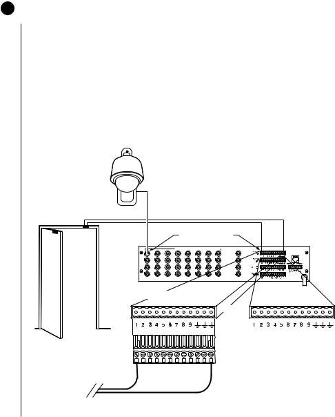
6CONNECT ALARMS
1.Refer to Figure 14. Alarm inputs 1-16 correspond to video inputs 1-16. If an open door sensor is connected to alarm input 1, when the sensor is activated the video image from camera 1 will be displayed on one of the four monitors and the camera will move to a preset (determined by programming). Alarm sensors can be either N.O. or N.C. contacts. Connect wires from the sensors to the respective alarm input points on the connectors at the back of the SCU. Each sensor requires one wire to the alarm input terminal and a return wire to one of the ground terminals on the connector.
2.Alarm inputs 17 and 18 correspond to group sequences 1 and 2. During a group sequence four video inputs are sequentially shown on a monitor. Each of the four monitors can be programmed to show the images from four different video sources. An alarm sensed at input 17 or 18 causes the respective group sequence to operate.
Connect sensors for these two alarm inputs as described in step 1 above.
CAMERA 1
VIDEO INPUT CORRESPONDS
TO ALARM INPUT
VIDEO INPUTS |
|
VIDEO OUTPUTS |
LOCAL
1 |
KEYBOARD |
1 |
3 |
5 |
7 |
9 |
1 |
13 |
15 |
|
|
|
|
|
|
|
2 |
|
|
|
|
|
|
|
3 |
2 |
4 |
6 |
8 |
10 |
12 |
14 |
16 |
|
|
|
|
|
|
|
4 |
12-PIN TERMINAL STRIP
ON REAR OF SCU
ALARMS |
ALARMS |
(1-9) |
(10-18) |
(10) |
(12) |
(14) |
(16) |
(18) |
|||
(11) |
(13) |
(15) |
(17) |
||||
12-PIN PLUG-IN CONNECTOR
TO ALARM SOURCE
00047
Figure 14. Connecting Alarms
14 |
Pelco Manual C523M-H (6/05) |
 Loading...