


 Loading...
Pelco C573M-D, C544M, C572M, C549M-A, C543M-A User Manual
...A D D E N D U M
Addendum No.: C1577M-A
Date: August 4, 2004
Manuals Affected: CM9760 Series Manuals – C538M, C539M-A, C540M-B, C541M-C, C542M-B, C543M-A,
C544M, C549M-A, C572M, C573M-D, C578M, C579M, C1501M, C1503M, C1510M-QS, C1510M-A, C1520M-B, C1528M-C, C1940M, C1941M, C1942M, and C1943M
Manual Update: The CM9760-CC1 has been replaced with the CM9700-CC1 and the CM9760-MGR management software has been replaced with the CM9700-MGR management software.
Keep the following in mind when referring to the instructions contained in these manuals:
•The CM9700-CC1 contains the latest CC1 software (version 9.01 or higher), and is programmed with the new CM9700-MGR management software.
•Despite the difference in model numbers, the CM9700-CC1 functions the same as the CM9760-CC1 and most of the information in these manuals applies to version 9.01 (or higher) CPU.
•You can add the CM9700-CC1 to an existing CM9760 system if you upgrade the existing CM9760-CC1 units with the current software (version level 9.01 or higher).
Software version 9.01 requires a minimum of 16 MB of RAM in the CPU. If required, you can upgrade the RAM in older CM9760-CC1 units using the software upgrade kit appropriate for your CPU.
•Do not use the CM9760-MGR instructions contained in these manuals. Refer to the CM9700-MGR Getting Started Software Guide, on-screen help, or Online Help for instructions.
Pelco World Headquarters • 3500 Pelco Way, Clovis, California 93612-5699 USA • www.pelco.com
USA & Canada: Tel: 800/289-9100 • Fax: 800/289-9150
 ® International: Tel: 1-559/292-1981 • Fax: 1-559/348-1120
SYSTEM |
Master |
CM9760-MDA |
|
|
Distribution |
Amplifier |
|
|
Made In USA |
CM9760-MDA
System 9760®
Master Distribution
Amplifier
Installation/
Operation Manual
C573M-D (11/03)
Pelco World Headquarters • 3500 Pelco Way, Clovis, CA 93612-5699 USA • www.pelco.com
USA & Canada: Tel: 800/289-9100 • Fax: 800/289-9150
International: Tel: 1-559/292-1981 • Fax: 1-559/348-1120

CONTENTS |
|
Section |
Page |
IMPORTANT SAFEGUARDS AND WARNINGS ................................................................ |
4 |
DESCRIPTION ................................................................................................................... |
4 |
OVERVIEW ................................................................................................................ |
4 |
MODELS .................................................................................................................... |
6 |
MOUNTING ........................................................................................................................ |
6 |
HARDWARE SETUP ......................................................................................................... |
6 |
COMMUNICATION .................................................................................................... |
6 |
COMMUNICATION PORTS SETUP .......................................................................... |
7 |
ADDRESS SETUP FOR DAISY CHAINING .............................................................. |
8 |
SETTING UP A UNIT AS THE MASTER CLOCK ...................................................... |
9 |
RESETTING TO FACTORY DEFAULTS .................................................................... |
9 |
CLEARING TITLE/TIME/DATE TEXT DISPLAY ON ALL CHANNELS ..................... |
10 |
VIDEO CONNECTIONS ........................................................................................... |
10 |
DATA CONNECTIONS .............................................................................................. |
11 |
CONNECTING THE MDA TO A SYSTEM 9740/9760 |
|
CONTROLLER ................................................................................................. |
11 |
CONNECTING THE MDA TO AN EXTERNAL PC ........................................... |
12 |
CONNECTING THE MDA TO A CM9760-KBD KEYBOARD ............................ |
13 |
CONNECTING THE MDA TO A KBD200A OR KBD300A KEYBOARD ........... |
13 |
POWER CONNECTIONS ......................................................................................... |
14 |
PROGRAMMING .............................................................................................................. |
15 |
TIME AND DATE SETUP .......................................................................................... |
15 |
PROGRAMMING METHODS ................................................................................... |
15 |
PROGRAMMING WITH A KEYBOARD .................................................................... |
15 |
KEYBOARD KEYS AND JOYSTICK ................................................................ |
15 |
ENTERING THE PROGRAMMING MODE WITH THE CM9760-KBD ............. |
16 |
ENTERING THE PROGRAMMING MODE WITH THE KBD200A OR |
|
KBD300A KEYBOARD ..................................................................................... |
16 |
MAIN MENU ..................................................................................................... |
17 |
SET CAMERA TITLE ........................................................................................ |
17 |
SET CABLE COMPENSATION ........................................................................ |
18 |
SET CAMERA DISPLAY ................................................................................... |
18 |
SET TIME AND DATE ....................................................................................... |
20 |
SET PORT ........................................................................................................ |
21 |
RESET MDA ..................................................................................................... |
22 |
PROGRAMMING WITH THE CM9760-MDA SETUP PROGRAM ............................ |
22 |
CM9760-MDA SETUP PROGRAM DESCRIPTION ......................................... |
22 |
SYSTEM REQUIREMENTS ............................................................................. |
22 |
INSTALLING THE CM9760-MDA SETUP PROGRAM ............................................. |
23 |
STARTING THE CM9760-MDA SETUP PROGRAM ................................................ |
24 |
CM9760-MDA SETUP DIALOG BOX ............................................................... |
25 |
SET PASSWORD ............................................................................................. |
25 |
SET UNIT ID ..................................................................................................... |
26 |
SET SYSTEM ................................................................................................... |
26 |
SET TIME AND DATE ....................................................................................... |
28 |
SET TITLES ...................................................................................................... |
29 |
SET CABLE COMPENSATION ........................................................................ |
31 |
SET DISPLAY ................................................................................................... |
32 |
SET MESSAGE TEXT ...................................................................................... |
34 |
SEND DATA ...................................................................................................... |
40 |
VIDEO ALPHANUMERIC OVERLAYS ..................................................................... |
40 |
TROUBLESHOOTING ...................................................................................................... |
41 |
SPECIFICATIONS ............................................................................................................. |
42 |
APPENDIX A – APPLICATIONS ....................................................................................... |
44 |
APPENDIX B – SUPPORTED TITLE AND MESSAGE TEXT CHARACTERS ................. |
56 |
APPENDIX C – MESSAGE TEXT INSERTION COMMANDS .......................................... |
57 |
WARRANTY AND RETURN INFORMATION .................................................................... |
60 |
2 |
|
Pelco Manual C573M-D (11/03) |
|

LIST OF ILLUSTRATIONS |
|
|
Figure |
|
Page |
1 |
System Configuration (Rear Panel View) ........................................................... |
5 |
2 |
Location of DIP Switches ................................................................................... |
7 |
3 |
DIP Switch .......................................................................................................... |
7 |
4 |
Connecting the MDA to a System 9760 ............................................................ |
11 |
5 |
PC Connection to CM9760-MDA ...................................................................... |
12 |
6 |
CM9760-KBD Setup for Direct Control ............................................................. |
13 |
7 |
Keyboard Rear Panel ........................................................................................ |
13 |
8 |
CM9760-MDA Keyboard Wiring ........................................................................ |
14 |
9 |
Main Menu ........................................................................................................ |
17 |
10 |
Set Camera Title Menu ..................................................................................... |
17 |
11 |
Set Cable Compensation Menu ........................................................................ |
18 |
12 |
Set Camera Display Menu ................................................................................ |
18 |
13 |
Set Time and Date Menu .................................................................................. |
20 |
14 |
Set Port Menu ................................................................................................... |
21 |
15 |
Reset CM9760-MDA Screen ............................................................................. |
22 |
16 |
Login Dialog Box ............................................................................................... |
24 |
17 |
CM9760-MDA Setup Dialog Box ....................................................................... |
24 |
18 |
Old Password Dialog Box ................................................................................. |
25 |
19 |
New Password Dialog Box ................................................................................ |
25 |
20 |
Unit ID Dialog Box ............................................................................................. |
26 |
21 |
MDA COM 1 Setup Dialog Box ......................................................................... |
26 |
22 |
System Communication Setup Dialog Box ....................................................... |
27 |
23 |
Set Time and Date Dialog Box .......................................................................... |
28 |
24 |
Setting Titles Using the CM9760-MDA SETUP Dialog Box .............................. |
29 |
25 |
Set Cable Compensation Dialog Box ................................................................ |
31 |
26 |
Display Dialog Box ............................................................................................ |
32 |
27 |
Position Text Dialog Box ................................................................................... |
33 |
28 |
Adjust Brightness Dialog Box ............................................................................ |
33 |
29 |
Output On/Off Dialog Box ................................................................................. |
33 |
30 |
Input On/Off Dialog Box .................................................................................... |
33 |
31 |
Message Text Editing Dialog Box ...................................................................... |
34 |
32 |
Command Data Window ................................................................................... |
35 |
33 |
Sample Display Screen Example ...................................................................... |
37 |
34 |
Sample Command Data Window ...................................................................... |
38 |
35 |
Typical Camera Display With Alphanumerics ................................................... |
40 |
36 |
CM9760-MDA Dimension Drawing ................................................................... |
43 |
37 |
Simple System Configuration ............................................................................ |
45 |
38 |
Master MDA Time and Date Generator for 63 MDA Slave Units |
|
|
(64 Total MDA Units) ......................................................................................... |
46 |
39 |
PC Connection to Up to 16 Daisy-Chained MDA Units ..................................... |
47 |
40 |
PC Connection to over 16 MDA Units (Maximum of 64 MDA Units) ................. |
48 |
41 |
CM9760-CC1 Connection to up to 16 Daisy-Chained MDA Units .................... |
49 |
42 |
CM9760-CC1 Connection to over 16 MDA Units |
|
|
(Maximum of 64 MDA Units) ............................................................................. |
50 |
43 |
MDA Connected to Multiplexers ........................................................................ |
51 |
44 |
Non-Coaxitron System Setup ........................................................................... |
52 |
45 |
Coaxitron with System 9760 Setup ................................................................... |
53 |
46 |
Coaxitron with System 6800 Setup ................................................................... |
54 |
47 |
CM9760-MDA Message Text Sent from Third-Party Equipment ....................... |
55 |
LIST OF TABLES |
|
|
Table |
|
Page |
A |
Port Setup Switch Settings ................................................................................ |
7 |
B |
Address Switch Settings .................................................................................... |
8 |
C |
Video Coaxial Cable Wiring Distances .............................................................. |
10 |
D |
MDA RJ-45 Connector Pin-Outs ....................................................................... |
12 |
E |
CM9760-CC1/CM9760-MDA Format Matchup ................................................. |
20 |
F |
CM9760-CC1/CM9760-MDA Compatible Date Styles and Time Formats ........ |
29 |
G |
Supported Title and Message Text Character Set ............................................. |
56 |
H |
CM9760-MDA Message Text Insertion Commands .......................................... |
57 |
Pelco Manual C573M-D (11/03) |
3 |

IMPORTANT SAFEGUARDS AND WARNINGS
Observe the following WARNINGS before installing and using this product.
1.Installation and servicing should be done by qualified service personnel only and conform to all local codes.
2.Unless the unit meets NEMA Type 3, 3R, 3S, 4, 4X, 6, or 6P standards, it is designed for indoor use only and must not be installed where exposed to rain and moisture.
3.Only use replacement parts Pelco recommends.
4.After replacing/repairing this unit’s electrical components, conduct a resistance measurement between line and exposed parts to verify the exposed parts have not been connected to line circuitry.
The product and/or manual may bear the following marks:
This symbol indicates that dangerous voltage constituting a risk of electric shock is present within this unit.
This symbol indicates that there are important operating and maintenance instructions in the literature accompanying this unit.
CAUTION:
RISK OF ELECTRIC SHOCK.
DO NOT OPEN.
Please thoroughly familiarize yourself with the information in this manual prior to installation and operation.
DESCRIPTION
OVERVIEW
The CM9760 master distribution amplifier (CM9760-MDA), version 2.05 or higher, is a 16-channel video distribution amplifier that distributes video to multiple devices without image degradation. As illustrated in Figure 1, each of the 16 channels (video inputs) has four independent video outputs. Each of the video outputs can be connected to any of the following devices:
•Monitor
•Video printer
•Video cassette recorder (VCR)
•Digital video recorder (DVR)
•Multiplexer
•Matrix switcher
4 |
|
Pelco Manual C573M-D (11/03) |
|

CAMERA
CAMERA INPUT
1 |
2 |
3 |
4 |
5 |
6 |
7 |
INPUT |
10 |
11 |
12 |
13 |
14 |
15 |
16 |
|
|
8 |
9 |
|
||||||||||||||
A |
|
|
|
|
|
|
|
|
|
|
|
|
|
|
PGM |
120VAC |
|
|
|
|
|
|
|
|
|
|
|
|
|
|
|
||
|
|
|
|
|
|
|
|
|
|
|
|
|
|
|
MON |
|
B |
|
|
|
|
|
|
|
|
|
|
|
|
|
|
|
|
C |
|
|
|
|
|
|
|
|
|
|
|
|
|
|
|
|
D |
|
|
|
|
|
|
|
|
|
|
|
|
|
|
|
COM1 COM2 |
|
|
|
|
|
|
|
|
|
|
|
|
|
|
|
UNIT ID |
|
|
|
|
|
|
|
|
|
|
|
|
|
|
|
|
|
|
|
|
|
|
|
|
|
OUTPUT |
|
|
|
|
|
|
|
|
|
PELCO CM9760-MDA
PELCO SYSTEM CM9760 OR
PC CONNECTED TO COM1 PORT
MONITOR |
VCR |
Figure 1. System Configuration (Rear Panel View)
NOTE: Up to 16 MDA units can be daisy-chained. If more than 16 MDAs are required, a CM9760-CDU-T must be used.
The MDA can be programmed using a PC or a CM9760-KBD, KBD200A, or KBD300A keyboard. Each of the 16 video inputs can be individually programmed to insert time/date and title information on each video output, and each video output is selectable to include or exclude time/date and title generation. Character positions are adjustable horizontally and vertically on-screen with digital brightness control. Programming also includes cable compensation for up to 1,500 feet (457 m) of RG59/U coaxial cable.
The MDA can act as a stand-alone time/date and title generator or can be synchronized to a System 9740™/System 9760® as a matrix time/date and title generator:
•As a stand-alone unit, an MDA can be addressed to provide the master time and date for up to 63 MDA slave units.
•When connected to a System 9740/System 9760 CC1 port, up to 64 MDAs can accept the master time and date from the 9740/9760.
In addition, note the following about the MDA:
•Using the RS-232 or RS-422 communication standard, the MDA can accept text messages from third-party equipment. A message can contain up to 24 characters. Up to five lines of messages can be displayed simultaneously. The messages can be inserted onto any video channel independently. For additional information, refer to the Set Message Text section of this manual.
•All video inputs are individually ground isolated to prevent ground loops, eliminating the need for ground loop isolation transformers.
•Battery backup protects programming information for a minimum of one year.
•The MDA does not pass Coaxitron® signals; however, the MDA can be used with
Coaxitron products such as the CM6700, CM6800, and the CM9760-CXTA.
|
|
|
|
Pelco Manual C573M-D (11/03) |
5 |
||

MODELS |
CM9760-MDA |
Master distribution amplifier with time and date and title, 120 VAC, 60 Hz (FCC)
CM9760-MDA-X Same as CM9760-MDA except 230 VAC, 50 Hz (CE)
MOUNTING
VERY IMPORTANT: If you are going to use RS-232 communication, you must open the case to set the DIP switches—do so BEFORE mounting the MDA unit in the rack. See the section on
Communication Ports Setup and the section on Connecting the MDA to an External PC for information.
Install the MDA in a standard 19-inch (48.26 cm) equipment rack using standard mounting hardware. The MDA occupies 5.25 inches (13.34 cm) of vertical space, or three RU (rack units).
HARDWARE SETUP
The following parts are supplied:
1CM9760 Master Distribution Amplifier
1Power cord
1Data cable (reversed RJ-45 to RJ-45)
1CM9760-MDA Resource CD
COMMUNICATION
Communication between MDA units, System 9760 CC1 (controller), System 9740 CC1 (controller), KBD200A or KBD300A keyboard, or a host PC is accomplished using serial RS-232, RS-422, or RS-485 transceivers that can be configured by DIP switches on the PCB (printed circuit board). The factory default for both COM 1 and COM 2 ports is RS-422.
6 |
|
|
|
|
Pelco Manual C573M-D (11/03) |
|
|
|
|
||
|
|
|
|
||
|
|
|
|
||
|
|
|
|
||
|
|
|
|
COMMUNICATION PORTS SETUP
NOTE: COM 1 is configured at the factory for RS-422 communication. To communicate via RS-232, you must open the case and change an internal DIP switch.
ON
1 2 3 4 5 6 7 8
Figure 3. DIP Switch
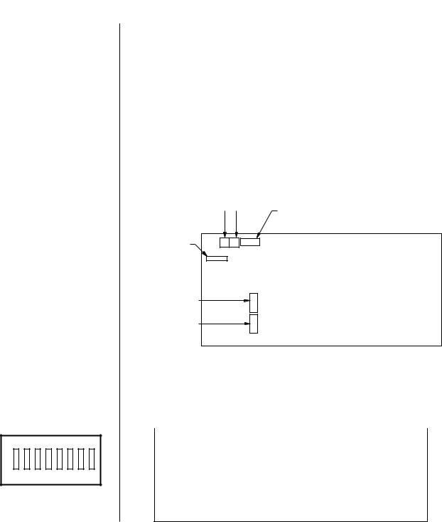
There are two sets of DIP switches inside the MDA for selecting the type of interface for the communication ports (COM 1 and COM 2).
The unit comes from the factory configured for RS-422. If your communication scheme is RS-422 and you intend to program the MDA(s) through a CM9760-KBD, KBD200A or KBD300A keyboard, leave the settings alone.
However, if the communication scheme is different than RS-422, or you are going to program the MDA through a PC (which requires RS-232), do the following to change settings. (Generally, programming through a PC is easier than programming through a System 9760 keyboard. For more information, refer to the Programming section.)
1.Remove the 10 screws on the top cover and lift it off.
2.Refer to Figure 2 for the location of the switches for COM 1 and COM 2. Refer to Table A for the switch settings.
3.Replace the cover.
COM 2 |
|
|
|
COM 1 |
|
|
FUSE |
COM 1 DIP SWITCH |
COM 2 DIP SWITCH |
UNIT ID DIP SWITCH
BACK
FRONT
Figure 2. Location of DIP Switches
Table A. Port Setup Switch Settings
|
|
SWITCH SETTINGS |
|
|
|
PORT SETUP |
|||
1 |
2 |
3 |
4 |
5 |
|
6 |
7 |
8 |
SELECTED |
|
|
|
|
|
|
|
|
|
|
OFF |
OFF |
OFF |
OFF |
ON |
|
ON |
OFF |
OFF |
RS-232 Operation |
ON |
ON |
ON |
ON |
OFF |
|
OFF |
OFF |
OFF |
RS-422 Operation* |
ON |
ON |
ON |
ON |
OFF |
|
OFF |
ON |
OFF |
RS-485 Operation |
|
|
|
|
|
|
|
|
|
|
* Factory default setting
|
|
|
|
Pelco Manual C573M-D (11/03) |
7 |
||

NOTE: When upgrading CM9760-MDA units in a daisy chain to version 2.xx, version 2.xx units must be the first units in the daisy chain. Any CM9760-MDA version 1.xx units must be connected in the chain following all version 2.xx units.
ADDRESS SETUP FOR DAISY CHAINING
CAUTION: Switch 7 clears all entered data from memory.
Table B. Address Switch Settings
|
|
|
|
SWITCH SETTINGS |
|
|
|
|
|
|
|
||
ID |
|
1 |
|
2 |
|
3 |
|
4 |
|
5 |
|
6 |
CAMERA RANGE SELECTED |
|
|
|
|
|
|
||||||||
|
|
|
|
|
|
|
|
|
|
|
|
|
|
1 |
|
OFF |
|
OFF |
|
OFF |
|
OFF |
|
OFF |
|
OFF |
Cameras 1-16 |
2 |
|
ON |
|
OFF |
|
OFF |
|
OFF |
|
OFF |
|
OFF |
Cameras 17-32 |
3 |
|
OFF |
|
ON |
|
OFF |
|
OFF |
|
OFF |
|
OFF |
Cameras 33-48 |
4 |
|
ON |
|
ON |
|
OFF |
|
OFF |
|
OFF |
|
OFF |
Cameras 49-64 |
5 |
|
OFF |
|
OFF |
|
ON |
|
OFF |
|
OFF |
|
OFF |
Cameras 65-80 |
6 |
|
ON |
|
OFF |
|
ON |
|
OFF |
|
OFF |
|
OFF |
Cameras 81-96 |
7 |
|
OFF |
|
ON |
|
ON |
|
OFF |
|
OFF |
|
OFF |
Cameras 97-112 |
8 |
|
ON |
|
ON |
|
ON |
|
OFF |
|
OFF |
|
OFF |
Cameras 113-128 |
9 |
|
OFF |
|
OFF |
|
OFF |
|
ON |
|
OFF |
|
OFF |
Cameras 129-144 |
10 |
|
ON |
|
OFF |
|
OFF |
|
ON |
|
OFF |
|
OFF |
Cameras 145-160 |
11 |
|
OFF |
|
ON |
|
OFF |
|
ON |
|
OFF |
|
OFF |
Cameras 161-176 |
12 |
|
ON |
|
ON |
|
OFF |
|
ON |
|
OFF |
|
OFF |
Cameras 177-192 |
13 |
|
OFF |
|
OFF |
|
ON |
|
ON |
|
OFF |
|
OFF |
Cameras 193-208 |
14 |
|
ON |
|
OFF |
|
ON |
|
ON |
|
OFF |
|
OFF |
Cameras 209-224 |
15 |
|
OFF |
|
ON |
|
ON |
|
ON |
|
OFF |
|
OFF |
Cameras 225-240 |
16 |
|
ON |
|
ON |
|
ON |
|
ON |
|
OFF |
|
OFF |
Cameras 241-256 |
17 |
|
OFF |
|
OFF |
|
OFF |
|
OFF |
|
ON |
|
OFF |
Cameras 257-272 |
18 |
|
ON |
|
OFF |
|
OFF |
|
OFF |
|
ON |
|
OFF |
Cameras 273-288 |
19 |
|
OFF |
|
ON |
|
OFF |
|
OFF |
|
ON |
|
OFF |
Cameras 289-304 |
20 |
|
ON |
|
ON |
|
OFF |
|
OFF |
|
ON |
|
OFF |
Cameras 305-320 |
21 |
|
OFF |
|
OFF |
|
ON |
|
OFF |
|
ON |
|
OFF |
Cameras 321-336 |
22 |
|
ON |
|
OFF |
|
ON |
|
OFF |
|
ON |
|
OFF |
Cameras 337-352 |
23 |
|
OFF |
|
ON |
|
ON |
|
OFF |
|
ON |
|
OFF |
Cameras 353-368 |
24 |
|
ON |
|
ON |
|
ON |
|
OFF |
|
ON |
|
OFF |
Cameras 369-384 |
25 |
|
OFF |
|
OFF |
|
OFF |
|
ON |
|
ON |
|
OFF |
Cameras 385-400 |
26 |
|
ON |
|
OFF |
|
OFF |
|
ON |
|
ON |
|
OFF |
Cameras 401-416 |
27 |
|
OFF |
|
ON |
|
OFF |
|
ON |
|
ON |
|
OFF |
Cameras 417-432 |
28 |
|
ON |
|
ON |
|
OFF |
|
ON |
|
ON |
|
OFF |
Cameras 433-448 |
29 |
|
OFF |
|
OFF |
|
ON |
|
ON |
|
ON |
|
OFF |
Cameras 449-464 |
30 |
|
ON |
|
OFF |
|
ON |
|
ON |
|
ON |
|
OFF |
Cameras 465-480 |
31 |
|
OFF |
|
ON |
|
ON |
|
ON |
|
ON |
|
OFF |
Cameras 481-496 |
32 |
|
ON |
|
ON |
|
ON |
|
ON |
|
ON |
|
OFF |
Cameras 497-512 |
33 |
|
OFF |
|
OFF |
|
OFF |
|
OFF |
|
OFF |
|
ON |
Cameras 513-528 |
34 |
|
ON |
|
OFF |
|
OFF |
|
OFF |
|
OFF |
|
ON |
Cameras 529-544 |
35 |
|
OFF |
|
ON |
|
OFF |
|
OFF |
|
OFF |
|
ON |
Cameras 545-560 |
36 |
|
ON |
|
ON |
|
OFF |
|
OFF |
|
OFF |
|
ON |
Cameras 561-576 |
37 |
|
OFF |
|
OFF |
|
ON |
|
OFF |
|
OFF |
|
ON |
Cameras 577-592 |
38 |
|
ON |
|
OFF |
|
ON |
|
OFF |
|
OFF |
|
ON |
Cameras 593-608 |
39 |
|
OFF |
|
ON |
|
ON |
|
OFF |
|
OFF |
|
ON |
Cameras 609-624 |
40 |
|
ON |
|
ON |
|
ON |
|
OFF |
|
OFF |
|
ON |
Cameras 625-640 |
|
|
|
|
|
|
|
|
|
|
|
|
|
|
(Continued on next page)
8 |
Pelco Manual C573M-D (11/03) |

Table B. Address Switch Settings (Continued)
|
|
|
|
SWITCH SETTINGS |
|
|
|
|
|
|
|
||
ID |
|
1 |
|
2 |
|
3 |
|
4 |
|
5 |
|
6 |
CAMERA RANGE SELECTED |
|
|
|
|
|
|
||||||||
|
|
|
|
|
|
|
|
|
|
|
|
|
|
41 |
|
OFF |
|
OFF |
|
OFF |
|
ON |
|
OFF |
|
ON |
Cameras 641-656 |
42 |
|
ON |
|
OFF |
|
OFF |
|
ON |
|
OFF |
|
ON |
Cameras 657-672 |
43 |
|
OFF |
|
ON |
|
OFF |
|
ON |
|
OFF |
|
ON |
Cameras 673-688 |
44 |
|
ON |
|
ON |
|
OFF |
|
ON |
|
OFF |
|
ON |
Cameras 689-704 |
45 |
|
OFF |
|
OFF |
|
ON |
|
ON |
|
OFF |
|
ON |
Cameras 705-720 |
46 |
|
ON |
|
OFF |
|
ON |
|
ON |
|
OFF |
|
ON |
Cameras 721-736 |
47 |
|
OFF |
|
ON |
|
ON |
|
ON |
|
OFF |
|
ON |
Cameras 737-752 |
48 |
|
ON |
|
ON |
|
ON |
|
ON |
|
OFF |
|
ON |
Cameras 753-768 |
49 |
|
OFF |
|
OFF |
|
OFF |
|
OFF |
|
ON |
|
ON |
Cameras 769-784 |
50 |
|
ON |
|
OFF |
|
OFF |
|
OFF |
|
ON |
|
ON |
Cameras 785-800 |
51 |
|
OFF |
|
ON |
|
OFF |
|
OFF |
|
ON |
|
ON |
Cameras 801-816 |
52 |
|
ON |
|
ON |
|
OFF |
|
OFF |
|
ON |
|
ON |
Cameras 817-832 |
53 |
|
OFF |
|
OFF |
|
ON |
|
OFF |
|
ON |
|
ON |
Cameras 833-848 |
54 |
|
ON |
|
OFF |
|
ON |
|
OFF |
|
ON |
|
ON |
Cameras 849-864 |
55 |
|
OFF |
|
ON |
|
ON |
|
OFF |
|
ON |
|
ON |
Cameras 865-880 |
56 |
|
ON |
|
ON |
|
ON |
|
OFF |
|
ON |
|
ON |
Cameras 881-896 |
57 |
|
OFF |
|
OFF |
|
OFF |
|
ON |
|
ON |
|
ON |
Cameras 897-912 |
58 |
|
ON |
|
OFF |
|
OFF |
|
ON |
|
ON |
|
ON |
Cameras 913-928 |
59 |
|
OFF |
|
ON |
|
OFF |
|
ON |
|
ON |
|
ON |
Cameras 929-944 |
60 |
|
ON |
|
ON |
|
OFF |
|
ON |
|
ON |
|
ON |
Cameras 945-960 |
61 |
|
OFF |
|
OFF |
|
ON |
|
ON |
|
ON |
|
ON |
Cameras 961-976 |
62 |
|
ON |
|
OFF |
|
ON |
|
ON |
|
ON |
|
ON |
Cameras 977-992 |
63 |
|
OFF |
|
ON |
|
ON |
|
ON |
|
ON |
|
ON |
Cameras 993-1008 |
64 |
|
ON |
|
ON |
|
ON |
|
ON |
|
ON |
|
ON |
Cameras 1009-1024 |
|
|
|
|
|
|
|
|
|
|
|
|
|
|
SETTING UP A UNIT AS THE MASTER CLOCK
CAUTION:
Switch 7 clears all entered data from memory.
DO NOT turn off the MDA before the reset process finishes. This can lock up the MDA and render it useless. The length of time to leave power on can vary from a few seconds to several minutes (for systems with a lot of equipment). To determine when the process finishes, look at the monitor outputs as resetting puts everything back to default status.
You can synchronize several CM9760-MDAs even when connecting them without a CM9760 switching system. The master clock can be any unit ID as long as it is the first unit of the chain. Make it the master clock by turning on switch 8 of the unit ID DIP switch on the rear panel. This unit will synchronize the time and date of all units connected to it. Only one unit can be a master clock. The remaining units are the slave units (unit ID DIP switch 8 is in the OFF position, which is the default setting). A single MDA unit can provide the master time and date for up to 63 slave units.
RESETTING TO FACTORY DEFAULTS
You can reset the CM9760-MDA to factory defaults by turning on switch 7 of the UNIT ID DIP switch located on the rear panel. Do this before powering up the unit. Now, turn on the
CM9760-MDA. This will clear all data stored in memory, such as titles and port configurations and resets them to the defaults as shipped from the factory. Then turn off the CM9760-MDA and turn switch 7 off.
|
|
|
|
Pelco Manual C573M-D (11/03) |
9 |
||
CLEARING TITLE/TIME/DATE TEXT DISPLAY ON ALL CHANNELS |
You can clear title/time/date text on all CM9760-MDA channels using a DIP switch method.
To do so, proceed as follows:
1.Turn off the MDA.
2.Set the MDA to unit ID 33:
a.Set DIP switches 1, 2, 3, 4, and 5 to the OFF position.
b.Set DIP switch 6 to the ON position.
3.Turn on the MDA.
A 30-second timer starts.
4.Before the 30 seconds elapses, change the unit ID to a setting other than unit ID 33 using the appropriate DIP switch settings.
After 30 seconds have elapsed, the MDA checks whether the unit ID is different from the initial setting of 33. If the unit ID has changed, the MDA title/time/date text display is cleared.
Note the following:
•The title/time/date text can be programmed again using the PC or a CM9760-KBD,
KBD200A, or KBD300A keyboard.
•If the MDA must be set back to unit ID 33, set the unit ID after the title/time/date text has cleared.
VIDEO CONNECTIONS |
Table C. Video Coaxial Cable Wiring Distances
Cable Type* |
Maximum Distance |
|
|
RG59/U |
750 ft (229 m) |
RG6/U |
1,000 ft (305 m) |
RG11/U |
1,500 ft (457 m) |
|
|
*Minimum cable requirements: 75 ohms impedance All-copper center conductor
All-copper braided shield with 95% braid coverage
1.Connect the remote video sources to the input BNC connectors on the rear panel of the MDA (refer to Figure 33). Refer to Table C for video coaxial wiring distances. (Note that when wiring inputs it is good installation practice to label each video input in case troubleshooting is required.)
2.Connect cables from the output BNC connectors on the MDA’s rear panel to the input connectors of monitors, VCRs, switchers, etc. (refer to Figure 33). Refer to Table C for video coaxial wiring distances.
Although the MDA does not pass Coaxitron signals, it can be used with Coaxitron products —such as the CM6700, CM6800, and CM9760-CXTA—by installing the MDA after the Coaxitron equipment (refer to Figure 45 and to Figure 46).
10 |
Pelco Manual C573M-D (11/03) |

DATA CONNECTIONS
The MDA can be connected to an external device via RS-232/422/485 standards. The distance at which it can be installed away from another device depends on the communication type and the wire size of the cable. Maximum cable distance for RS-232 serial data for
18-24 AWG is 50 feet (15.24 m) while the maximum for RS-422 and RS-485 with 24-gauge wire is 4,000 feet (1,219 m). For longer distances, junction boxes and heavier cable can be used. Pelco recommends using shielded twisted pair, such as Belden 9843 or similar cable, meeting or exceeding the basic requirements for EIA RS-422/485 applications. Decide where the MDA will be located and follow the mounting and connection instructions.
CONNECTING THE MDA TO A SYSTEM 9740/9760 CONTROLLER
The rear panel of the MDA contains two RJ-45 modular connectors for external data communication using RS-232, RS-422, or RS-485 standards. Connect the COM 1 port on the MDA’s rear panel to the next available RJ-45 output connector on the System 9740/9760 controller (refer to Figure 4 for an illustration of MDA connection to a System 9760 controller.) The System 9740/9760 controller port to which the MDA is connected must be programmed for proper communication with an MDA. Refer to the System CM9760-CC1 manual or to the System CM9740-CC1 manual for information about selecting and configuring the RJ-45 ports on the System 9740/9760 controller.
USE NEXT |
AVAILABLE |
PORT |
MDA COM 1 PORT
Figure 4. Connecting the MDA to a System 9760
Refer to Figure 37 and to Figure 38 for illustrations of connecting multiple MDA units to a System 9760 controller.
|
|
|
|
|
|
|
|
|
|
|
|
|
|
|
Pelco Manual C573M-D (11/03) |
11 |
|||
NOTE: The CM9760-MDA is configured at the factory for RS-422 communication. To communicate via RS-232, an internal DIP switch must be changed. Refer to the
Communication Ports Setup section.
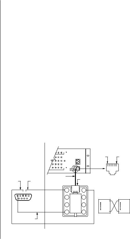
NOTE: The pin numbering of the wall block shown in Figure 5 applies to the Pelco RJ-45 wall block. A wall block purchased from a supplier other than Pelco may have a different pin numbering scheme.
CONNECTING THE MDA TO AN EXTERNAL PC
Perform this step if you are going to program your CM9760-MDA unit using a PC (personal computer).
Refer to Figure 5 and make a cable to connect the MDA to the PC. The figure shows a typical nine-pin sub “D” connector for the PC’s COM 1/COM 2 serial port. Computers may differ regarding connector types and pin-outs. Therefore, always refer to the computer’s manual to determine proper pin-outs.
If more than one MDA is to be programmed using a PC, note the following:
•A maximum of 16 MDA units can be daisy-chained. To daisy-chain up to 16 MDA units, connect the RS-422 output of the first MDA unit to the RS-422 input of the second MDA unit and continue this method until the last MDA unit is connected (refer to Table
D and to Figure 39).
•If more than 16 MDAs are to be connected to a PC, a CM9760-CDU-T must be used. Refer to Figure 40 for an example of connecting over 16 MDAs to a PC. Note that a maximum of 64 MDA units can be connected to a PC for programming.
Table D. MDA RJ-45 Connector Pin-Outs
Pin Out |
RS-232 Function |
RS-422 Function |
RS-485 Function |
|
|
|
|
1 |
Transmit |
Transmit + |
Transmit + |
2 |
No Connection |
Transmit - |
Transmit - |
3 |
No Connection |
No Connection |
No Connection |
4 |
Ground |
Ground |
Ground |
5 |
Ground |
Ground |
Ground |
6 |
No Connection |
No Connection |
No Connection |
7 |
No Connection |
Receive - |
Receive - |
8 |
Receive |
Receive + |
Receive + |
|
|
|
|
|
|
|
|
|
|
MDA SIDE |
|
|
|
|
|
|
|
|
|
|
|
CM9760-MDA |
|
|
|
|
|
|
|
14 |
15 |
16 |
|
|
PIN 8 |
PIN 1 |
|
|
|
|
|
|
PGM |
|
120V A |
||
|
|
|
|
|
|
|
|
|
||
|
|
|
|
|
|
MON |
|
|
|
|
|
|
PC SIDE |
|
|
|
|
|
|
||
|
|
|
|
|
|
|
COM1 |
COM2 |
|
COM1 RJ-45 |
|
|
|
|
|
|
|
UNI T |
|
|
CONNECTOR |
|
|
|
|
|
|
|
|
|
|
|
|
|
|
|
REVERSED CABLE |
|
RJ-45 |
|
|
||
COMPUTER |
|
|
|
COMPUTER |
|
|
|
|
|
|
|
|
|
|
|
|
CONNECTOR |
|
|
||
TRANSMIT |
|
|
|
RECEIVE |
|
|
|
|
|
|
|
|
|
|
|
|
|
REVERSED CABLE CONNECTIONS |
|||
|
|
|
|
|
|
|
|
|
||
5 |
4 |
3 |
2 |
1 |
|
8 |
|
1 |
WALL BLOCK |
CM9760-MDA |
|
|
|
|
RJ-45 |
RJ-45 |
|||||
|
|
|
|
|
|
|
|
|
||
|
|
|
|
|
|
7 |
|
2 |
CONNECTOR |
CONNECTOR |
|
|
|
|
|
|
|
|
|
||
9 |
|
8 |
7 |
6 |
|
|
|
|
PIN 1=TX |
PIN 1=TX |
|
|
|
|
|
|
|
||||
|
|
|
|
|
|
6 |
|
3 |
|
|
|
|
|
|
|
|
5 |
|
4 |
PIN 8=RX |
PIN 8=RX |
|
|
|
GROUND |
|
|
WALL BLOCK |
|
|
||
Figure 5. PC Connection to CM9760-MDA
12 |
|
Pelco Manual C573M-D (11/03) |
|

NOTE: You need two keyboard data cables for this connection. You must modify one cable as explained in Keyboard Wiring on the next page.
CONNECTING THE MDA TO A CM9760-KBD KEYBOARD
(Refer to Figure 6). Perform this step if you are going to program your CM9760-MDA unit using the CM9760-KBD keyboard. Connect the serial port of your keyboard to the COM 1 port on the MDA unit. To do more than one MDA unit, each time you will need to unhook the keyboard from the MDA unit you just programmed and hook the keyboard to the next MDA unit.
|
|
|
|
|
|
|
|
|
|
|
|
|
|
|
|
FUSE TYPE: 2AG |
|
|
|
|
|
|
|
|
|
|
|
|
|
|
|
|
|
1/4A |
SB |
|
|
|
|
|
|
|
|
|
|
|
|
|
|
|
|
|
CM9505UPS |
|
|
|
|
|
|
|
|
|
|
|
|
|
|
COAX CABLE |
|
||
|
|
|
|
|
|
|
|
|
|
|
|
|
|
|
|
CM9505UPS |
|
|
|
|
|
|
|
|
|
|
|
|
|
|
|
|
|
KEYBOARD |
CARD CAGE |
|
|
|
|
|
|
|
|
|
|
|
|
|
|
|
|
|
STRAIGHT CABLE |
1 |
2 |
|
|
|
|
|
INPUT |
|
|
12 |
|
|
|
|
|
|
|
3 |
4 |
5 |
6 |
7 |
8 |
9 |
10 |
11 |
13 |
14 |
15 |
16 |
|
|
|||
A |
|
|
|
|
|
|
|
|
|
|
|
|
|
|
PGM |
120VAC |
|
|
|
|
|
|
|
|
|
|
|
|
|
|
|
|
|
||
|
|
|
|
|
|
|
|
|
|
|
|
|
|
|
MON |
|
|
B |
|
|
|
|
|
|
|
|
|
|
|
|
|
|
|
|
|
C |
|
|
|
|
|
|
|
|
|
|
|
|
|
|
|
|
|
|
|
|
|
|
|
|
|
|
|
|
|
|
|
|
|
COM1 COM2 |
|
D |
|
|
|
|
|
|
|
|
|
|
|
|
|
|
UNIT ID |
|
|
|
|
|
|
|
|
|
OUTPUT |
|
|
|
|
|
|
|
|
|
|
CM9760-MDA |
|
|
|
|
|
|
|
|
|
|
|
COM 1 |
|
CM9760-KBD |
|||
|
|
|
|
|
|
|
|
|
|
|
|
|
|||||
= VIDEO |
REVERSED CABLE |
|
= DATA |
||
|
Figure 6. CM9760-KBD Setup for Direct Control
CONNECTING THE MDA TO A KBD200A OR KBD300A KEYBOARD
A single KBD200A or KBD300A keyboard can be used to program the CM9760-MDA
Master Distribution Amplifier. The keyboard is connected to the COM 1 port of the distribution amplifier through a KBDKIT (120 VAC) or KBDKIT-X (230 VAC) wall block and a specially modified keyboard data cable. Connect your monitor as shown in Figure 6.
Switch Settings
To set the switches in the keyboard (refer to Figure 7):
1.Remove the two screws and the DIP switch cover plate from the rear of the keyboard.
2.Place switches 5 and 8 in the ON position. This selects the CM9760-MDA mode of operation.
3.Replace the cover plate.
|
|
|
|
|
|
|
|
|
PIN 1 |
|
|
|
|
|
|
|
|
|
|
|
|
KBD200A RJ-45 |
|
||
|
|
|
|
|
|
|
|
|
JACK PINOUTS |
|
||
|
|
|
|
|
|
|
|
1 |
TX+ |
5 |
GND |
|
ON 1 |
2 |
3 |
4 |
5 |
6 |
7 |
8 |
2 |
TX– |
6 |
|
|
3 |
12 VAC/DC |
7 |
RX– |
|||||||||
|
|
|
|
|
|
|
|
|||||
|
|
|
|
|
|
|
|
4 |
}NONPOLAR |
8 |
RX+ |
|
PLACE SWITCHES 5 & 8 IN THE DOWN POSITION (MDA MODE)
Figure 7. Keyboard Rear Panel
Pelco Manual C573M-D (11/03) |
13 |

Keyboard Wiring
Refer to Figure 8.
1.Use the supplied keyboard data cable to connect the keyboard to the RJ-45 jack on the wall block.
2.Remove the RJ-45 plug from one end of a second keyboard data cable and strip the cable jacket back 2 inches (5 cm).
3.Hold up the end of the cable that has the RJ-45 plug still attached and examine the wire colors going to each pin. (Refer to the “check wire colors” detail in Figure 8.) Make note of the colors going to pins 7 and 8.
4.Connect the stripped wires to the wall block as follows:
Wire from RJ-45 pin 8 to wall block terminal 1;
Wire from RJ-45 pin 7 to wall block terminal 2;
Cut the unused wires back to the cable jacket.
5.Plug the RJ-45 end of the second (modified) keyboard data cable into the COM1 port on the master distribution amplifier.
6.Plug the KBDKIT or KBDKIT-X into a suitable outlet.
POWER CONNECTIONS
NOTE: Always replace blown fuses with fuses of the same rating. Failure to do so could result in serious damage to the unit.
The MDA’s rear panel contains a three-pronged 120 VAC receptacle. Use the supplied power cord to connect the MDA to a power source.
|
CHECK WIRE COLORS DETAIL |
|
RJ-45 PLUG |
|
PIN 7 |
COM1 |
PIN 8 |
|
|
|
HOLD WITH |
|
|
LOCKING CLIP |
|
|
ON BOTTOM |
FROM PIN 7 |
FROM PIN 8 |
TO WALL BLOCK |
|
||
|
|
TERMINALS |
4 |
5 |
PIN 1 |
KBD200A |
36
TX– 2 |
7 |
TX+ 1


 8
8
 12 VAC
KBDKIT OR |
25-FOOT KEYBOARD |
|
KBDKIT-X |
||
DATA CABLE |
||
|
Figure 8. CM9760-MDA Keyboard Wiring
14 |
Pelco Manual C573M-D (11/03) |

PROGRAMMING
TIME AND DATE SETUP
You can apply a single time and date and camera title to each input channel, which will appear on all four output channels. You can also select whether the channel will display:
•Time, date, and title
•Time and date only
•Title only
•No added text
In addition, you can select:
NOTE: The CM9760-MDA Setup program provides an interface that supports the message text feature of the MDA. (For additional information, refer to the Set Message Text section of this manual.) The CM9760-KBD, KBD200A, and KBD300A keyboards do not provide an interface that supports message text.
•Time and date format, and set the title to be displayed
•Character brightness
•On-screen location for time, date, and title
PROGRAMMING METHODS
The MDA unit is password protected and can be programmed by using a CM9760-KBD,
KBD200A, or KBD300A keyboard or by using a PC.
There are two DIP switches to select the input and output port formats, and one to identify the MDA unit. See the Communication Ports Setup and Address Setup for Daisy Chaining sections for information on the DIP switches.
You can program the unit in two ways.
•The first method uses a CM9760-KBD, KBD200A, or KBD300A keyboard and the programming monitor output. See the Programming with a Keyboard section for instructions.
•The second method requires a PC running Microsoft® Windows® and the CM9760-MDA Setup program. See the Programming with the CM9760-MDA Setup Program section for instructions.
PROGRAMMING WITH A KEYBOARD
The KBD200A uses keys for pan/tilt, while the CM9760-KBD and KBD300A use a joystick.
KEYBOARD KEYS AND JOYSTICK
Use the keyboard and the programming video output to manually program the CM9760-MDA.
Any joystick motion or pan/tilt key activates the Main Menu. Use the joystick or pan/tilt keys to navigate menus. Use the following keyboard keys to program the MDA.
|
Open |
Use this key to move down through selections in program mode. |
|
Close |
Use this key to move up through selections in program mode. |
|
Near |
Use this key to quickly exit a menu and return to the Main Menu from |
|
|
any submenu or to exit program mode without having to select EXIT on |
|
|
the Main Menu. |
|
Pan/Tilt Controls |
The pan/tilt keys or joystick controls the cursor’s position. Moving the |
|
|
joystick up and down or pressing the up/down keys maneuvers through |
|
|
the menu selection. Moving the joystick left and right or pressing the |
|
|
left/right keys positions the cursor horizontally when a menu has more |
|
|
than one item on a line. Moving the cursor to the right on RETURN on |
|
|
a menu, or on any item in the Main Menu, selects the item. |
|
Blue Buttons |
(Not applicable to the KBD200A/300A keyboards.) The line of blue |
|
|
buttons directly below the CM9760-KBD keyboard screen corresponds |
|
|
to the line of icons on the bottom of the screen. To select one of the |
|
|
icons, press the blue button directly beneath it. |
|
|
|
Pelco Manual C573M-D (11/03) |
15 |

NOTE: You need a password to enter setup mode on the CM9760-KBD keyboard. The default, as set from the factory, is 1234.
ENTERING THE PROGRAMMING MODE WITH THE CM9760-KBD
Use the CM9760-KBD keyboard to program the titles, time, date, and setup of the ports.
1.To enter programming mode from the keyboard, you must first enter the setup mode for the keyboard. Attach a straight power cable from COM 1 on the rear of keyboard to the power supply. (The LCD displays the keyboard offline message.)
2.Set DIP switch 2 (on the underside of the CM9760-KBD) to ON.
3.You are prompted to enter the setup PIN. (The factory default is 1234.) Do so, and the main setup mode menu appears.
4.Press the blue button beneath the ADV icon. The Advance Setup 1 screen appears.
5.You have to set the KBD in direct mode. To do so, cycle the host type by pressing the blue buttons below the left and right arrow icons (<= and =>) until the LCD shows “HOST DIRECT CAM CTRL.”
6.Press the blue button beneath the Step Forward icon (hand that points down) to go to the next line. Change the baud rate from 4800 to 9600 by pressing the blue button beneath the right arrow icon.
7.Press the blue button beneath the SAVE icon.
8.Press the blue button beneath the exit icon (an open door).
9.Press the blue button beneath the camera icon.
10.Press the blue button beneath the Step Forward icon (hand pointing down) four times.
11.You need to define a camera. You are currently on physical 0, logical 0. You need to change the logical to 1.
a.Press the blue button beneath the DEF NUM icon (this reverses videos).
b.Press 1.
c.Press the blue button beneath the DEF NUM icon. Physical 0 should now have a logical 1.
d.Press the blue button beneath the SAVE icon.
12.Press the blue button beneath the exit icon (an open door) twice.
13.You are prompted to turn off DIP switch 2. Do so.
14.Connect a reversed cable from the power supply to COM 1 on the rear of the MDA.
15.Access the main programming menu by moving the joystick in any direction (see Figure 9, Main Menu). You can now begin programming.
16.When you finish programming, select EXIT from the Main Menu. Then disconnect the keyboard to exit programming mode.
ENTERING THE PROGRAMMING MODE WITH THE KBD200A OR KBD300A KEYBOARD
1.Access the main programming menu by moving the joystick in any direction (KBD300A) or by pressing any pan/tilt key (KBD200A) (see Figure 9, Main Menu). You can now begin programming.
2.When you finish programming, select EXIT from the Main Menu. Then disconnect the keyboard to fully exit the programming mode.
16 |
|
Pelco Manual C573M-D (11/03) |
|
NOTE: If you are using a KBD200A keyboard, use the appropriate pan/tilt key (up, down, right, left) in place of moving the joystick.
MAIN MENU
PELCO MDA UNIT 01
SOFTWARE VERSION 2.05
MAIN MENU: |
|
1. |
CAMERA TITLE |
2. |
COMPENSATION |
3. |
CAMERA DISPLAY |
4. |
TIME/DATE |
5. |
PORTS |
6. |
RESET |
7. |
EXIT |
|
Figure 9. Main Menu |
The fields in the Main Menu (Figure 9) are defined as follows: |
|
PELCO |
The first line is the title line. It contains the Unit ID as set from the MDA |
MDA UNIT |
unit’s rear panel. |
SOFTWARE |
This field shows the version of software being used. |
VERSION |
|
MAIN MENU |
This field instructs you to pick an item to set from the six selections |
|
listed or to exit the setup program. |
A number precedes each of the seven selections. It flashes when the cursor is positioned on it. To select an item, move the keyboard’s joystick up or down to position the cursor on the item you desire, then press the joystick to the right.
Selecting items 1 through 6 will display another menu. When you finish programming, select EXIT and press the joystick right, or exit by pressing the NEAR key.
SET CAMERA TITLE
If you choose item 1 on the Main Menu, the program displays the following menu:
CAMERA 01
CAMERA TITLE:
LOADING DOCK 4
RETURN
Figure 10. Set Camera Title Menu
Use this menu to enter a camera title. When the program displays this menu, the camera number flashes on the menu’s top line.
•If you want to edit the information for the camera number displayed, press the OPEN key.
•If you want a different camera, press the joystick to the right to bring up the next camera. The title already programmed for the selected camera is displayed.
Use the joystick to access the title. Move the joystick left and right to position the cursor over a character in the title. Use the OPEN/CLOSE key to access a character. Pressing the joystick right places the cursor on the next character to program.
When you finish programming the title, press the joystick down to move the cursor to RETURN on the menu and then press the joystick to the right. This returns you to the Main Menu.
|
|
|
|
Pelco Manual C573M-D (11/03) |
17 |
||

SET CABLE COMPENSATION
If you choose item 2 on the Main Menu, the program displays the following menu:
|
CABLE COMPENSATION |
|
|||
CAM CMP CAM CMP CAM CMP |
|
||||
1 |
1 |
7 |
1 |
12 |
1 |
2 |
1 |
8 |
1 |
13 |
2 |
3 |
1 |
9 |
1 |
14 |
3 |
4 |
1 |
10 |
1 |
15 |
4 |
5 |
1 |
11 |
1 |
16 |
1 |
6 |
1 |
12 |
1 |
|
|
RETURN
Figure 11. Set Cable Compensation Menu
Transmitting video signals over long distances can adversely affect video images.
However, compensation can be used to adjust for video signal degradation.
When the system displays the menu, the cursor flashes on the compensation setting for camera 1.
To change the compensation (CMP) entry, use the joystick to move to the input (1-16) for which you want to change the compensation. For example, moving the joystick down positions the cursor at the entry for camera 2. Press the OPEN key to toggle through the settings. The settings are numbered 1-4. Setting 1 is for no compensation, setting 2 is for a video input that is 500 feet (152 m) from the CM9760-MDA, setting 3 is for 1,000 feet (304 m), and setting 4 is for 1,500 feet (457 m).
To exit the menu, position the cursor on the R in RETURN and press the joystick right.
SET CAMERA DISPLAY
If you choose item 3 on the Main Menu, the program displays the following menu:
CAMERA 01 DISPLAY |
|
||
1. POSITION DISPLAY |
|
||
BRIGHTNESS: |
|
|
8 |
ENABLE TITLES: |
|
ON |
|
ENABLE TIME DATE: |
|
ON |
|
ENABLE VIDEO DISPLAY |
|
||
OUTPUT: A |
B |
C |
D |
ON |
OFF |
ON |
OFF |
RETURN
Figure 12. Set Camera Display Menu
This menu contains setup information for how the camera display will look. You can turn the camera display for each output on or off. You can also adjust and set the characters’ brightness and position. These two settings are universal for all cameras.
When the program displays this menu, the camera number on the top line flashes. Press the joystick right to select the next camera if you do not want to program output, brightness, or text position for the current camera. Use the OPEN key to select the three items to be adjusted on this menu.
18 |
|
Pelco Manual C573M-D (11/03) |
|
Loading...