


BB4N-PG
Table of contents
 Loading...
INSTALLATION
C3461M (7/09)
Spectra IV IP Series
Dome System
In-Ceiling
Heavy-Duty In-Ceiling
Pendant (shown)
Heavy-Duty Pendant
Stainless Steel Pendant

2 C3461M (7/09)

C3461M (7/09) 3
Contents
Regulatory Notices. . . . . . . . . . . . . . . . . . . . . . . . . . . . . . . . . . . . . . . . . . . . . . . . . . . . . . . . . . . . . . . . . . . . . 6
Legal Notice . . . . . . . . . . . . . . . . . . . . . . . . . . . . . . . . . . . . . . . . . . . . . . . . . . . . . . . . . . . . . . . . . . . . . 6
Open Source Software Notice . . . . . . . . . . . . . . . . . . . . . . . . . . . . . . . . . . . . . . . . . . . . . . . . . . . . . . . 6
Description . . . . . . . . . . . . . . . . . . . . . . . . . . . . . . . . . . . . . . . . . . . . . . . . . . . . . . . . . . . . . . . . . . . . . . . . . . . 7
Models . . . . . . . . . . . . . . . . . . . . . . . . . . . . . . . . . . . . . . . . . . . . . . . . . . . . . . . . . . . . . . . . . . . . . . . . . 7
Parts List. . . . . . . . . . . . . . . . . . . . . . . . . . . . . . . . . . . . . . . . . . . . . . . . . . . . . . . . . . . . . . . . . . . . . . . . 7
Mounting . . . . . . . . . . . . . . . . . . . . . . . . . . . . . . . . . . . . . . . . . . . . . . . . . . . . . . . . . . . . . . . . . . . . . . . . . . . . 8
In-Ceiling . . . . . . . . . . . . . . . . . . . . . . . . . . . . . . . . . . . . . . . . . . . . . . . . . . . . . . . . . . . . . . . . . . . . . . . 8
Heavy-Duty In-Ceiling. . . . . . . . . . . . . . . . . . . . . . . . . . . . . . . . . . . . . . . . . . . . . . . . . . . . . . . . . . . . . . 9
Pendant, Heavy-Duty Pendant, and Stainless Steel . . . . . . . . . . . . . . . . . . . . . . . . . . . . . . . . . . . . . 11
Wiring. . . . . . . . . . . . . . . . . . . . . . . . . . . . . . . . . . . . . . . . . . . . . . . . . . . . . . . . . . . . . . . . . . . . . . . . . . . . . . 12
Installing the Dome Drive. . . . . . . . . . . . . . . . . . . . . . . . . . . . . . . . . . . . . . . . . . . . . . . . . . . . . . . . . . . . . . . 18
Installing the Lower Dome . . . . . . . . . . . . . . . . . . . . . . . . . . . . . . . . . . . . . . . . . . . . . . . . . . . . . . . . . . . . . . 19
In-Ceiling . . . . . . . . . . . . . . . . . . . . . . . . . . . . . . . . . . . . . . . . . . . . . . . . . . . . . . . . . . . . . . . . . . . . . . 19
Heavy-Duty In-Ceiling. . . . . . . . . . . . . . . . . . . . . . . . . . . . . . . . . . . . . . . . . . . . . . . . . . . . . . . . . . . . . 20
Pendant. . . . . . . . . . . . . . . . . . . . . . . . . . . . . . . . . . . . . . . . . . . . . . . . . . . . . . . . . . . . . . . . . . . . . . . . 21
Heavy-Duty Pendant. . . . . . . . . . . . . . . . . . . . . . . . . . . . . . . . . . . . . . . . . . . . . . . . . . . . . . . . . . . . . . 22
Stainless Steel . . . . . . . . . . . . . . . . . . . . . . . . . . . . . . . . . . . . . . . . . . . . . . . . . . . . . . . . . . . . . . . . . . 24
Troubleshooting . . . . . . . . . . . . . . . . . . . . . . . . . . . . . . . . . . . . . . . . . . . . . . . . . . . . . . . . . . . . . . . . . . . . . . 26
Switch Settings . . . . . . . . . . . . . . . . . . . . . . . . . . . . . . . . . . . . . . . . . . . . . . . . . . . . . . . . . . . . . . . . . . . . . . 28
Specifications. . . . . . . . . . . . . . . . . . . . . . . . . . . . . . . . . . . . . . . . . . . . . . . . . . . . . . . . . . . . . . . . . . . . . . . . 37

4 C3461M (7/09)
List of Illustrations
1 Preparing the Ceiling . . . . . . . . . . . . . . . . . . . . . . . . . . . . . . . . . . . . . . . . . . . . . . . . . . . . . . . . . . . . . . 8
2 Attaching the Conduit Fitting, Lock Nut, and Safety Chain Bracket . . . . . . . . . . . . . . . . . . . . . . . . . . 8
3 Marking the Screw Hole Pattern . . . . . . . . . . . . . . . . . . . . . . . . . . . . . . . . . . . . . . . . . . . . . . . . . . . . . 9
4 Installing the Plates . . . . . . . . . . . . . . . . . . . . . . . . . . . . . . . . . . . . . . . . . . . . . . . . . . . . . . . . . . . . . . 10
5 Installing the Heavy-Duty In-Ceiling Back Box. . . . . . . . . . . . . . . . . . . . . . . . . . . . . . . . . . . . . . . . . . 10
6 Attaching the Pendant Back Box to the Mount . . . . . . . . . . . . . . . . . . . . . . . . . . . . . . . . . . . . . . . . . 11
7 Back Box Door . . . . . . . . . . . . . . . . . . . . . . . . . . . . . . . . . . . . . . . . . . . . . . . . . . . . . . . . . . . . . . . . . . 12
8 Removing the TXB-IP . . . . . . . . . . . . . . . . . . . . . . . . . . . . . . . . . . . . . . . . . . . . . . . . . . . . . . . . . . . . . 13
9 Connect the Wiring to the Circuit Board . . . . . . . . . . . . . . . . . . . . . . . . . . . . . . . . . . . . . . . . . . . . . . 14
10 Connecting Audio to the TXB-IP. . . . . . . . . . . . . . . . . . . . . . . . . . . . . . . . . . . . . . . . . . . . . . . . . . . . . 15
11 Routing the Cables in the Back Box. . . . . . . . . . . . . . . . . . . . . . . . . . . . . . . . . . . . . . . . . . . . . . . . . . 16
12 Setting the DIP Switches . . . . . . . . . . . . . . . . . . . . . . . . . . . . . . . . . . . . . . . . . . . . . . . . . . . . . . . . . . 18
13 Installing the In-Ceiling Lower Dome. . . . . . . . . . . . . . . . . . . . . . . . . . . . . . . . . . . . . . . . . . . . . . . . . 19
14 Installing the Heavy-Duty In-Ceiling Lower Dome. . . . . . . . . . . . . . . . . . . . . . . . . . . . . . . . . . . . . . . 20
15 Attaching the Leash to the Pendant Lower Dome . . . . . . . . . . . . . . . . . . . . . . . . . . . . . . . . . . . . . . . 21
16 Installing the Pendant Lower Dome. . . . . . . . . . . . . . . . . . . . . . . . . . . . . . . . . . . . . . . . . . . . . . . . . . 21
17 Installing the O-Ring. . . . . . . . . . . . . . . . . . . . . . . . . . . . . . . . . . . . . . . . . . . . . . . . . . . . . . . . . . . . . . 22
18 Installing the Heavy-Duty Pendant Lower Dome . . . . . . . . . . . . . . . . . . . . . . . . . . . . . . . . . . . . . . . . 23
19 Attaching the Leash to the Stainless Steel Lower Dome . . . . . . . . . . . . . . . . . . . . . . . . . . . . . . . . . 24
20 Installing the Stainless Steel Lower Dome . . . . . . . . . . . . . . . . . . . . . . . . . . . . . . . . . . . . . . . . . . . . 25

C3461M (7/09) 5
List of Tables
A Video Coaxial Cable Requirements . . . . . . . . . . . . . . . . . . . . . . . . . . . . . . . . . . . . . . . . . . . . . . . . . . 17
B 24 VAC/24 VDC Wiring Distances . . . . . . . . . . . . . . . . . . . . . . . . . . . . . . . . . . . . . . . . . . . . . . . . . . . 17
C Troubleshooting the Spectra IV IP Dome System . . . . . . . . . . . . . . . . . . . . . . . . . . . . . . . . . . . . . . . 26
D Switch Settings for SW2 . . . . . . . . . . . . . . . . . . . . . . . . . . . . . . . . . . . . . . . . . . . . . . . . . . . . . . . . . . 28
E Switch Settings for SW1, Pelco P-Type Control . . . . . . . . . . . . . . . . . . . . . . . . . . . . . . . . . . . . . . . . 29
F Switch Settings for SW1, Pelco D-Type Control . . . . . . . . . . . . . . . . . . . . . . . . . . . . . . . . . . . . . . . . 30

6 C3461M (7/09)
Regulatory Notices
This device complies with Part 15 of the FCC Rules. Operation is subject to the following two conditions:
(1) this device may not cause harmful interference, and (2) this device must accept any interference
received, including interference that may cause undesired operation.
RADIO AND TELEVISION INTERFERENCE
This equipment has been tested and found to comply with the limits of a Class B digital device, pursuant to
Part 15 of the FCC Rules. These limits are designed to provide reasonable protection against harmful
interference in a residential installation. This equipment generates, uses, and can radiate radio frequency
energy and, if not installed and used in accordance with the instructions, may cause harmful interference
to radio communications. However there is no guarantee that the interference will not occur in a particular
installation. If this equipment does cause harmful interference to radio or television reception, which can
be determined by turning the equipment off and on, the user is encouraged to try to correct the
interference by one or more of the following measures:
• Reorient or relocate the receiving antenna.
• Increase the separation between the equipment and the receiver.
• Connect the equipment into an outlet on a circuit different from that to which the receiver is
connected.
• Consult the dealer or an experienced radio/TV technician for help.
You may also find helpful the following booklet, prepared by the FCC: “How to Identify and Resolve
Radio-TV Interference Problems.” This booklet is available from the U.S. Government Printing Office,
Washington D.C. 20402.
Changes and modifications not expressly approved by the manufacturer or registrant of this equipment can
void your authority to operate this equipment under Federal Communications Commission’s rules.
This Class B digital apparatus complies with Canadian ICES-003.
Cet appareil numérique de la classe B est conforme à la norme NMB-003 du Canada.
LEGAL NOTICE
SOME PELCO EQUIPMENT CONTAINS, AND THE SOFTWARE ENABLES, AUDIO/VISUAL AND RECORDING
CAPABILITIES, THE IMPROPER USE OF WHICH MAY SUBJECT YOU TO CIVIL AND CRIMINAL PENALTIES.
APPLICABLE LAWS REGARDING THE USE OF SUCH CAPABILITIES VARY BETWEEN JURISDICTIONS AND
MAY REQUIRE, AMONG OTHER THINGS, EXPRESS WRITTEN CONSENT FROM RECORDED SUBJECTS.
YOU ARE SOLELY RESPONSIBLE FOR INSURING STRICT COMPLIANCE WITH SUCH LAWS AND FOR
STRICT ADHERENCE TO ANY/ALL RIGHTS OF PRIVACY AND PERSONALTY. USE OF THIS EQUIPMENT
AND/OR SOFTWARE FOR ILLEGAL SURVEILLANCE OR MONITORING SHALL BE DEEMED UNAUTHORIZED
USE IN VIOLATION OF THE END USER SOFTWARE AGREEMENT AND RESULT IN THE IMMEDIATE
TERMINATION OF YOUR LICENSE RIGHTS THEREUNDER.
OPEN SOURCE SOFTWARE NOTICE
This product includes certain open source or other software originated from third parties that is subject to
the GNU General Public License (GPL), GNU Library/Lesser General Public License (LGPL) and different
and/or additional copyright licenses, disclaimers and notices.
The exact terms of GPL, LGPL and some other licenses are provided to you with this product. Please refer
to the exact terms of the GPL and LGPL at www.fsf.org (Free Software Foundation) and
www.opensource.org (Open Source Initiative) regarding your rights under said license. You may obtain a
complete corresponding machine-readable copy of the source code of such software under the GPL or
LGPL by sending your request to digitalsupport@pelco.com and the subject line should read Source Code
Request. You will then receive a link in the e-mail for you to download the source code.
This offer is valid for a period of three (3) years from the date of the distribution of this product by Pelco.

C3461M (7/09) 7
Description
Spectra
®
IV IP was designed with ease of installation and ease of maintenance in mind. Each dome
system consists of three components: a back box, a dome drive, and a lower dome. Spectra IV IP back box
options include the following models: environmental in-ceiling (ideal for outdoor soffits), indoor in-ceiling,
standard and environmental pendant, heavy-duty, and stainless steel. Depending on the dome drive model
with which it will be used, a back box can be ordered with or without built-in back box memory. This
memory can be used to store camera and location-specific dome settings, including labels, presets,
patterns, and zones.
MODELS
PARTS LIST
BB4N-F In-ceiling, black, with back box memory
BB4N-F-E In-ceiling, black, environmental, with back box memory
BB4N-PB Pendant mount, black, standard, with back box memory
BB4N-PG Pendant mount, gray, standard, with back box memory
BB4N-PG-E Pendant mount, gray, environmental, with back box memory
BB4NT-F In-ceiling, black
BB4NT-F-E In-ceiling, black, environmental
BB4NT-PB Pendant mount, black, standard
BB4NT-PG Pendant mount, gray, standard
BB4NT-PG-E Pendant mount, gray, environmental
BB4NHD-F Heavy-duty, in-ceiling, gray, with back box memory
BB4NHD-PG Heavy-duty, pendant, gray, with back box memory
BB4NHD-PG-E Heavy-duty, environmental pendant, gray, with back box memory
BB4N-PSG-E Stainless steel, environmental pendant, gray 316 SS, with back box memory
Qty Description
1 Back box
1 Thread compound (pendant, heavy-duty pendant, and stainless steel models only)
8 Screws, 10-32 x 3-inch, Phillips flat head (heavy-duty in-ceiling model only)
1 Important Safety Instructions manual
1 Installation manual
1 Operation/Configuration manual
1 Resource disc
8 C3461M (7/09)
Mounting
IN-CEILING
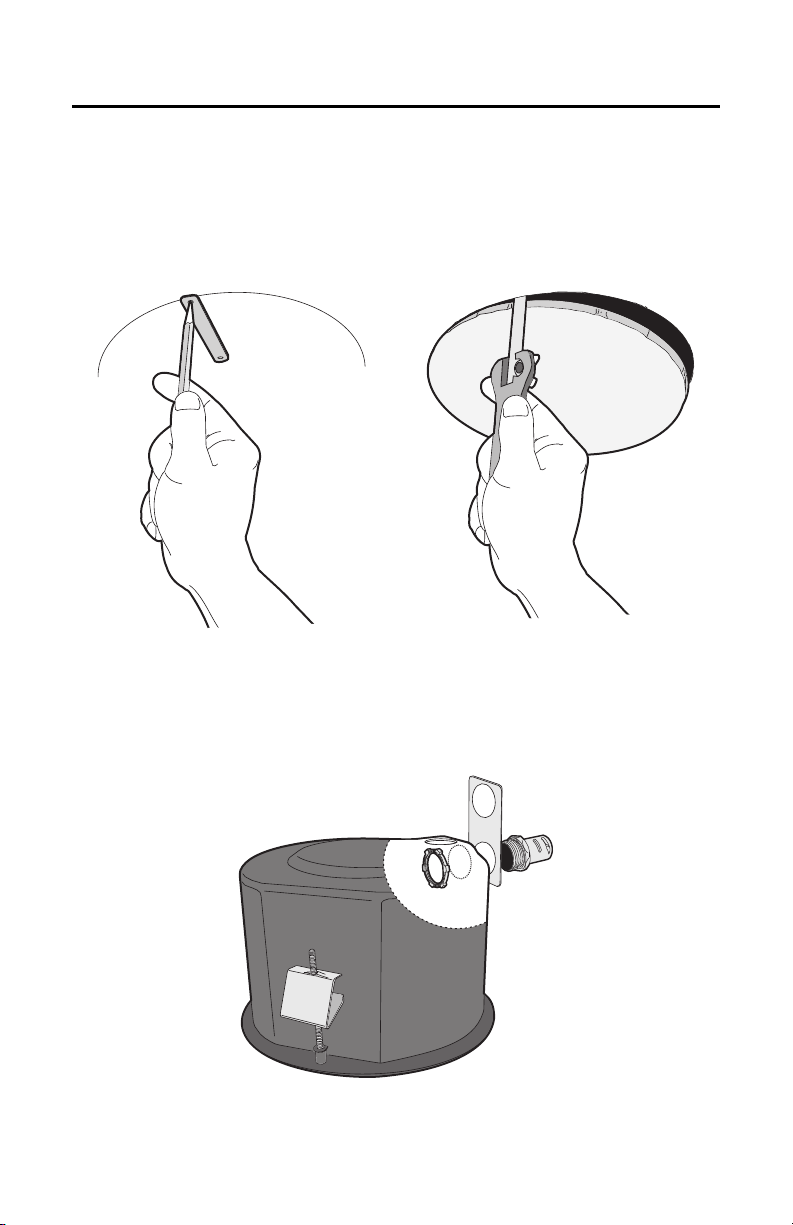
1. Prepare the ceiling (refer to Figure 1):
a. Locate the center point of the mounting location, and insert the compass tool into the ceiling.
b. Place the end of a pencil in the hole on the end of the compass tool, and draw a circle.
c. Cut out the circle.
Figure 1. Preparing the Ceiling
2. Attach a conduit fitting (not supplied), lock nut (not supplied), and safety chain bracket (refer to
Figure 2).
3. Install a safety chain/cable (not supplied), which will support up to 16 pounds (7.3 kg).
Figure 2. Attaching the Conduit Fitting, Lock Nut, and Safety Chain Bracket
C3461M (7/09) 9
4. Open the hinged door to the back box by pushing the tab lock toward the wall of the unit and lifting
the door open.
5. Pull the wiring into the back box through the conduit fitting.
6. Connect all required wiring (refer to Wiring on page 12).
7. Install the back box by compressing the spring clips and pushing the back box through the hole.
8. Tighten the screws until you hear a clicking noise.
HEAVY-DUTY IN-CEILING
1. Prepare the ceiling (refer to Figure 1 on page 8):
a. Locate the center point of the mounting location, and insert the compass tool into the ceiling.
b. Place the end of a pencil in the hole on the end of the compass tool, and draw a circle.
c. Cut out the circle.
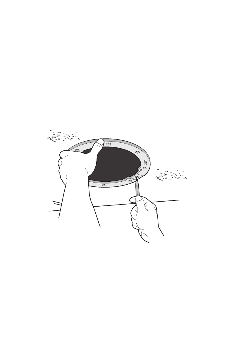
2. Use the mounting ring as a template to mark the screw hole pattern onto the mounting surface.
3. Prepare the holes.
Figure 3. Marking the Screw Hole Pattern
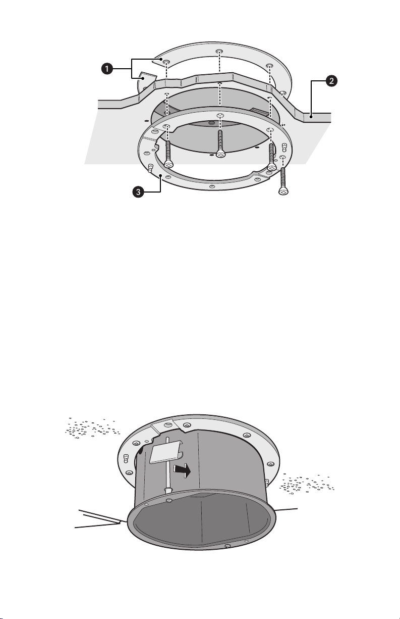
4. Install the mounting plates (refer to Figure 4 on page 10). Use the eight 10-32 x 3-inch screws
(supplied) to install the mounting ring and the two back mounting plates.
a. Line up the mounting ring with the eight fastener holes.
b. Feed one back mounting plate through the hole in the ceiling. Line up the plate with the four
fastener holes.
c. Install fasteners through the mounting ring, ceiling, and out the back mounting plate.
d. Install the second back mounting plate.
10 C3461M (7/09)
Figure 4. Installing the Plates
5. Attach a conduit fitting (not supplied), lock nut (not supplied), and safety chain bracket (refer to
Figure 2 on page 8).
6. Install a safety chain/cable (not supplied), which will support up to 16 pounds (7.3 kg).
7. Open the hinged door to the back box by pushing the tab lock toward the wall of the unit and lifting
the door open.
8. Pull the wiring into the back box through the conduit fitting.
9. Connect all required wiring (refer to Wiring on page 12).
10. Install the back box by compressing the spring clips and pushing the back box through the hole (refer
to Figure 5).
11. Tighten the screws until you hear a clicking noise.
Figure 5. Installing the Heavy-Duty In-Ceiling Back Box
ì
Back Mounting Plates
î
Ceiling
ï
Mounting Ring
C3461M (7/09) 11
PENDANT, HEAVY-DUTY PENDANT, AND STAINLESS STEEL
1. Install the mount for the pendant dome. Refer to the instructions supplied with the mount.
NOTE: If the mount is outdoors, make sure it is properly sealed to keep moisture out.
2. Open the hinged door to the back box by pushing the tab lock towards the wall of the unit and lifting
the door open.
3. Pull the wiring into the back box.
4. Connect all required wiring (refer to Wiring on page 12).
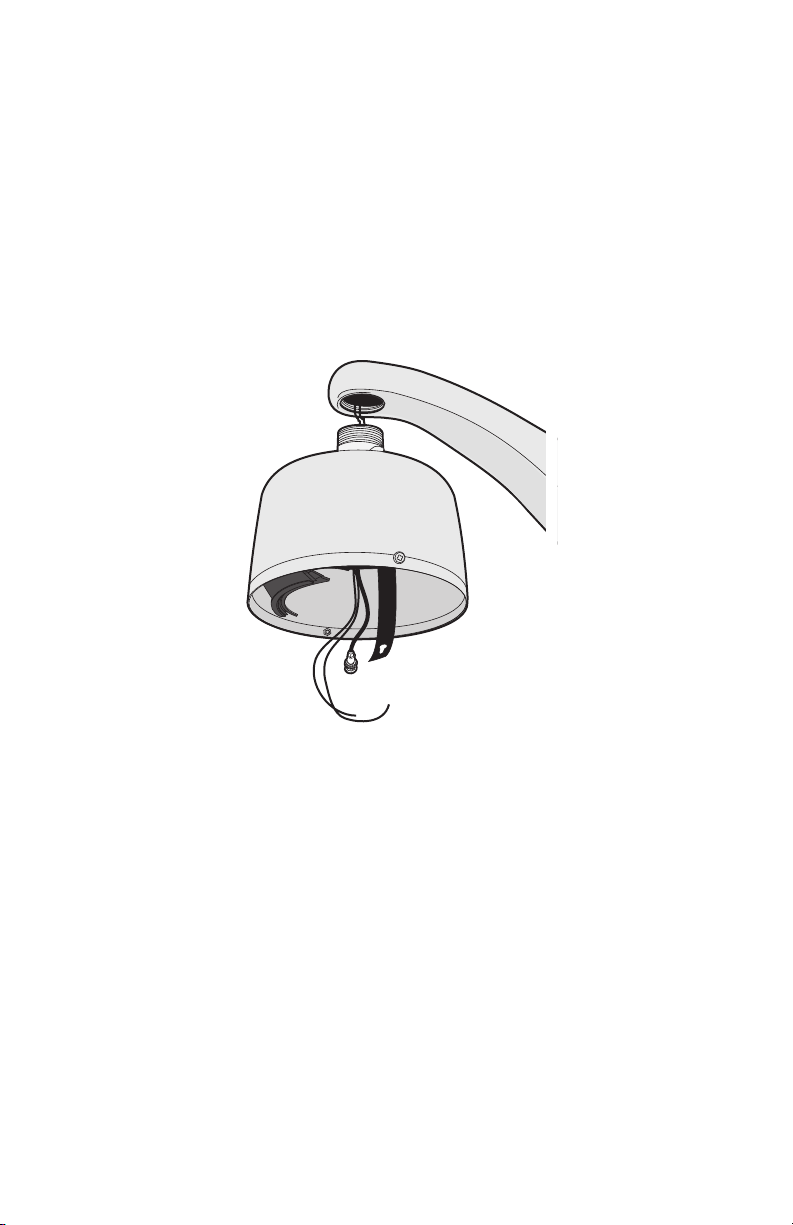
5. Screw the back box onto the mount (refer to Figure 6). If outdoors, apply thread compound (supplied)
to the threads on the back box.
NOTE: Thread compound must be applied. Not doing so may prevent the units from being separated
in the future.
Figure 6. Attaching the Pendant Back Box to the Mount
12 C3461M (7/09)
Wiring
1. Open the hinged door to the back box by pushing the tab lock toward the wall of the unit and lifting
the door open (refer to Figure 7).
Figure 7. Back Box Door
C3461M (7/09) 13
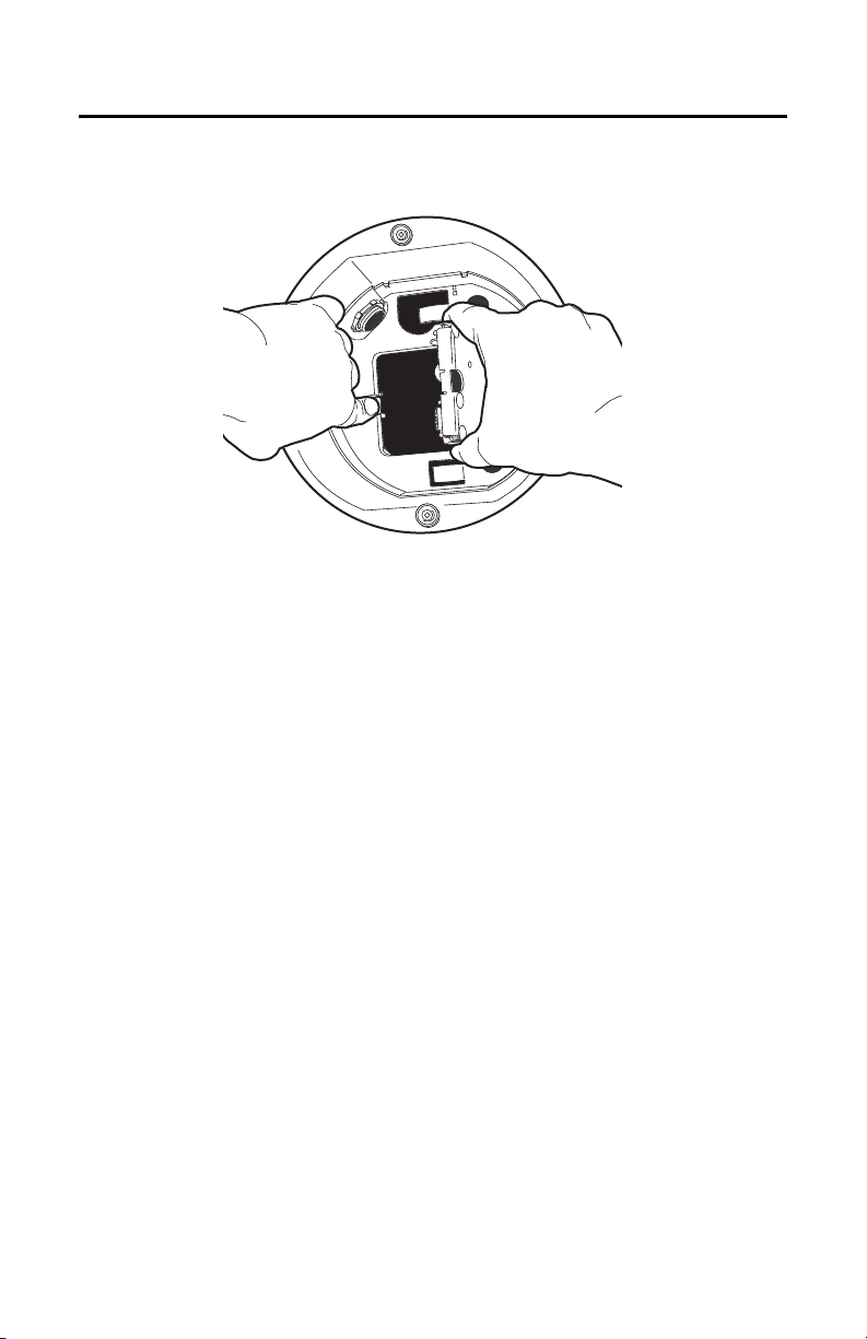
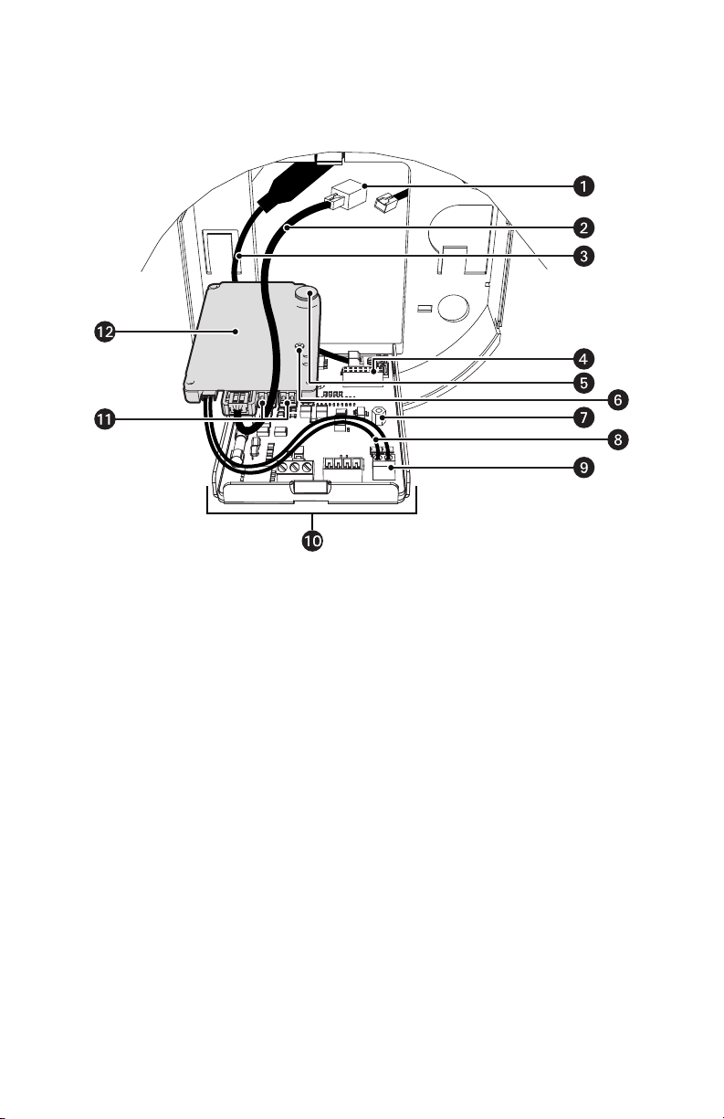
2. Remove the TXB-IP from the back box circuit board (refer to Figure 8):
a. Loosen the captive screw on the TXB-IP.
b. Carefully unplug the TXB-IP from the back box circuit board.
Figure 8. Removing the TXB-IP
ì
RJ-45 Coupler
s
Standoff
î
Ethernet Cable
t
Video UTP Cable
ï
Video Coaxial Cable
u
UTP Connector
ñ
16-Pin Connector
~í
Back Box Circuit Board
ó
Heat Sink Standoff
~â
Audio Connectors
r
Captive Screw
~ä
TXB-IP
+ -
14 C3461M (7/09)
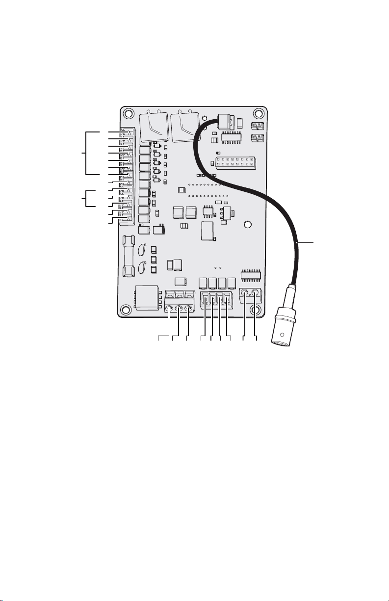
3. Connect the auxiliary, alarm, and other wiring to the back box circuit board (refer to Figure 9).
NOTES:
• Aux 1: Maximum 2 A at low voltage (<40 V)
Aux 2: Maximum 30 mA at 32 VDC
• If you are installing an environmental back box in a railway application, attach a ground wire
from the circuit board power connector to a structural ground using at least 18-gauge wire.
Figure 9. Connect the Wiring to the Circuit Board
VIDEO
UTP+ UTP-RX- RX+ TX+TX-PWR- PWR+GND
AUX2
GND
GND
NO
NC
COM
7
6
5
4
3
2
1
ALARMS
AUX1
Loading...