


Peerless D-FPF-220, SF 680, SF 680-S, SF 680P, SF 680P-S Installation Manual
...Installation and Assembly:
Universal Flat Wall Mount
Product is UL rated for screen size range and load |
|
||||
capacity |
per chart below |
|
|
||
|
|
|
|
|
|
Model # |
|
Screen Size Range |
Max UL Load Capacity |
||
D-FPF-220, D-FPF-220S, |
|
|
|||
SF 640, SF 640-S, SF 640P, |
23"-46" |
150 lb (68 kg) |
|||
SF 640P-S, RTFPF-220, |
|||||
|
|
||||
RTFPF-220S |
|
|
|
||
D-FPF-320, D-FPF-320S, |
|
|
|||
SF 660, SF 660-S, SF 660P, |
32"-60" |
200 lb (91 kg) |
|||
SF 660P-S, RTFPF-320, |
|||||
|
|
||||
RTFPF-320S |
|
|
|
||
SF 670, SF 670-S, SF 670P, |
42"-71" |
250 lb (113 kg) |
|||
SF 670P-S |
|
||||
|
|
|
|||
|
|
|
|||
SF 680, SF 680-S, SF 680P, |
61"-102" |
350 lb (159 kg) |
|||
SF 680P-S |
|
||||
|
|
|
|||
|
|
|
|
|
|
R
Features:
•For flat panel screens
•Ultra-slim design holds the screen flat against the wall
•Screen simply hooks onto the wall plate for quick and easy installation
•Includes hardware for installation to wood studs, concrete, and cinder block
3215 W. North Ave. • Melrose Park, IL 60160 • (800) 729-0307 or (708) 865-8870 • Fax: (708) 865-2941 • www.peerlessmounts.com
ISSUED: 01-06-06 SHEET #: 202-9080-2 01-26-06

Note: Read entire instruction sheet before you start installation and assembly.
 WARNING
•Do not begin to install your Peerless product until you have read and understood the instructions and warnings contained in this Installation Sheet. If you have any questions regarding any of the instructions or warnings, please call Peerless customer care at 1-800-729-0307.
•This product should only be installed by someone of good mechanical aptitude, has experience with basic building construction, and fully understands these instructions.
•Make sure that the supporting surface will safely support the combined load of the equipment and all attached hardware and components.
•Never exceed the Maximum UL Load Capacity. See page one.
•If mounting to wood wall studs, make sure that mounting screws are anchored into the center of the studs. Use of an "edge to edge" stud finder is highly recommended.
•Always use an assistant or mechanical lifting equipment to safely lift and position equipment.
•Tighten screws firmly, but do not overtighten. Overtightening can damage the items, greatly reducing their holding power.
Tools Needed for Assembly
•stud finder ("edge to edge" stud finder is recommended)
•phillips screwdriver
•drill
•1/4" bit for concrete and cinder block wall
•1/2" bit for metal stud wall
•5/32" bit for metal or wood stud wall
•level
Accessories |
|
|
• |
4 piece Metal Stud Fastener Kit (ACC 415) (Metal Stud not evaluated by UL) |
|
• |
2 piece Metal Stud Fastener Kit (ACC 215) (Metal Stud not evaluated by UL) |
|
Table of Contents |
|
|
Parts List .............................................................................................................................................................................. |
3 |
|
Installation to Double Wood Stud Wall .................................................................................................................................. |
4 |
|
Installation to Triple Wood Stud Wall .................................................................................................................................... |
5 |
|
Installation to Solid Concrete or Cinder Block ....................................................................................................................... |
6 |
|
Installing Adapter Brackets ................................................................................................................................................... |
7 |
|
Installing Flat Panel Screen to Wall Plate ............................................................................................................................. |
8 |
|
For customer care call (800) 729-0307 or (708) 865-8870.
2 of 24 |
ISSUED: 01-06-06 SHEET #: 202-9080-2 01-26-06 |
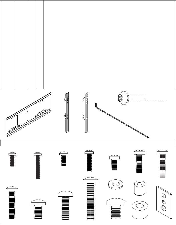
Before you begin, make sure all parts shown are included with your product.
Parts may appear slightly different than illustrated.
D-FPF220S,220,FPF- D-- SF 640,640SFS,- SF 640P,640PSFS,- RTFPFRTFPF220S220,- - |
D-FPF320S,320,FPF- D-- SF 660,660SFS,- SF 660P,660PSFS,- RTFPFRTFPF320S320,- - |
SF 670,670SFS,- SF 670P,670PSFSSF 680,680SFS,- SF 680P,680PSFS- |
Parts List |
|
Non-Security |
Security |
|
||||
|
|
Black |
Silver |
Black |
Silver |
||||||
Description |
Qty. |
Part Number |
Part Number |
Part Number |
Part Number |
||||||
! |
|
|
|
AA wall plate (double stud) |
1 |
200-1797 |
200-4797 |
200-1797 |
200-4797 |
||
|
! |
|
|
(double stud) |
|
201-1018 |
201-4018 |
201-1018 |
201-4018 |
||
|
|
! |
|
(triple stud) |
|
200-1901 |
200-4901 |
200-1901 |
200-4901 |
||
|
|
|
! |
(triple stud) |
|
200-1902 |
200-4902 |
200-1902 |
200-4902 |
||
! |
|
|
|
BB adapter bracket |
2 |
200-0758 |
200-0759 |
200-0760 |
200-0761 |
||
|
! |
|
|
|
|
200-0754 |
200-0755 |
200-0756 |
200-0757 |
||
|
|
! |
|
|
|
200-0940 |
200-0941 |
200-0942 |
200-0943 |
||
|
|
|
! |
|
|
200-0944 |
200-0945 |
200-0946 |
200-0947 |
||
|
! |
|
|
CC deep adapter bracket |
2 |
200-0750 |
200-0751 |
200-0752 |
200-0753 |
||
! |
! |
|
|
DD #14 x 2.5 wood screw |
4 |
5S1-015-C03 |
5S1-015-C03 |
5S1-015-C03 |
5S1-015-C03 |
||
|
|
! |
! |
|
6 |
5S1-015-C03 |
5S1-015-C03 |
5S1-015-C03 |
5S1-015-C03 |
||
! |
! |
|
|
EE Alligator® anchor |
4 |
590-0097 |
590-0097 |
590-0097 |
590-0097 |
||
|
|
! |
! |
|
6 |
590-0097 |
590-0097 |
590-0097 |
590-0097 |
||
! |
|
|
|
FF 4 mm allen wrench |
1 |
560-1131 |
560-1131 |
560-1131 |
560-1131 |
||
|
! |
! |
! |
|
1 |
560-1146 |
560-1146 |
560-1146 |
560-1146 |
||
|
|
|
|
|
|
|
|
|
|
|
|
DD 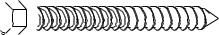

AA
EE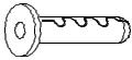
FF
BB CC
Adapter Bracket Fasteners
Note: The sorted-for-you™ fastener pack included was made specifically for your product and may not contain all components shown below.
M4 x 12 mm (6) |
M5 x 12 mm (4) |
M6 x 12 mm (4) |
|
|
M5 x 25 mm (4) |
M6 x 20 mm (4) |
|
|
|
|
|
|
M4 x 25 mm (4) |
|
M6 x 25 mm (4) |
|
|
|
|
|
|
I.D. .35" (6) |
|
|
|
|
I.D. .22" (4) |
M6 x 30 mm (4) |
M8 x 16 mm (6) M8 x 25 mm (4) M8 x 40 mm (6) |
M10 x 15 mm (4) I.D. .34" (4) multi-washer (6) |
|
|
3 of 24 |
ISSUED: 01-06-06 SHEET #: 202-9080-2 01-26-06 |
|
Installation to Double Wood Stud Wall
 WARNING
•Installer must verify that the supporting surface will safely support the combined load of the equipment and all attached hardware and components.
•Tighten wood screws so that wall plate is firmly attached, but do not overtighten. Overtightening can damage the screws, greatly reducing their holding power.
•Never tighten in excess of 80 in. • lb (9 N.M.).
•Make sure that mounting screws are anchored into the center of the stud. The use of an "edge to edge" stud finder is highly recommended.
•Hardware provided is for attachment of mount through standard thickness drywall or plaster into wood studs. Installers are responsible to provide hardware for other types of mounting situations.
|
Note: If mounting equipment weighing greater than 200 lbs, triple stud mounting is strongly recommended. |
|
Skip to page 5. |
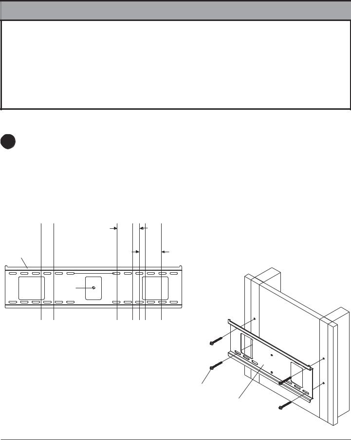
1 |
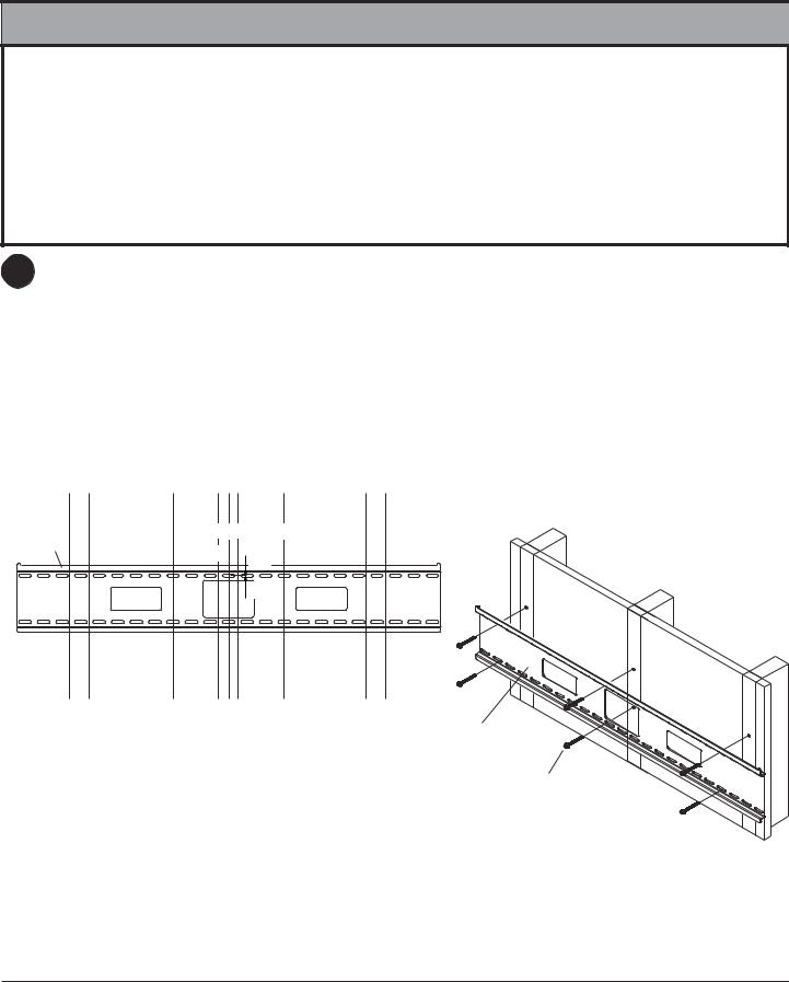
Wall plate (AA) can be mounted to two studs that are 16" apart. Use a stud finder to locate the edges of the studs. |
Use of an edge-to-edge stud finder is highly recommended. Based on their edges, draw a vertical line down each |
stud’s center. Place wall plate on wall as a template. The top mounting slots should be located above the desired screen center as indicated by dimension X in figure 1.1 and chart below. Level plate, and mark the center of the four mounting holes. Make sure that the mounting holes are on the stud centerlines. Drill four 5/32" (4 mm) dia. holes 2- 1/2" (65 mm) deep. Make sure that the wall plate is level, secure it using four #14 x 2.5" wood screws (DD) as shown in figure 1.2.
Note: Wall plate may be mounted up to 4" (102 mm) off center as shown in figure 1.1.
Skip to step 2 on page 7.
4" (102 mm)
STUD 
AA
X 
CS
CS = center of screen |
fig. 1.1 |
|
|
Model # |
X Dimension |
SF 640, SF 640-S, SF 640P, |
|
SF 640P-S, RTFPF-220, |
2.5" (64 mm) |
RTFPF-220S |
|
|
|
SF 660, SF 660-S, SF 660P, |
|
SF 660P-S, RTFPF-320, |
4-5/8" (117 mm) |
RTFPF-320S |
|
|
|
4" (102 mm)
DD
AA
fig. 1.2
4 of 24 |
ISSUED: 01-06-06 SHEET #: 202-9080-2 01-26-06 |
Installation to Triple Wood Stud Wall
 WARNING
•Installer must verify that the supporting surface will safely support the combined load of the equipment and all attached hardware and components.
•Tighten wood screws so that wall plate is firmly attached, but do not overtighten. Overtightening can damage the screws, greatly reducing their holding power.
•Never tighten in excess of 80 in. • lb (9 N.M.).
•Make sure that mounting screws are anchored into the center of the stud. The use of an "edge to edge" stud finder is highly recommended.
•Hardware provided is for attachment of mount through standard thickness drywall or plaster into wood studs. Installers are responsible to provide hardware for other types of mounting situations.
1 |
Wall plate (AA) can be mounted to three studs that are 16" apart. Use a stud finder to locate the edges of the |
studs. Use of an edge-to-edge stud finder is highly recommended. Based on their edges, draw a vertical line down |
each stud’s center. Place wall plate on wall as a template. The top mounting slots should be located above the desired screen center as indicated by dimension X in figure 1.3 and chart below. Level plate, and mark the center of the six mounting holes. Make sure that the mounting holes are on the stud centerlines. Drill six 5/32" (4 mm) dia. holes 2-1/2" (65 mm) deep. Make sure that the wall plate is level, secure it using six #14 x 2.5" wood screws (DD) as shown in figure 1.4.
Note: When mounting equipment weighing greater than 200 lbs, triple stud mounting is strongly recommended. If mounting to two studs on 16" centers, leave an open stud in center. Wall plate may be mounted up to 6" (152 mm) off-center as shown in figure 1.3.
Skip to step 2 on page 7.
STUD 
 6"
6" 
 6"
6" 
AA
(152 mm) (152 mm)
CS

 X2
X2

CS
 X
X

CS = center of screen
fig. 1.3
AA
Model # |
X Dimension |
X2 Dimension |
|
SF 670, SF 670-S, SF 670P, |
n/a |
3/4" (19 mm) |
|
SF 670P-S |
|||
|
|
||
|
|
|
|
SF 680, SF 680-S, SF 680P, |
3-3/4" (95 mm) |
n/a |
|
SF 680P-S |
|||
|
|
||
|
|
|
DD
fig. 1.4
5 of 24 |
ISSUED: 01-06-06 SHEET #: 202-9080-2 01-26-06 |

Installation to Solid Concrete or Cinder Block
 WARNING
•When installing Peerless wall mounts on cinder block, verify that you have a minimum of 1-3/8" of actual concrete thickness in the hole to be used for the concrete anchors. Do not drill into mortar joints! Be sure to mount in a solid part of the block, generally 1" minimum from the side of the block. Cinder block must meet ASTM C-90 specifications. It is suggested that a standard electric drill on slow setting is used to drill the hole instead of a hammer drill to avoid breaking out the back of the hole when entering a void or cavity.
•Concrete must be 2000 psi density minimum. Lighter density concrete may not hold concrete anchor.
•Installer must verify that the supporting surface will safely support the combined load of the equipment and all attached hardware and components.
1 |
Make sure that wall plate (AA) is level, use it as a |
template to mark four mounting holes. The top |
mounting slots should be located above the desired screen center as indicated by dimension X in figure 1.1 and charts on pages 4 and 5. Drill four 1/4" (6 mm) dia. holes to a minimum depth of 2.5" (64 mm). Insert anchors (EE) in holes flush with wall as shown (right). Place wall plate over anchors and secure with #14 x 2.5" screws (DD). Level, then tighten all fasteners. Note: Six holes and six sets of fasteners are required when mounting the wall plate for equipment weighing greater than 200 lbs.
 WARNING
•Tighten screws so that wall plate is firmly attached, but do not overtighten. Overtightening can damage screws, greatly reducing their holding power.
•Never tighten in excess of 80 in. • lb (9 N.M.).
 WARNING
1 |
concrete |
|
|
|
surface |
|
|
EE
Drill holes and insert anchors (EE).
2 |
AA |
|
DD EE
Place plate (AA) over anchors (EE) and secure with screws (DD).
3
•Always attach concrete anchors directly to loadbearing concrete.
Tighten all fasteners.
• Never attach concrete anchors to concrete covered |
|
with plaster, drywall, or other finishing material. If |
|
mounting to concrete surfaces covered with a finishing |
|
surface is unavoidable, the finishing surface must be |
|
counterbored as shown below. Be sure concrete |
AA |
anchors do not pull away from concrete when tighten- |
|
ing screws. If plaster/drywall is thicker than 5/8", |
|
custom fasteners must be supplied by installer. |
DD |
|
|
INCORRECT |
|
|
CORRECT |
VIEW |
wall |
concrete |
wall plate |
concrete |
plate |
|
|
|
|
|
|
|
|
|
CUTAWAY |
plaster/ |
|
|
plaster/ |
dry wall |
|
|
drywall |
|
|
|
|
|
|
|
|
|
|
6 of 24 |
solid |
concrete |
|
|
|
|
|
|
|
EE |
cinder |
block |
|
|
ISSUED: 01-06-06 SHEET #: 202-9080-2 01-26-06
Installing Adapter Brackets
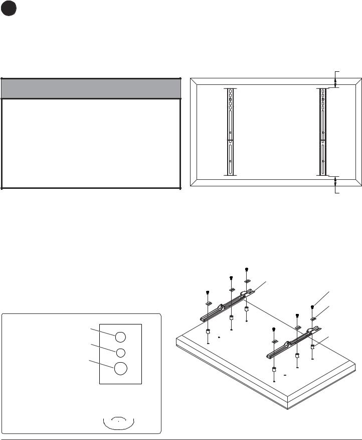
Refer to Screen Compatibility Chart to determine the proper fasteners to use.
2 To prevent scratching the screen, set a cloth on a flat, level surface that will support the weight of the screen. Place screen face side down. If screen has knobs on the back, remove them to allow the adapter brackets to be attached. Place adapter brackets (BB or CC) on back of screen, align to holes, and center on back of screen as shown in figure 2.1. Attach the adapter brackets to the back of the screen using the appropriate combination of screws, multi-wash- ers, and spacers as shown in figure 2.3.
Note: Top and bottom holes must always be used.
Verify that all holes are properly aligned, and then tighten screws using a phillips screwdriver.
 WARNING
•Tighten screws so adapter brackets are firmly attached. Do not tighten with excessive force. Overtightening can cause stress damage to screws, greatly reducing their holding power and possibly causing screw heads to become detached. Tighten to 40 in. • lb (4.5 N.M.) maximum torque.
•If screws don't get three complete turns in the screen inserts or if screws bottom out and bracket is still not tightly secured, damage may occur to screen or product may fail.
Notes:
•The number of fasteners used will vary, depending upon the type of screen.
•Multi-washers and spacers may not be used, depending upon the type of screen.
•Use the corresponding hole in the multiwasher that matches your screw size as shown in figure 2.2.
MULTI-WASHER
MEDIUMHOLEFORM5SCREWS
SMALL HOLE FOR M4 SCREWS
X
CENTERBRACKETS
VERTICALLY ON BACK OF
SCREEN
BB or CC
fig 2.1 |
X |
Note: "X" dimensions should be equal. |
BB or CC
SCREWS
MULTI-
WASHER
SPACERS
LARGE HOLE FOR M6 SCREWS
Note: Slots in SF 680, SF 680P, SF 680-S, and SF 680P-S are wider and require the use of the M8 washer I.D. .35". 
fig 2.3
fig. 2.2
7 of 24 |
ISSUED: 01-06-06 SHEET #: 202-9080-2 01-26-06 |
Mounting and Removing Flat Panel Screen
3 |
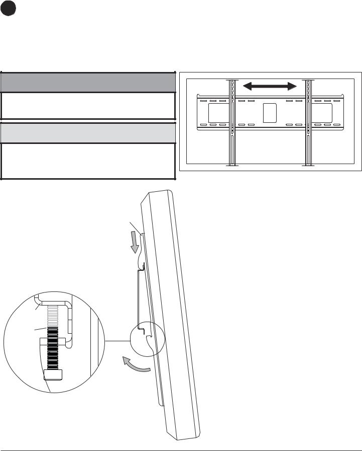
Hook adapter brackets (BB or CC) onto wall plate (AA). Then slowly swing screen in as shown. Turn safety/security |
screws, using security allen wrench (FF), clockwise at least six times to prevent screen from being removed as shown in |
detail 1 of figure 3.1.
Screen can be adjusted horizontally if desired as shown in figure 3.2.
Note: To lock the screen down, tighten safety/security screws to wall plate as shown in detail 1.
To remove screen from mount, loosen safety/security screws, swing screen away from mount, and lift screen off of mount.
 WARNING
•Always use an assistant or mechanical lifting equipment to safely lift and position the plasma television.
CAUTION
•Do not tighten screws with excessive force. Overtightening can cause damage to mount. Tighten screws to 40 in. • lb (4.5 N.M.) maximum torque.
fig 3.2
BB or CC
AA
AA
SAFETY/ SECURITY
SCREWS
BB or CC
DETAIL 1
fig 3.1
8 of 24 |
ISSUED: 01-06-06 SHEET #: 202-9080-2 01-26-06 |
© 2006 Peerless Industries, Inc. All rights reserved. Peerless is a registered trademark of Peerless Industries, Inc.
All other brand and product names are trademarks or registered trademarks of their respective owners.
 Loading...