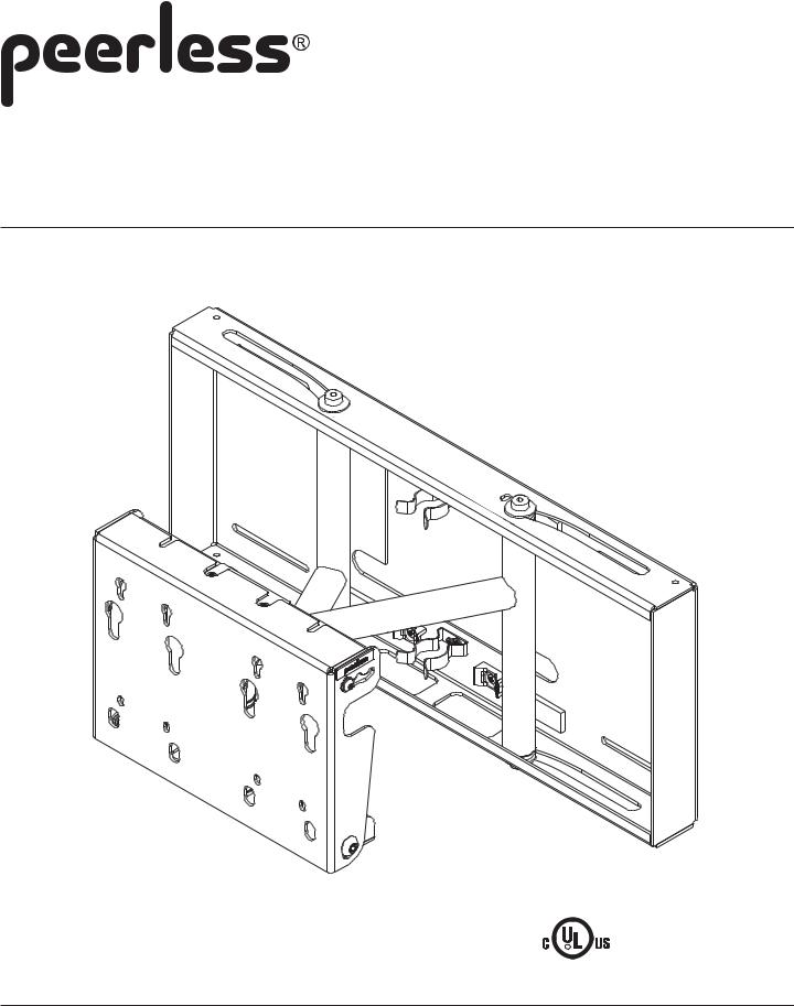
Peerless Industries SP 850P, SP 850, SP 850-S, SP 850P-S User Manual

Installation and Assembly:
Flat Panel Pull-out Swivel Wall Mount for 26" - 58" Screens
Models: SP 850, SP 850P, SP 850-S, SP 850P-S
R
This product is intended for use with UL Listed products and must be installed by a qualified professional installer.
Max Load Capacity: 150 lb (68 kg)
3215 W. North Ave. • Melrose Park, IL 60160 • (800) 729-0307 or (708) 865-8870 • Fax: (708) 865-2941 • www.peerlessmounts.com
ISSUED: 10-12-05 SHEET #: 202-9038-6 05-19-07

Note: Read entire instruction sheet before you start installation and assembly.
 WARNING
•Do not begin to install your Peerless product until you have read and understood the instructions and warnings contained in this Installation Sheet. If you have any questions regarding any of the instructions or warnings, please call Peerless customer care at 1-800-729-0307.
•This product should only be installed by a qualified professional.
•Make sure that the supporting surface will safely support the combined load of the equipment and all attached hardware and components.
•Never exceed the Maximum UL Load Capacity of 150 lb (68 kg).
•If mounting to wood wall studs, make sure that mounting screws are anchored into the center of the studs. Use of an "edge to edge" stud finder is highly recommended.
•Do not lift more weight than you can handle. Use additional man power or mechanical lifting equipment to safely handle placement of the screen.
•Tighten screws firmly, but do not overtighten. Overtightening can damage the items, greatly reducing their holding power.
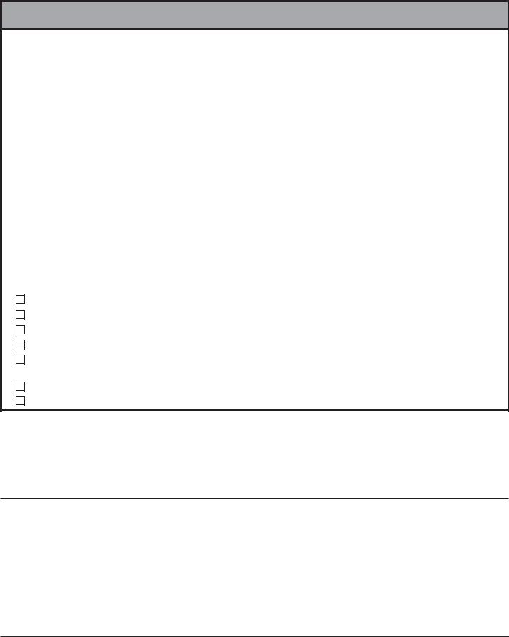
•This product was designed and intended to be mounted to the following supporting surfaces checked below with the hardware included in this product as specified in the installation sheet. To mount this product to an alternative supporting surface, contact Peerless customer care at 1 800 865-2112.
•This product was designed to be installed on the following wall construction only;
|
WALL CONSTRUCTION |
ADDITIONAL HARDWARE REQUIRED |
|
|
|
|
x |
Wood Stud |
None |
|
|
|
x |
Wood Beam |
None |
|
|
|
x |
Solid Concrete |
None |
|
|
|
x |
Cinder Block |
None |
|
|
|
|
Metal Stud |
Do not attach except with Peerless accessory kit for metal studs; |
|
|
|
|
|
Contact Customer Service for Peerless accessory kit for metal studs. |
|
|
|
|
Brick |
Contact Customer Service |
|
|
|
|
Other or unsure? |
Contact Customer Service |
|
|
Tools Needed for Assembly |
|
|
|||
• |
stud finder ("edge to edge" stud finder is recommended) • 3/8" socket wrench (3/8" extended driver is recommended) |
||||
• |
phillips screwdriver • drill |
• 1/4" bit for concrete and cinder block wall • |
5/32" bit for wood stud wall |
|
|
• |
level |
• 6 mm allen wrench (if attaching to PLP models) |
|
|
|
Table of Contents |
|
|
|
||
Parts List .............................................................................................................................................................................. |
|
|
3 |
||
Installation to Wood Stud Wall ............................................................................................................................................. |
|
|
4 |
||
Installation to Solid Concrete and Cinder Block .................................................................................................................... |
|
5 |
|||
Mounting Flat Panel Screen with VESA hole pattern ......................................................................................................... |
|
6,7 |
|||
Mounting Flat Panel Screen with Peerless PLP model adapter plate (PLP adapter plates are not UL listed) ....................... |
7 |
||||
Screen Compatibility Chart ................................................................................................................................................. |
|
|
10 |
||
For customer care call (800) 729-0307 or (708) 865-8870. |
|
|
|||
|
|
|
2 of 10 |
ISSUED: 10-12-05 SHEET #: 202-9038-6 05-19-07 |
|

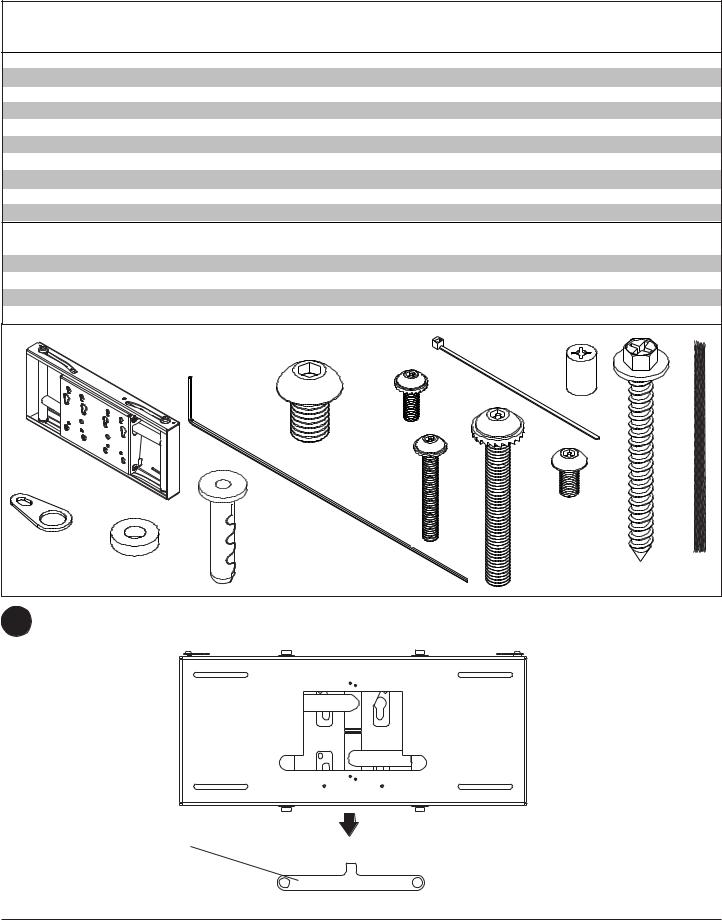
Parts List |
|
|
SP850 |
SP850P |
|
SP850-S |
SP850P-S |
||
|
Description |
|
Qty. Part # |
Part # |
|
Part # |
Part # |
|
|
A |
wall mount assembly |
|
1 |
201-0385 |
201-0386 |
|
201-0383 |
201-0384 |
|
B |
locking tab |
|
1 |
200-1871 |
200-1871 |
|
200-4871 |
200-4871 |
|
C |
.219 ID x .5 OD x .125H spacer |
|
1 |
540-1032 |
540-1032 |
|
540-1032 |
540-1032 |
|
D |
#14 x 2.5" hex head wood screw |
|
4 |
5S1-015-C03 |
5S1-015-C03 |
5S1-015-C03 |
5S1-015-C03 |
||
E |
Alligator® anchor |
|
4 |
590-0097 |
590-0097 |
|
590-0097 |
590-0097 |
|
F |
18" polyester mesh sleeve |
|
2 |
600-1014 |
600-1014 |
|
600-1014 |
600-1014 |
|
G |
cable tie |
|
4 |
560-9711 |
560-9711 |
|
560-9711 |
560-9711 |
|
K |
M10 x 15 mm socket head screw |
|
4 |
520-9262 |
520-9262 |
|
520-9262 |
520-9262 |
|
L |
.198 x .313 x .437H retaining spacer |
|
4 |
590-5005 |
590-5005 |
|
590-5005 |
590-5005 |
|
M |
4 mm security allen wrench |
|
1 |
560-1146 |
n/a |
|
560-1146 |
n/a |
|
|
|
|
|
Security |
Phillips |
|
Security |
Phillips |
|
|
|
|
|
|
(not shown) |
|
(not shown) |
||
AA |
M5 x 10 mm screw |
|
5 |
520-1063 |
520-1233 |
|
520-1063 |
520-1233 |
|
BB |
M4 x 12 mm screw |
|
4 |
510-1079 |
504-9013 |
|
510-1079 |
504-9013 |
|
CC |
M4 x 20 mm screw |
|
4 |
510-1061 |
504-9020 |
|
510-1061 |
504-9020 |
|
DD |
M5 x 40 mm screw |
|
1 |
510-1001 |
520-1199 |
|
510-1001 |
520-1199 |
|
Some parts may appear slightly different than illustrated. |
|
|
G |
L |
|
|
|||
|
A |
K |
BB |
|
|
|
|||
|
|
|
|
|
|
|
|||
|
M |
|
|
|
|
|
|
|
|
|
|
|
CC |
|
|
|
|
|
|
B |
|
|
|
|
|
|
AA |
|
|
|
E |
|
|
|
|
|
|
|
|
|
C |
|
|
|
DD |
D |
F |
||
1 |
Snap installation tab off of wall mount assembly (A). |
|
|
|
|
|
|
|
|
A
INSTALLATION TAB
3 of 10 |
ISSUED: 10-12-05 SHEET #: 202-9038-6 05-19-07 |
 Loading...