


Peerless Industries EXB-S, EXB, EXA-S, EXA-W, EXA User Manual
...
Installation and Assembly:
Projector Ceiling/Wall Mount
Model# |
Max UL Load Capacity |
|
EXA, EXA-S, EXA-W, EXB, EXB-S, |
used with PRS projector mount |
25 lb (11.3 kg) |
EXB-W, EXC, EXC-S, EXC-W |
used with PRG projector mount |
50 lb (22.7 kg) |
|
|
|
R
This product is intended for use with UL Listed products and must be installed by a qualified professional installer.
Installed to
Ceiling
Installed to Wall
(EXC models are not wall mountable due to its extensive reach)
Shown with PRG projector mount and
projector (not included)
Features:
•For use with PRG-UNV and PRS-UNV Projector Mounts
•EXA and EXB series for ceiling or wall mounting
•EXC models for ceiling mounting
•Integrated cable management
•Various height adjustments for ideal viewing positions
Shown with PRS projector mount and projector (not included)
1 of 11 |
ISSUED: 1-11-08 SHEET #: 055-9495-2 10-16-08 |
Visit the Peerless Web Site at www.peerlessmounts.com |
For customer care call 1-800-865-2112 or 708-865-8870. |
3215 W. North Ave. • Melrose Park, IL 60160 • (800) 865-2112 or (708) 865-8870 |
• Fax: (708) 865-2941 • www.peerlessmounts.com |
Note: Read entire instruction sheet before you start installation and assembly.
 WARNING
•Do not begin to install your Peerless product until you have read and understood the instructions and warnings contained in this Installation Sheet. If you have any questions regarding any of the instructions or warnings, please call Peerless customer care at 1-800-865-2112.
•This product should only be installed by someone of good mechanical aptitude, has experience with basic building construction, and fully understands these instructions.
•Make sure that the supporting surface will safely support the combined load of the equipment and all attached hardware and components.
•Never exceed the Maximum UL Load Capacity. See page 1.
•If mounting to wood ceiling/wall studs, make sure that mounting screws are anchored into the center of the studs. Use of an "edge to edge" stud finder is highly recommended.
•Always use an assistant or mechanical lifting equipment to safely lift and position equipment.
•Tighten screws firmly, but do not overtighten. Overtightening can damage the items, greatly reducing their holding power.
•This product is intended for indoor use only. Use of this product outdoors could lead to product failure and personal injury.
•This product was designed and intended to be mounted to the following supporting surfaces checked below with the hardware included in this product as specified in the installation sheet. To mount this product to an alternative supporting surface, contact Peerless customer care at 1 800 865-2112.
•This product was designed to be installed on the following ceiling/wall construction only;
CEILING/WALL CONSTRUCTION ADDITIONAL HARDWARE REQUIRED
x |
Wood Stud |
None |
|
|
|
|
x |
Wood Joist |
None |
|
|
|
|
x |
Solid Concrete |
None |
|
|
|
|
x |
Cinder Block |
None |
|
|
|
|
|
Metal Stud |
Do not attach except with Peerless accessory kit for metal studs; |
|
|||
|
|
Contact Customer Service for Peerless accessory kit for metal studs. |
|
|||
|
Brick |
Contact Customer Service |
|
|
||
|
Other or unsure? |
Contact Customer Service |
|
|
||
Tools Needed for Assembly |
|
|
|
|
||
• stud finder ("edge to edge" stud finder is recommended) |
• |
5/32" bit for wood stud or joist |
|
|||
• drill |
|
|
• |
level |
|
|
• 1/4" bit for concrete and cinder block wall |
• |
8 mm open end wrench |
|
|||
Table of Contents |
|
|
|
|
|
|
Parts List .......................................................................................................................................................................... |
|
|
|
|
3, 4 |
|
Install Outer Channel to Ceiling Plate.................................................................................................................................... |
|
|
|
|
4 |
|
Installation to Wood Joist Ceiling or Wood Stud Wall ........................................................................................................... |
|
|
|
5 |
||
Installation to Solid Concrete Ceiling or Concrete/Cinder Block Walls .................................................................................. |
|
6 |
||||
Installing Inner Channel and Routing Cables ......................................................................................................................... |
|
|
|
7 |
||
Installing Projector Mount .................................................................................................................................................. |
|
|
|
|
8-9 |
|
Installing Projector ................................................................................................................................................................ |
|
|
|
|
9 |
|
Adjusting Mount Extension ................................................................................................................................................. |
|
|
|
|
10 |
|
Install Cable Covers ............................................................................................................................................................ |
|
|
|
|
10 |
|
Projector Alignment ............................................................................................................................................................ |
|
|
|
|
11 |
|
|
|
|
2 of 11 |
ISSUED: 1-11-08 SHEET #: 055-9495-2 |
10-16-08 |
|
Visit the Peerless Web Site at www.peerlessmounts.com |
For customer care call 1-800-865-2112 or 708-865-8870. |

Before you begin, make sure all parts shown are included with your product.
Parts List |
|
EXA, |
EXA-S, |
EXA-W, |
|
|
|
|
|
EXB |
EXB-S |
EXB-W |
EXC |
EXC-S |
EXC-W |
||
|
Description |
Qty. Part # |
Part # |
Part # |
Part # |
Part # |
Part # |
|
A |
ceiling plate |
1 |
055-1773 |
055-4773 |
055-2773 |
055-1773 |
055-4773 |
055-2773 |
|
|
|
|
|
|
|
|
|
B |
outer channel |
1 |
SEE CHART |
SEE CHART |
SEE CHART |
SEE CHART |
SEE CHART |
SEE CHART |
C |
inner channel |
1 |
SEE CHART |
SEE CHART |
SEE CHART |
SEE CHART |
SEE CHART |
SEE CHART |
|
|
|
|
|
|
|
|
|
D |
clamp plate |
1 |
055-1771 |
055-4771 |
055-2771 |
055-1771 |
055-4771 |
055-2771 |
E |
vertical mounting plate |
1 |
055-1876 |
055-4876 |
055-2876 |
055-1876 |
055-4876 |
055-2876 |
|
|
|
|
|
|
|
|
|
F |
horizontal mounting plate |
1 |
055-1787 |
055-4787 |
055-2787 |
N/A |
N/A |
N/A |
G |
M5 x 16 mm socket pin screw |
2 |
520-1161 |
520-2161 |
520-2161 |
520-1161 |
520-2161 |
520-2161 |
|
|
|
|
|
|
|
|
|
H |
#14 x 2.5 wood screw |
2 |
5S1-015-C03 |
5S1-015-C04 |
5S1-015-C04 |
5S1-015-C03 |
5S1-015-C04 |
5S1-015-C04 |
J |
Alligator® concrete anchor |
2 |
590-0097 |
590-0097 |
590-0097 |
590-0097 |
590-0097 |
590-0097 |
|
|
|
|
|
|
|
|
|
K |
M6 x 12 mm socket pin screw |
2 |
520-1050 |
520-2050 |
520-2050 |
520-1050 |
520-2050 |
520-2050 |
L |
M6 x 10 mm socket pin screw |
4 |
520-1066 |
520-2066 |
520-2066 |
520-1066 |
520-2066 |
520-2066 |
|
|
|
|
|
|
|
|
|
M |
M5 x 10 mm socket pin screw |
4 |
520-1063 |
520-2063 |
520-2063 |
520-1063 |
520-2063 |
520-2063 |
N |
serrated locknut |
2 |
530-1027 |
530-2042 |
530-2042 |
530-1027 |
530-2042 |
530-2042 |
|
|
|
|
|
|
|
|
|
O |
flat washer |
6 |
540-1078 |
540-2078 |
540-2078 |
540-1078 |
540-2078 |
540-2078 |
P |
4 mm security allen wrench |
1 |
560-9646 |
560-9646 |
560-9646 |
560-9646 |
560-9646 |
560-9646 |
|
|
|
|
|
|
|
|
|
Q |
cable cover |
2 |
SEE CHART |
SEE CHART |
SEE CHART |
SEE CHART |
SEE CHART |
SEE CHART |
|
|
|
|
|
|
|
|
|
OUTER CHANNEL, INNER CHANNEL AND CABLE COVER
PART NUMBER CHART
|
extendable |
outer channel (B) |
inner channel (C) |
cable cover (Q) |
Model# |
length |
part# |
part# |
part# |
|
|
|
|
|
EXA |
8.69" - 12.79" |
055-1779 |
055-1778 |
055-1809-2 |
EXA-S |
8.69" - 12.79" |
055-4779 |
055-4778 |
055-4809-2 |
|
|
|
|
|
EXA-W |
8.69" - 12.79" |
055-2779 |
055-2778 |
055-2809-2 |
EXB |
12.69" - 20.69" |
055-1776 |
055-1775 |
055-1809-1 |
|
|
|
|
|
EXB-S |
12.69" - 20.69" |
055-4776 |
055-4775 |
055-4809-1 |
EXB-W |
12.69" - 20.69" |
055-2776 |
055-2775 |
055-2809-1 |
|
|
|
|
|
EXC |
19.14" - 32.9" |
055-1770 |
055-1769 |
055-1809 |
EXC-S |
19.14" - 32.9" |
055-4770 |
055-4769 |
055-4809 |
|
|
|
|
|
EXC-W |
19.14" - 32.9" |
055-2770 |
055-2769 |
055-2809 |
3 of 11 |
ISSUED: 1-11-08 SHEET #: 055-9495-2 10-16-08 |
Visit the Peerless Web Site at www.peerlessmounts.com |
For customer care call 1-800-865-2112 or 708-865-8870. |
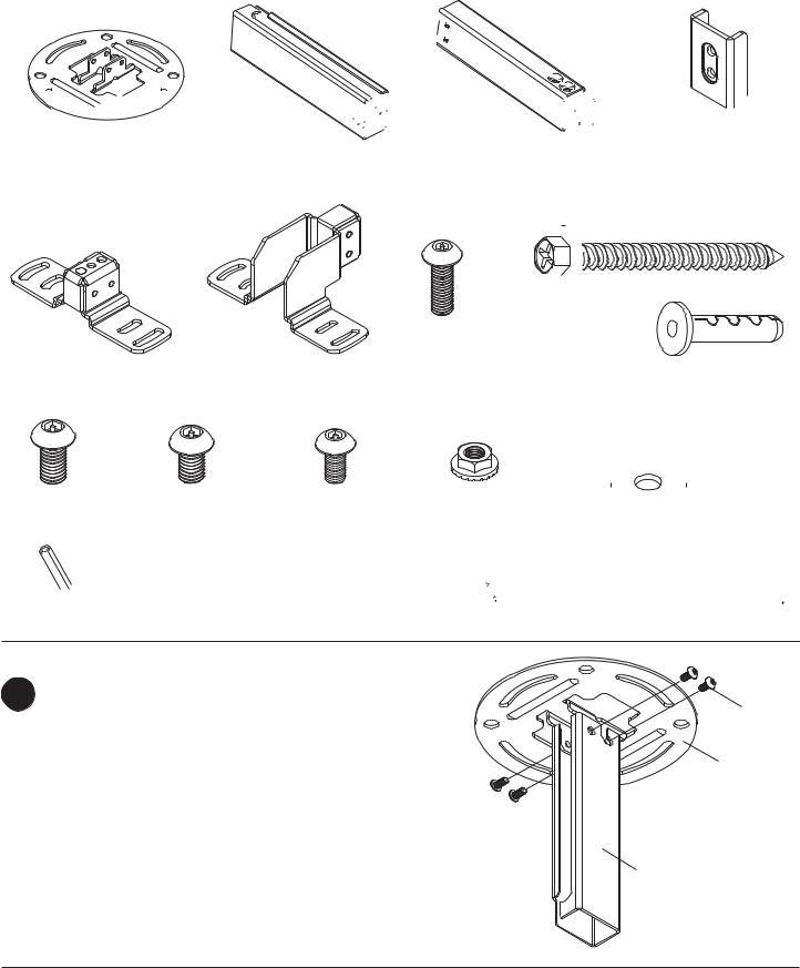
Part List Continued
Parts may appear slightly different than illustrated.
A 


 B
B 


 C
C 


 D
D 

H 


E |
F |
G |
J |
|
|
|
K L M N O
P


 Q
Q 


Install Outer Channel to Ceiling Plate
1 |
Attach outer channel (B) to ceiling plate (A) using |
four M6 x 10 mm socket pin screws (L) as shown. |
Tighten screws with security wrench (P).
L
A
B
4 of 11 |
ISSUED: 1-11-08 SHEET #: 055-9495-2 10-16-08 |
Visit the Peerless Web Site at www.peerlessmounts.com |
For customer care call 1-800-865-2112 or 708-865-8870. |
 Loading...