


XR®684F/XR®696F Operation Manual
For more information on other great Peavey products, go to your local Peavey dealer or online at www.peavey.com

Intended to alert the user to the presence of uninsulated “dangerous voltage” within the product’s enclosure that may be of sufficient magnitude to constitute a risk of electric shock to persons.
Intended to alert the user of the presence of important operating and maintenance (servicing) instructions in the literature accompanying the product.
CAUTION: Risk of electrical shock — DO NOT OPEN!
CAUTION: To reduce the risk of electric shock, do not remove cover. No user serviceable parts inside. Refer servicing to qualified service personnel.
WARNING: To prevent electrical shock or fire hazard, do not expose this appliance to rain or moisture. Before using this appliance, read the operating guide for further warnings.
Este símbolo tiene el propósito, de alertar al usuario de la presencia de “(voltaje) peligroso” sin aislamiento dentro de la caja del producto y que puede tener una magnitud suficiente como para constituir riesgo de descarga eléctrica.
Este símbolo tiene el propósito de alertar al usario de la presencia de instruccones importantes sobre la operación y mantenimiento en la información que viene con el producto.
PRECAUCION: Riesgo de descarga eléctrica ¡NO ABRIR!
PRECAUCION: Para disminuír el riesgo de descarga eléctrica, no abra la cubierta. No hay piezas útiles dentro. Deje todo mantenimiento en manos del personal técnico cualificado.
ADVERTENCIA: Para evitar descargas eléctricas o peligro de incendio, no deje expuesto a la lluvia o humedad este aparato Antes de usar este aparato, Iea más advertencias en la guía de operación.
Ce symbole est utilisé dans ce manuel pour indiquer à l’utilisateur la présence d’une tension dangereuse pouvant être d’amplitude suffisante pour constituer un risque de choc électrique.
Ce symbole est utilisé dans ce manuel pour indiquer à l’utilisateur qu’il ou qu’elle trouvera d’importantes instructions concernant l’utilisation et l’entretien de l’appareil dans le paragraphe signalé.
ATTENTION: Risques de choc électrique — NE PAS OUVRIR!
ATTENTION: Afin de réduire le risque de choc électrique, ne pas enlever le couvercle. Il ne se trouve à l’intérieur aucune pièce pouvant être reparée par l’utilisateur. Confiez I’entretien et la réparation de l’appareil à un réparateur Peavey agréé.
AVERTISSEMENT: Afin de prévenir les risques de décharge électrique ou de feu, n’exposez pas cet appareil à la pluie ou à l’humidité. Avant d’utiliser cet appareil, lisez attentivement les avertissements supplémentaires de ce manuel.
Dieses Symbol soll den Anwender vor unisolierten gefährlichen Spannungen innerhalb des Gehäuses warnen, die von Ausreichender Stärke sind, um einen elektrischen Schlag verursachen zu können.
Dieses Symbol soll den Benutzer auf wichtige Instruktionen in der Bedienungsanleitung aufmerksam machen, die Handhabung und Wartung des Produkts betreffen.
VORSICHT: Risiko — Elektrischer Schlag! Nicht öffnen!
VORSICHT: Um das Risiko eines elektrischen Schlages zu vermeiden, nicht die Abdeckung enfernen. Es befinden sich keine Teile darin, die vom Anwender repariert werden könnten. Reparaturen nur von qualifiziertem Fachpersonal durchführen lassen.
ACHTUNG: Um einen elektrischen Schlag oder Feuergefahr zu vermeiden, sollte dieses Gerät nicht dem Regen oder Feuchtigkeit ausgesetzt werden. Vor Inbetriebnahme unbedingt die Bedienungsanleitung lesen.
2

IMPORTANT SAFETY INSTRUCTIONS
WARNING: When using electrical products, basic cautions should always be followed, including the following:
1.Read these instructions.
2.Keep these instructions.
3.Heed all warnings.
4.Follow all instructions.
5.Do not use this apparatus near water.
6.Clean only with a dry cloth.
7.Do not block any of the ventilation openings. Install in accordance with manufacturer’s instructions.
8.Do not install near any heat sources such as radiators, heat registers, stoves or other apparatus (including amplifiers) that produce heat.
9.Do not defeat the safety purpose of the polarized or grounding-type plug. A polarized plug has two blades with one wider than the other. A grounding type plug has two blades and a third grounding plug. The wide blade or third prong is provided for your safety. If the provided plug does not fit into your outlet, consult an electrician for replacement of the obsolete outlet.
10.Protect the power cord from being walked on or pinched, particularly at plugs, convenience receptacles, and the point they exit from the apparatus.
11.Only use attachments/accessories provided by the manufacturer.
12.Use only with a cart, stand, tripod, bracket, or table specified by the manufacturer, or sold with the apparatus. When
a cart is used, use caution when moving the cart/apparatus combination to avoid injury from tip-over.
13.Unplug this apparatus during lightning storms or when unused for long periods of time.
14.Refer all servicing to qualified service personnel. Servicing is required when the apparatus has been damaged in any way, such as power-supply cord or plug is damaged, liquid has been spilled or objects have fallen into the apparatus, the apparatus has been exposed to rain or moisture, does not operate normally, or has been dropped.
15.Never break off the ground pin. Write for our free booklet “Shock Hazard and Grounding.” Connect only to a power supply of the type marked on the unit adjacent to the power supply cord.
16.If this product is to be mounted in an equipment rack, rear support should be provided.
17.Exposure to extremely high noise levels may cause a permanent hearing loss. Individuals vary considerably in susceptibility to noise-induced hearing loss, but nearly everyone will lose some hearing if exposed to sufficiently intense noise for a sufficient time. The U.S. Government’s Occupational and Health Administration (OSHA) has specified the following permissible noise level exposures:
Sound Level dBA, Slow Response |
Duration Per Day In Hours |
8 |
90 |
6 |
92 |
4 |
95 |
3 |
97 |
2 |
100 |
1 1/2 |
102 |
1 |
105 |
/2 |
110 |
1/4 or less |
115 |
According to OSHA, any exposure in excess of the above permissible limits could result in some hearing loss. Ear plugs or protectors to the ear canals or over the ears must be worn when operating this amplification system in order to prevent a permanent hearing loss, if exposure is in excess of the limits as set forth above. To ensure against potentially dangerous exposure to high sound pressure levels, it is recommended that all persons exposed to equipment capable of producing high sound pressure levels such as this amplification system be protected by hearing protectors while this unit is in operation.
SAVE THESE INSTRUCTIONS!
3

ENGLISH
XR® 684F/696F Powered Mixers
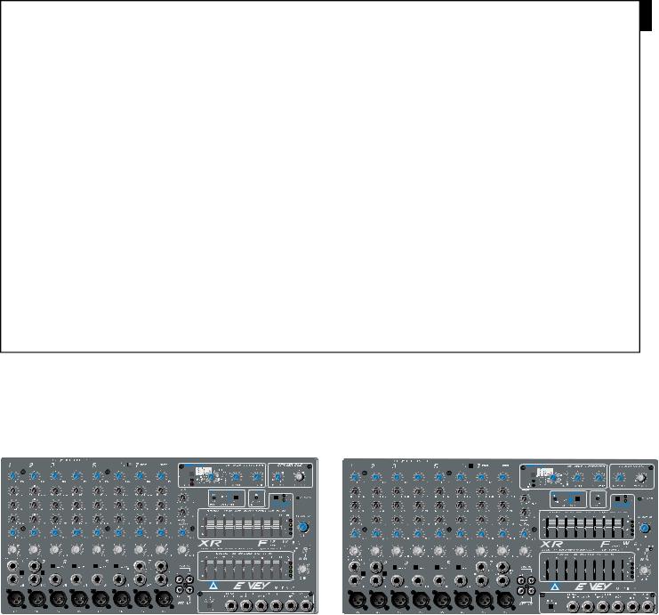
Thank you for purchasing the XR 684F/XR 696F by Peavey. These powered mixers include many of the latest technological developments from Peavey engineers. Incorporating 48-bit effects‚ a Feedback Ferret™‚ DDT™ speaker protection as well as many other features‚ this compact‚ lightweight powered mixer is perfect for most any application. More power. More features. More reliability. All from Peavey!
The XR 684F and XR 696F are both represented in this manual. Both products feature the same great innovations with the main difference being the amount of power provided. The XR 684F provides 2x200 Watts @ 4 Ohms and the XR 696F provides 2x600 Watts @ 4 Ohms. So‚ unless noted‚ the features described in this manual apply to both the XR 684F and the XR 696F.
Please read this guide carefully to ensure your personal safety as well as the safety of your equipment.
Features
•8 low-noise‚ low-Z mic preamps
•insert jacks: channels 1 and 2
•6 mono and 3 stereo line inputs
•3-band equalization: channels 1–8
•monitor sends: all channels
•effects send: channels 1–8
•25dB pad: channels 1–6
•low cut filter: channels 1–6
•built-in Feedback Ferret with blue activity indicator (LED)
•dedicated 9-band stereo EQ for stereo mains
•switchable mono EQ‚ assignable to monitor or channel 3 with LED indicators
•48-bit‚ DSP-based stereo effects with 12 presets and 4 user locations
•dual 4-segment VU meters for power amp level sensing
•48 volt phantom power
•stereo or main/monitor mode switch
•2x200 watt @ 4 ohms internal power amplifier (XR684F)
•2x600 watt @ 4 ohm internal power amplifier (XR696F)
•DDT speaker protection with activity LED
4
QUICK SET-UP GUIDE
|
|
|
|
|
|
|
|
|
|
|
|
|
|
|
|
|
|
|
|
|
|
|
|
|
|
|
|
|
|
|
|
|
|
|
|
|
|
|
|
|
|
|
|
|
|
|
|
|
|
|
|
|
|
|
|
|
|
|
|
|
|
|
|
|
|
|
|
|
|
|
|
|
|
|
|
|
|
|
|
|
|
|
|
|
|
|
|
|
|
|
|
|
|
|
|
|
|
|
|
XR 696F Front |
|
|
|
|
|
|
|
|
|
|
|
|
|
|
|
|
|
|
XR 684F Front |
||||||||||||||||||||||||||||||||||||||||||||||||||||||
|
|
|
|
|
|
|
|
|
|
|
|
|
|
|
|
|
|
|
|
|
|
|
|
|
|
|
|
|
|
|
|
|
|
|
|
|
|
|
|
|
|
|
|
|
|
|
|
|
|
|
|
|
|
|
|
|
|
|
|
|
|
|
|
|
|
|
|
|
|
|
|
|
|
|
|
|
|
|
|
|
|
|
|
|
|
|
|
|
|
|
|
|
|
|
|
|
|
|
|
|
|
|
|
|
|
|
|
|
|
|
|
|
|
|
|
|
|
|
|
|
|
|
|
|
|
|
|
|
|
|
|
|
|
|
|
|
|
|
|
|
|
|
|
|
|
|
|
|
|
|
|
|
|
|
|
|
|
|
|
|
|
|
|
|
|
|
|
|
|
|
|
|
|
|
|
|
|
|
|
|
|
|
|
|
|
|
|
|
|
|
|
|
|
|
|
|
|
|
|
|
|
|
|
|
|
|
|
|
|
|
|
|
|
|
|
|
|
|
|
|
|
|
|
|
|
|
|
|
|
|
|
|
|
|
|
|
|
|
|
|
|
|
|
|
|
|
|
|
|
|
|
|
|
|
|
|
|
|
|
|
|
|
|
|
|
|
|
|
|
|
|
|
|
|
|
|
|
|
|
|
|
|
|
|
|
|
|
|
|
|
|
|
|
|
|
|
|
|
|
|
|
|
|
|
|
|
|
|
|
|
|
|
|
|
|
|
|
|
|
|
|
|
|
|
|
|
|
|
|
|
|
|
|
|
|
|
|
|
|
|
|
|
|
|
|
|
|
|
|
|
|
|
|
|
|
|
|
|
|
|
|
|
|
|
|
|
|
|
|
|
|
|
|
|
|
|
|
|
|
|
|
|
|
|
|
|
|
|
|
|
|
|
|
|
|
|
|
|
|
|
|
|
|
|
|
|
|
|
|
|
|
|
|
|
|
|
|
|
|
|
|
|
|
|
|
|
|
|
|
|
|
|
|
|
|
|
|
|
|
|
|
|
|
|
|
|
|
|
|
|
|
|
|
|
|
|
|
|
|
|
|
|
|
|
|
|
|
|
|
|
|
|
|
|
|
|
|
|
|
|
|
|
|
|
|
|
|
|
|
|
|
|
|
|
|
|
|
|
|
|
|
|
|
|
|
|
|
|
|
|
|
|
|
|
|
|
|
|
|
|
|
|
|
|
|
|
|
|
|
|
|
|
|
|
|
|
|
|
|
|
|
|
|
|
|
|
|
|
|
|
|
|
|
|
|
|
|
|
|
|
|
|
|
|
|
|
|
|
|
|
|
|
|
|
|
|
|
|
|
|
|
|
|
|
|
|
|
|
|
|
|
|
|
|
|
|
|
|
|
|
|
|
|
|
|
|
|
|
|
|
|
|
|
|
|
|
|
|
|
|
|
|
|
|
|
|
|
|
|
|
|
|
|
|
|
|
|
|
|
|
|
|
|
|
|
|
|
|
|
|
|
|
|
|
|
|
|
|
|
|
|
|
|
|
|
|
|
|
|
|
|
|
|
|
|
|
|
|
|
|
|
|
|
|
|
|
|
|
|
|
|
|
|
|
|
|
|
|
|
|
|
|
|
|
|
|
|
|
|
|
|
|
|
|
|
|
|
|
|
|
|
|
|
|
|
|
|
|
|
|
|
|
|
|
|
|
|
|
|
|
|
|
|
|
|
|
|
|
|
|
|
|
|
|
|
|
|
|
|
|
|
|
|
|
|
|
|
|
|
|
|
|
|
|
|
|
|
|
|
|
|
|
|
|
|
|
|
|
|
|
|
|
|
|
|
|
|
|
|
|
|
|
|
|
|
|
|
|
|
|
|
|
|
|
|
|
|
|
|
|
|
|
|
|
|
|
|
|
|
|
|
|
|
|
|
|
|
|
|
|
|
|
|
|
|
|
|
|
|
|
|
|
|
|
|
|
|
|
|
|
|
|
|
|
|
|
|
|
|
|
|
|
|
|
|
|
|
|
|
|
|
|
|
|
|
|
|
|
|
|
|
|
|
|
|
|
|
|
|
|
|
|
|
|
|
|
|
|
|
|
|
|
|
|
|
|
|
|
|
|
|
|
|
|
|
|
|
|
|
|
|
|
|
|
|
|
|
|
|
|
|
|
|
|
|
|
|
|
|
|
|
|
|
|
|
|
|
|
|
|
|
|
|
|
|
|
|
|
|
|
|
|
|
|
|
|
|
|
|
|
|
|
|
|
|
|
|
|
|
|
|
|
|
|
|
|
|
|
|
|
|
|
|
|
|
|
|
|
|
|
|
|
|
|
|
|
|
|
|
|
|
|
|
|
|
|
|
|
|
|
|
|
|
|
|
|
|
|
|
|
|
|
|
|
|
|
|
|
|
|
|
|
|
|
|
|
|
|
|
|
|
|
|
|
|
|
|
|
|
|
|
|
|
|
|
|
|
|
|
|
|
|
|
|
|
|
|
|
|
|
|
|
|
|
|
|
|
|
|
|
|
|
|
|
|
|
|
|
|
|
|
|
|
|
|
|
|
|
|
|
|
|
|
|
|
|
|
|
|
|
|
|
|
|
|
|
|
|
|
|
|
|
|
|
|
|
|
|
|
|
|
|
|
|
|
|
|
|
|
|
|
|
|
|
|
|
|
|
|
|
|
|
|
|
|
|
|
|
|
|
|
|
|
|
|
|
|
|
|
|
|
|
|
|
|
|
|
|
|
|
|
|
|
|
|
|
|
|
|
|
|
|
|
|
|
|
|
|
|
|
|
|
|
|
|
|
|
|
|
|
|
|
|
|
|
|
|
|
|
|
|
|
|
|
|
|
|
|
|
|
|
|
|
|
|
|
|
|
|
|
|
|
|
|
|
|
|
|
|
|
|
|
|
|
|
|
|
|
|
|
|
|
|
|
|
|
|
|
|
|
|
|
|
|
|
|
|
|
|
|
|
|
|
|
|
|
|
|
|
|
|
|
|
|
|
|
|
|
|
|
|
|
|
|
|
|
|
|
|
|
|
|
|
|
|
|
|
|
|
|
|
|
|
|
|
|
|
|
|
|
|
|
|
|
|
|
|
|
|
|
|
|
|
|
|
|
|
|
|
|
|
|
|
|
|
|
|
|
|
|
|
|
|
|
|
|
|
|
|
|
|
|
|
|
|
|
|
|
|
|
|
|
|
|
|
|
|
|
|
|
|
|
|
|
|
|
|
|
|
|
|
|
|
|
|
|
|
|
|
|
|
|
|
|
|
|
|
|
|
|
|
|
|
|
|
|
|
|
|
|
|
|
|
|
|
|
|
|
|
|
|
|
|
|
|
|
|
|
|
|
|
|
|
|
|
|
|
|
|
|
|
|
|
|
|
|
|
|
|
|
|
|
|
|
|
|
|
|
|
|
|
|
|
|
|
|
|
|
|
|
|
|
|
|
|
|
|
|
|
|
|
|
|
|
|
|
|
|
|
|
|
|
|
|
|
|
|
|
|
|
|
|
|
|
|
|
|
|
|
|
|
|
|
|
|
|
|
|
|
|
|
|
|
|
|
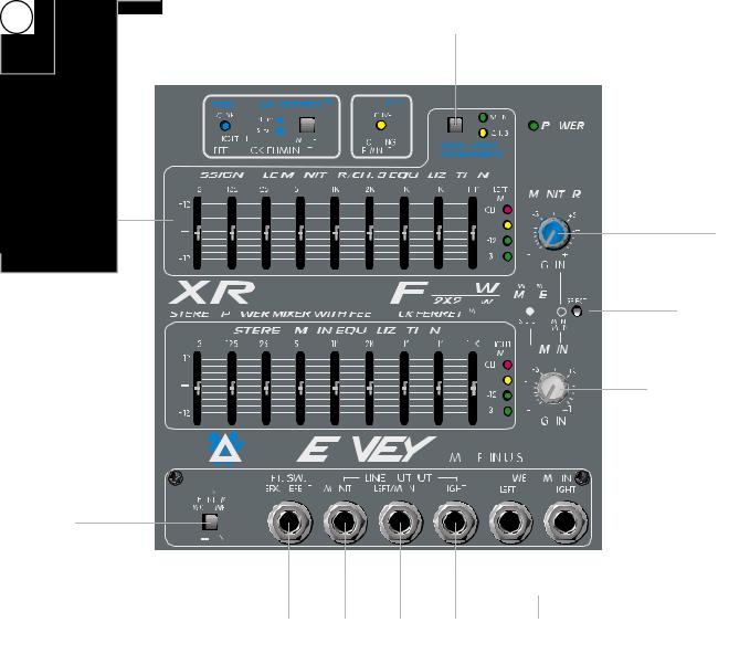
The standard channels (1–8) feature discrete‚ low-noise mic preamps with globally-switched phantom power and a 3-band EQ. Channels 1 and 2 include insert jacks (TRS). Channels 1–6 offer balanced 1/4" line-level inputs. Channels 1–6 also offer a globally-switched low-cut filter and feature a full 25 dB pad switch to accommodate a wide range of input signals. Finally‚ there are 3 stereo channels (7–9) for your tape‚ CD or synth input.
The master section features a built-in Feedback Ferret with an activity indicator (LED). The Ferret applies 16‚ 24-bit digital filters to automatically control feedback. Armed with sophisticated algorithms‚ the Ferret distinguishes between music and feedback‚ seeking and destroying the feedback. Also included in the master section is a 48-bit‚ DSP-based digital effects processor. This processor includes 16 presets‚ of which four are user presets‚ allowing you to create and store custom settings. There are also two parameter controls that allow you to set the Time/Size and Color/Tone of the effect.
5
Channel Section
Since the channel descriptions for both the XR 684F and the XR 696F are identical‚ no distinction will be made between the units in this section. Also‚ channels 7–9 contain many of the same great features found in channels 1–6 so only the differences will be pointed out on these channels (7–9).
11
10
9
8
7
6
5
4
3
2
1
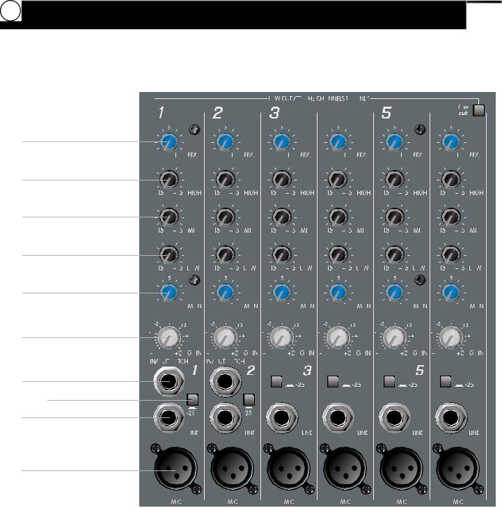
Channels 1–6
1.Mic Input: XLR balanced‚ low-impedance channel input optimized for a microphone or other low-impedance source. Pin 2 is the positive input. Due to the wide range of gain adjustment‚ signal levels as high as +10 dBV (2.45 V RMS) can be accommodated with the pad switch engaged. When the phantom power is enabled‚ this connector has +48 V on pins 2 and 3 with pin 1 as the ground reference.
2.Line Input: 1/4" balanced TRS inputs. The tip is the positive input which may also be used for unbalanced inputs. A pad switch is provided to attenuate strong signals present at this input. Note: The Mic input and the Line input cannot be used simultaneously within the same channel.
6
3.Pad: Attenuates the input signal by 25 dB. If you notice distortion from a particular channel or if the channel becomes loud very quickly‚ try engaging this switch. In addition to increasing the dynamic range‚ the channel input can now accommodate a higher input level before clipping occurs. This may be necessary when close-mic’ing a loud guitar amp or drum kit.
4.Insert Jacks (channels 1 and 2 only): 1/4" stereo (TRS) jacks which allow an external device to be inserted into the signal path before (pre) EQ. The tip carries the send signal and the ring is the return signal. A switch in the jack normally connects the send to the return until a plug is inserted. When plugged in partially (first click)‚ the jack can be used as a pre-amp output without interrupting the channel. This is a great place to insert a dedicated EQ‚ effects unit or tube preamp for an acoustic instrument or lead vocal.
5.Gain: Sets the signal level sent to the Left and Right bus.
6.Mon (monitor): Controls the level of each channel signal (pre-EQ) that is added to the monitor mix.
7.Low EQ: A shelving type of active tone control that varies the bass frequency levels (+/-15 dB at 70 Hz). This will add depth to thin-sounding signals or clean up muddy ones. As with any EQ‚ use sparingly. Too much of this EQ can give you a booming bottom end.
8.Mid EQ: A band pass (peak/notch) type of active tone control that varies the mid-range frequencies (+/-15 dB at 1 kHz).
9.High EQ: A shelving type of active tone control that varies the treble frequency (+/-15 dB at 12 kHz). This control is designed to remove noise or add brilliance to the signal depending on the quality of the source.
10.Efx: This control varies the level into the digital effects processor bus‚ adjusting signal level from the individual channel to the digital processor. It is post gain and will be affected by the gain control.
11.Low Cut: This is a low-cut filter with a corner frequency of 80 Hz. It is used to filter rumble‚ wind noise‚ stage noise and other low-frequency components that rob power from the amplifier and muddy the signal. Depressing this switch affects channels 1–6 only. It’s a great idea to engage this switch when playing outside (especially on a windy day) or in any environment with a lot of ambient noise.
7
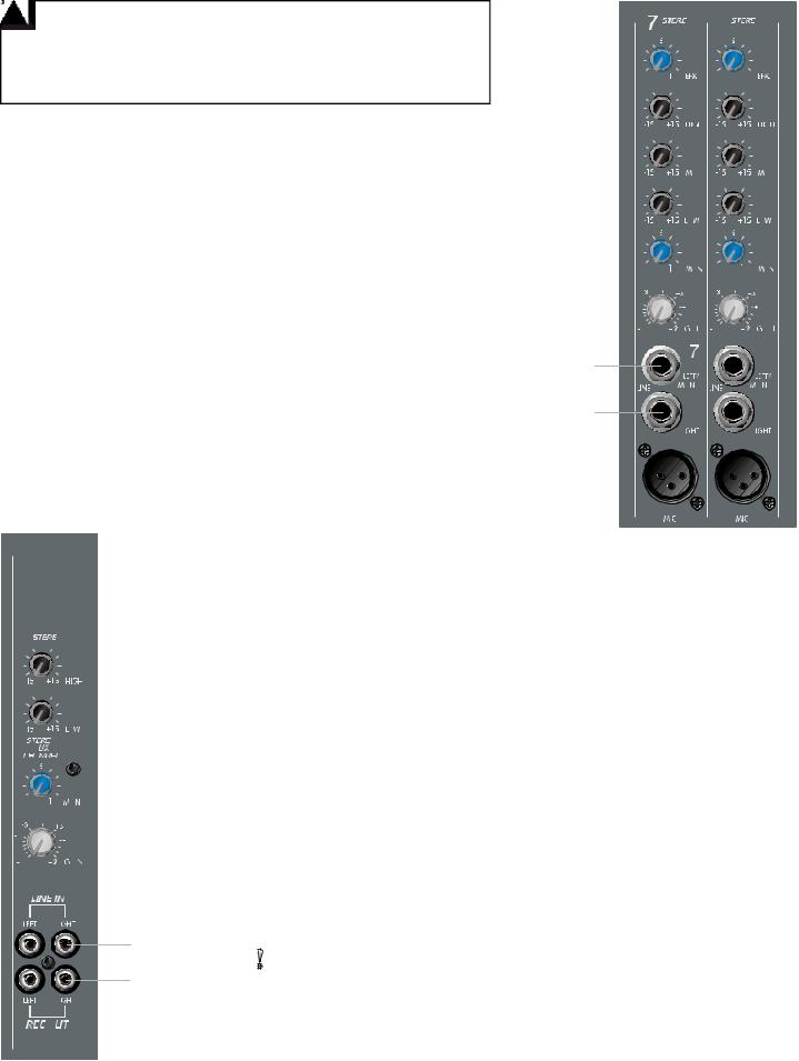
Channels 7–8
12.Right Input: High impedance 1/4" input for line-level signals. The Right Input is adjusted by the Gain control. If the XR 684F/XR 696F is in Left/Right mode‚ the signal will go the Right Speaker Output. In Main/Mon mode‚ the signal is combined with the Left Input and placed on the main speaker out. The right signal can also be patched out of the mixer via the right output jack to external components such as effects‚ power amps and recording devices.
13.Left/Mono Input: High-impedance 1/4" input for line-level signals. The Left/Mono input supplies signal to both the left and right channels if there is nothing inserted in the Right Input jack. If you’re running stereo (Left/Right mode) and are using the Right Input‚ the signal will go to the Left Speaker Output. But‚ only if you have something inserted in the Right Input jack. In Mon/Main mode‚ the signal is combined with the right and placed on the Main Speaker Output.
13 |
12 |
Channel 9
14.Line In: This stereo pair of RCA phono jacks accepts a stereo input (nominally -10 dBV) from the output of a tape deck‚ CD player or other similar device. The signal is placed on the Left and Right channels as well as the monitor mix.
15.Line Out: This stereo pair of RCA phono jacks provides a signal for the recording inputs of a stereo tape‚ CD player or other similar device.
14
15
8
Master Section
You’ll find enough features in the Master Section of the XR 684F/XR 696F to fit most sound reinforcement situations. Our audacious engineers (these guys are nuts) have been busy adding features to these products that you won’t find in any other powered mixer. A 48-bit effects processor‚ a 9-band stereo EQ‚ a Feedback Ferret™‚ DDT™ speaker protection and much more.
9

Effects Section |
|
|
|
16 |
19 |
20 |
21 |
17 |
|
|
|
18 |
22 |
23 |
16.Store: This button enables you to store a custom effects setting to one of four preset locations (Store 1–Store 4). Start with one of the twelve presets provided. Adjust the two parameter controls (Time/Size and Color/Tone) to your desired settings. When you are satisfied with the new settings‚ push the Store button once. The corresponding LED will start blinking. Now‚ twist the Preset Selector knob to one of the four locations provided and push the Store button again. This action stores your settings and the LED stops blinking. When recalling any one of these four userdefined locations‚ keep in mind that the parameter settings are stored internally and may differ from where the actual knobs are physically set.
17.Store LED: This yellow indicator blinks to indicate that you are in the Store mode. (See the above paragraph.)
18.Effects Peak LED: This red LED illuminates to indicate 6 dB of headroom before the signals being sent to the effects circuit are clipped. Ideally‚ you want this LED to light only occasionally. An occasional blink indicates that your levels are set optimally. Listen carefully to the output to determine the final setting.
10
19.Preset: Selects the effect preset or user-defined preset. See the table below.
20.Time/Size: This control adjusts the time of the particular reverb or delay and in the chorus setting it adjusts the rate of the chorus.
21.Color/Tone: This control adjusts the high frequency content of the effects signal. When using a delay setting‚ this control adjusts the feedback or depth.
22.Efx to Mon: This control adjusts the amount of effects signal sent to the monitor mix. This allows effects to be heard from the stage via the monitors.
23.Efx to Main: This controls the amount of effects signal sent to the main mix.
Feedback Ferret™ and DDT™
24.Feedback Ferret: This button controls the operation of the Feedback Ferret.
Important: To get the best performance from your new Peavey XR Powered mixer, you must let the Feedback Ferret “learn” each new room using the simple setup procedure described below.
25 |
24 |
26 |
The Ferret‚ Peavey’s award-winning feedback eliminator‚ is actually built into the XR 684F/XR 696F. The Ferret automatically applies 16 digital filters to control feedback within your setup. If you’re operating your powered mixer in stereo mode‚ you can apply the Ferret to both the Left and Right channels. If‚ on the other hand‚ you’re using your powered mixer for both Mains and Monitors‚ the Ferret can eliminate feedback from both.
To setup the Ferret‚ first make sure everything is hooked up properly—all microphones‚ speakers‚ etc. Also‚ make sure all controls are set as they will be during performance but with the Masters down. Next‚ enter the Ferret Setup mode by pushing the button (the light goes off) and holding it until the light blinks once‚ and then release. The blue LED blinks to indicate Setup mode. Now‚ slowly begin bringing the levels up to performance settings. The Ferret will automatically detect and notch the offending feedback frequencies. The Ferret will default back to Performance mode and save the settings after one minute. Or‚ you can tap the button once to return to Performance mode. If for some reason you want to bypass the Ferret‚ simply push the button and wait until it blinks a second time and then release. The LED will remain off to indicate that the Ferret is bypassed.
25.Feedback Ferret LED: This blue LED remains lit to indicate Performance mode‚ blinks to indicate Setup mode and remains off to indicate Bypass mode.
26.DDT Active LED: This yellow LED illuminates when the internal power amps reach the point when DDT is activated.
11
28
 30
30
29
27
31
32
33
34
35 |
36 |
37 |
38 |
39 |
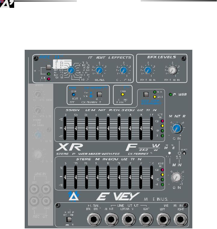
27.Graphic EQ: These 9-band EQs are fixed on one-octave centers. They are designed for 12 dB of cut or boost. The
Stereo main EQ is placed before the Preamp outputs and therefore‚ the Main preamp outputs are post-EQ.
28.EQ Assignment: This switch allows you to patch the second (top) EQ to either the Monitor or to Channel 3. The default position is the Monitor mode. This is indicated by the illuminated green LED. Push the button to change this to the Channel 3 mode and the yellow LED lights. This is a great feature to use if you have a critical instrument such as an acoustic guitar or a lead vocal. You can assign the top 9-band EQ to this channel! Although‚ keep in mind that this eliminates the EQ for your monitors.
29.Left/Right Amp Level Indicators: These LEDs illuminate to indicate at what level the internal power amps are operating. The 0 dB LED indicates that the unit is delivering the rated output power. The red LED light to alert you that the system is clipping.
30.Power LED: This LED lights when the power to the unit is on.
12

31.Monitor Level: This sets the overall level of the monitor signal that is sent to the Monitor output jack. This control also sets the monitor level going to the power amp when in Main/Mono mode.
32.Power Amp Mode: This button is used to configure the XR 684F/XR 696F as either a stereo or dual mono amplifier. It is recessed to prevent accidental switching. Use a non-metallic object to change the switch position (e.g.‚ a toothpick). The unit is shipped from the factory in the default stereo setting (Left to the first power amp and Right to the second). The two internal Feedback Ferret channels are assigned to the Left and Right outputs. When this switch is depressed‚ the first power amp is assigned to the Monitors and the second amplifier now becomes a mono Main (Left and Right combined). In this setting‚ one channel of the Ferret is assigned to the Monitor and one channel is assigned to the Main signal. Note that when this switch is depressed‚ the Left and Right preamp out jacks as well as the Right/Main power amp out are now mono. They are also post Feedback Ferret #1 and the Monitor out jack is now post Feedback Ferret #2.
33.Main Level: This is the master level control for the Main mix sent to the Left/Mono and Right output jacks and their corresponding power amplifiers. This also controls the Main level going to the power amp when in the Main/Mono mode.
34.Phantom Power Switch: This switch‚ when depressed‚ applies 48 VDC to all input XLR connectors to power microphones that require phantom power.
Caution: When phantom power is switched on‚ make sure that any channel you are plugging a microphone into is turned down and the Master Main and Monitor controls are set to minimum. Otherwise‚ there will be a loud pop in the system. It is best to first plug in all microphones into their respective channels before phantom power is switched on. This reduces noise through the system and reduces the chance of damage to the microphones. If phantom power is used‚ do not connect unbalanced‚ dynamic microphones or other devices to the XLR inputs that cannot handle this voltage. (Some wireless receivers may be damaged. Consult their manuals.) The line input jacks are not connected to the phantom supply and are safe for all inputs (balanced or unbalanced). An unbalanced to balanced impedance converter such as the Peavey 5116 or a Peavey 1:1 Interface Adapter may also be used to isolate a microphone from phantom voltage.
35.Effects Footswitch: This 1/4" jack accepts an on/off 1/4" footswitch (Peavey Part # 00051000) to defeat effects of both the Main and Monitor mixes.
36.Monitor Output: This 1/4" jack provides an output from the monitor mix to supply external power amplifier/monitor combinations. The level of this signal is determined by the Monitor Level control. Note that when the mode switch is in the Main/Mono mode‚ the monitor signal passes through the Feedback Ferret. This output is post EQ‚ depending on the EQ assignment switch.
37.Left/Mono Output: This 1/4" jack provides an output from the Left Main mix to supply external amplifier/speaker combinations. The level of this signal is determined by the Main level control. When no plug is connected to the Right Output‚ the right signal is mixed with the left and both can be accessed at the Left/Mono Output. This works well when you use the internal amplifiers for monitor and external amplifiers for the mains. This output is post EQ and post Feedback Ferret.
38.Right Output: This 1/4" jack provides output from the Right Main mix to supply external amplifier/speaker combinations. The level of this signal is determined by the Main level control. This output is post EQ and post Feedback Ferret. Note that in Main/Mono mode‚ this output is the same as Left/Mono output.
39.Power Amp Inputs: Plugging into these jacks allows the user to go directly to the respective power amplifier channel and therefore bypass the other functions of the mixer.
13
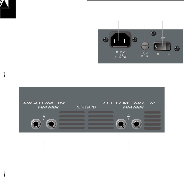
AC Power and Power Amplifier Section
40. |
AC Power Inlet: This is the receptacle for the supplied |
40 |
|
42 |
41 |
|
|
IEC line cord. This provides AC power to the unit. |
|
|
|
|
|
|
Connect the supplied line cord to this connector to |
|
|
|
|
|
|
provide power to the unit. Damage to the equipment |
|
|
|
|
|
|
may result if improper line voltage is used (see line |
|
|
|
|
|
|
|
|
|
|
|
|
|
voltage markings on the unit). |
|
|
|
|
|
|
|
|
|
|
|
|
|
|
|
|
|
|
|
41. |
Power: The main power switch for the XR 684F/ |
|
|
|
|
|
|
XR 696F. The power on LED indicator will light when the |
|
|
|
|
|
|
unit is powered. |
|
|
|
|
|
42.Fuse: This is the main safety fuse for the AC line voltage. Only replace with a fuse of the exact type and rating. If
the fuse continues to open‚ do not over fuse. Take the unit to an authorized Peavey service center.
43 |
43 |
43.Left/Mon Right/Main Speaker Outputs: These 1⁄4" jacks are the amplifier’s outputs. By connecting a speaker cable to these jacks and to a speaker cabinet‚ you complete the signal chain. You will notice there are two pairs of jacks. The
two pairs are your two (stereo) amplifier outputs. Two cabinets can be connected to each channel as long as the combined impedance of the cabinets is not less than 4 ohms. (i.e.‚ two 8 ohm cabinets in parallel = 4 ohms‚ four 16 ohm cabinets in parallel = 4 ohms‚ etc.)
14
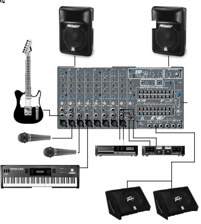
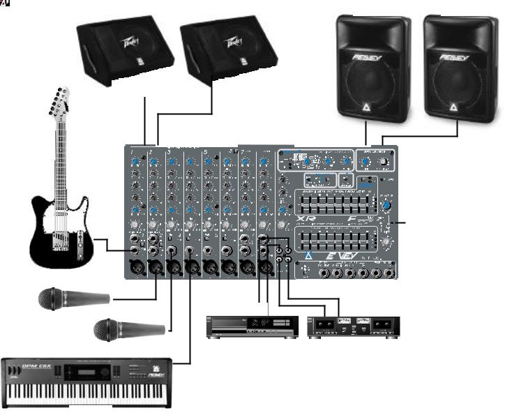
XR 684F/XR 696F Hookup Diagrams
The following hookup diagrams are only suggestions. These powered mixers provide enough flexibility for a variety of needs. Just use common sense when hooking up your equipment. When in doubt‚ consult your authorized Peavey dealer.
XR 684F/XR 696F Stereo Mode (Left/Right)
15
XR 684F/XR 696F Monitor/Main Mode
16

XR®684F/XR®696F · Technical Specifications
XR 684F/XR 696F · Input Specifications:
Function |
Input Z |
Input Gain Control |
|
Input Levels |
|
Bal |
Connector |
|
|
(ohms) Min |
Settings |
Min** |
Nominal* |
Max |
Unbal |
|
|
|
|
|
|
|
|
|
|
|
Lo-Z Mic (150 Ohms) |
2 k |
Max w/o pad |
-59dBu |
-29dBu |
|
-11dBu |
Bal |
XLR Pin 1 Gnd |
|
|
(50dB) |
-34dBu |
-4dBu |
|
+14dBu |
|
Pin 2 (+) |
|
|
Max w/pad (25dB) |
|
|
|
|
|
Pin 3(-) |
Line Input |
22 k |
Max w/o pad |
-27dBu |
+2dBu |
|
+21dBu |
Unbal |
1⁄4" TRS; Tip (+) |
|
|
(30dB) |
-2dBu |
+27dBu |
|
+46dBu |
|
Ring (-) |
|
|
Max w/pad (5dB) |
|
|
|
|
|
Sleeve Gnd |
Tape |
20 k |
Max gain (30dB) |
-26dBu |
+4dBu |
|
+21dBu |
Unbal |
RCA jacks |
|
|
|
|
|
|
|
|
|
0dBU = 0.775V (RMS)
** Minimum input level (sensitivity) is the smallest signal that will produce nominal output (4dBu) with channel and master controls set for maximum gain.
* Nominal settings are defined as all controls set at 0dB (or 50% rotation for rotary pots)
XR 684F/XR 696F · Output Specifications:
Function |
Minimum Load Z (ohms) |
|
Output Level |
Bal |
Connector |
|
|
|
Nominal |
|
Max |
Unbal |
|
Main L/R |
600 |
+4dBu |
|
+15dBu |
Unbal |
1/4" Phono Tip (+) |
|
|
|
|
|
|
Sleeve Ground |
Monitor |
600 |
+4dBu |
|
+15dBu |
Unbal |
1/4" Tip (+) |
|
|
|
|
|
|
Sleeve Ground |
Tape |
10k |
+4dBu |
|
+14dBu |
Unbal |
RCA |
|
|
|
|
|
|
|
+2dBU = 0dBV = 1V (RMS)
17

XR 684F/XR 696F · Hum and Noise:
Output |
Residual Noise |
Test Conditions |
|
Ref: 4dBu |
|
Main L/R |
-90 dB |
All controls down |
|
-87 dB |
1 channel nominal‚ Master nominal |
|
-81 dB |
Master Fader Nominal‚ Channel Faders Nominal‚ Mic Inputs Terminated @ 150 Ohms |
Monitor |
-90 dB |
All controls down |
|
-90 dB |
1 channel nominal‚ Master nominal |
|
-82 dB |
Master Fader Nominal‚ Channel Faders Nominal‚ Mic Inputs Terminated @ 150 Ohms |
|
|
|
(Hum and Noise measurements: 22 Hz–22 kHz BW)
18
19
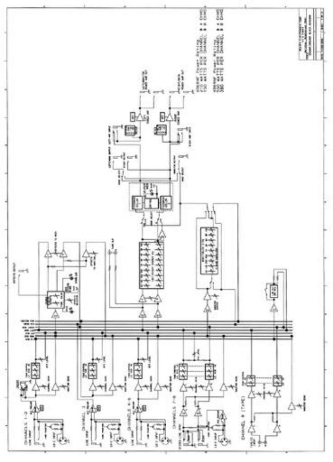
XR684F/XR696F Block Diagram
20
 Loading...