


 ®
®
O W N E R ’ S M A N U A L

Intended to alert the user to the presence of uninsulated “dangerous voltage” within the product’s enclosure that may be of sufficient magnitude to constitute a risk of electric shock to persons.
Intended to alert the user of the presence of important operating and maintenance (servicing) instructions in the literature accompanying the product.
CAUTION: Risk of electrical shock — DO NOT OPEN!
CAUTION: To reduce the risk of electric shock, do not remove cover. No user serviceable parts inside. Refer servicing to qualified service personnel.
WARNING: To prevent electrical shock or fire hazard, do not expose this appliance to rain or moisture. Before using this appliance, read the operating guide for further warnings.

ENGLISH
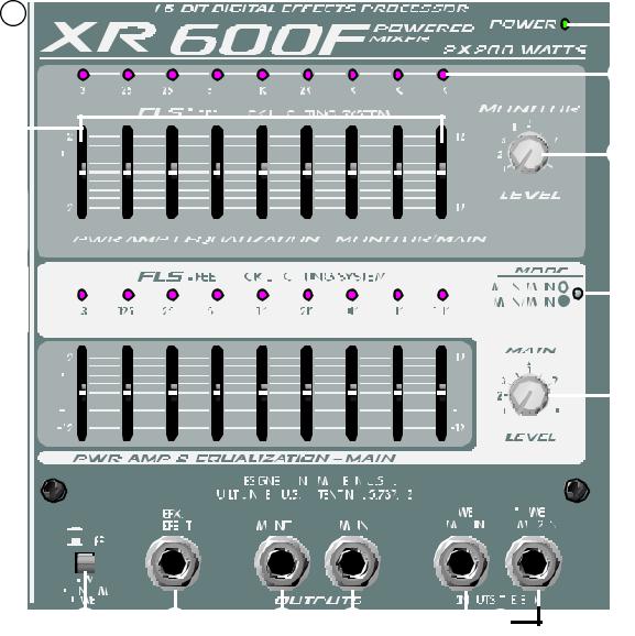
XR™ 600F Powered Sound Reinforcement Mixing Console
General Description:
Congratulations on your purchase of the XR™ 600F powered mixer. Within one compact unit, we have packed feature after feature, each displaying the latest technology available. Here are several features you will certainly want to notice:
•Six low-noise, low-Z mic preamps
•Four true high-Z 1/4" mic inputs
•Three-band equalization (Channels 1-6)
•Monitor send (each channel)
•EFX send (Channels 1-6)
•-25 dB pad (Channels 1-4)
•16-bit, DSP-based stereo reverb/delay with two parameter controls
•Two nine-band graphic EQs with FLS® Feedback Locating System®
•48 V phantom power
•Main/Monitor mode switch
•2x200 W @ 4 ohms internal power amplifier
•420 W @ 8 ohms in bridge mode
•DDT™ speaker protection
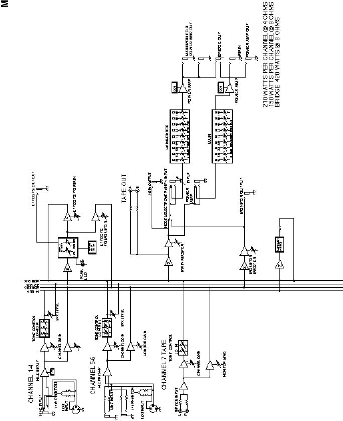
The standard channels (1-4) feature discrete low noise mic preamps with globally switched phantom power, true high-impedance 1/4" mic inputs, low-cut filters, and three-band EQs. Two additional channels (5-6) offer balanced XLR mic inputs and dual 1/4" line level inputs. Finally, channel 7 offers dual RCA jacks for summing stereo outputs (from tape, CD, etc.) into mono.
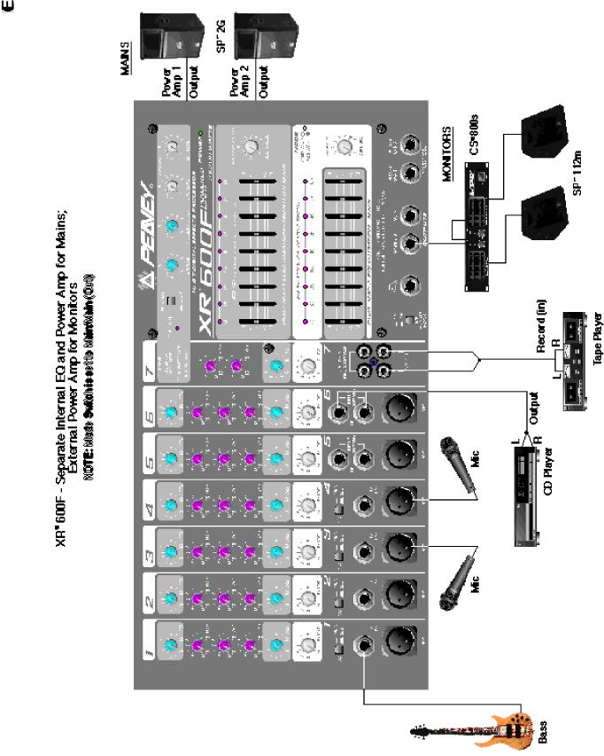
The master section features a unique graphic equalizer/power amp mode switch. Without patching, the XR 600F can be used as a mixer/amplifier for the mains (default). This mode utilizes both EQ’s and both channels of the amplifier to supply a left and right speaker (mains). In the Main/Monitor mode, one graphic and amplifier can be used for monitor and the other graphic and amplifier for the main signal.
Also included in the master section are two digital effects (reverb and delay) from the award winning Deltafex™ digital signal processor. By including separate Size/Time and Color/Feedback controls, the user can create many effect settings from the two we provided. All channels, except channel 7, have a dedicated digital effects send routed directly to the DSP effects processor.
To take advantage of the XR 600F’s powerful features, please read this owner’s manual carefully and keep it as a reference. This manual includes several sections detailing individual areas of mixer operation, including: control functions, set-up, and applications in sound reinforcement.

CHANNEL SECTION:
CHANNELS 1-4
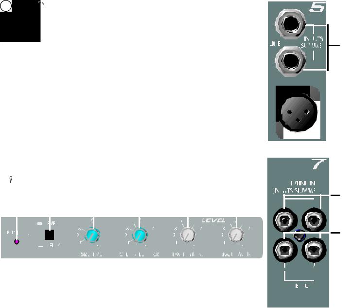
1.MIC INPUT: XLR balanced, low-impedance channel input optimized for a microphone or other low-level source. Pin 2 is the positive input. Because of the wide range of gain adjustment, signal levels as high as +10 dBV (2.45 V RMS) can be accommodated. When the phantom power is enabled, this connector has +48 V on pins 2 and 3 with pin 1 as the ground reference. (The Mic Input can also be found on channels 5 and 6.)
2.HI-Z/LINE INPUT: 1/4" balanced TRS high-impedance input. The tip is the positive input, which can also be used for unbalanced inputs. A Pad (#3) switch is provided to attenuate strong signals present at this input. Within the same channel, the mic input and the Hi-Z/Line input cannot be used simultaneously.
3.PAD: Attenuates the input signal by 25 dB. If you find that barely touching the Level control (#4) gives you an enormous increase in volume or if distortion occurs, try using the Pad switch. In addition to increasing the dynamic range, the channel input can now accommodate a higher input level before clipping. This may be necessary with a close mic on loud guitar amplifiers or drum kits.
4.LEVEL: Sets the signal level sent to the Main bus. (The level control can also be found on channels 5 through 7.)
5.MON: Adjusts the level of the channel signal (pre-EQ) that is added to the Monitor mix. (The Monitor control can also be found on channels 5 through 7.) This control is independent of the main channel level control (#4).
6.LOW EQ: A shelving type of active tone control that varies the bass frequency levels ±15 dB at 70 Hz. It will add depth to thin signals, or clean up muddy ones. (The low control can also be found on channels 5 through 7.)
7.MID EQ: Mid ±15 dB. This control sets the amount of cut and boost at the mid-frequency (850 Hz). (The mid control can also be found on channels
5through 6.)
8.HIGH EQ: A shelving type of active tone control that varies the treble frequency levels ±15 dB at 12 kHz. It is designed to remove noise or to add brilliance to the signal, depending on the quality of the source. (The high control can also be found on channels 5 through 7.)
9.EFX: This control varies the level into the digital effects processor bus adjusting the signal level from the particular channel to the digital processor. (The effects control can also be found on channels 5 and 6.) The channel level control (#4) also affects this level.
NOTE: Channels 5-7 contain features that differ from the previous channels. Only those features are mentioned below. For information on features not mentioned please refer to the section for Channels 1-4.
9
8
7
6
5
4
3
2
1
CHANNELS 5-6
10. LINE INPUTS (Dual Summed): 1/4" unbalanced inputs for line level signals. Ideal for stereo outputs from midi sound modules and/or stereo audio equipment, this input sums (mixes) two inputs (L/R) into one. However, it is not limited to stereo combining. It is possible to insert the outputs of two keyboards into these jacks, thus mixing them into one combined signal. In this case, balance of the two signals would be controlled by the keyboard’s level control. This signal is connected through a 25 dB pad to the mic input below it. Use of the mic input allows channels 5 and 6 to duplicate channels 1-4.
CHANNEL 7
11.TAPE/LINE IN: This stereo RCA phono jack accepts a stereo input (nominally -10 dBV) from the output of a tape deck or CD player and sums the Left and Right channels into a mono signal found in the Main Mix and Monitor Mix. These jacks can also be used as line inputs such as those found on channels 5 and 6.
12.TAPE OUT: This stereo RCA phono jack provides a signal for the recording inputs of a stereo tape deck.
CAUTION: DO NOT HOOK THE TAPE IN AND TAPE OUT TO THE INPUT AND OUTPUT OF THE SAME DECK. DOING SO WILL FORM A LOOP 
 CAUSING SEVERE FEEDBACK. USE SEPERATE DECKS FOR RECORDING AND PLAYBACK.
13 |
14 |
|
|
|
15 |
16 |
17 |
18 |
|
|
|
|
|
|
|
|
|
|
|
|
|
|
|
|
|
|
|
|
|
|
|
|
|
|
|
|
|
|
|
|
|
|
|
|
|
|
|
|
|
|
|
|
|
|
|
|
|
|
|
|
|
|
|
|
|
|
|
|
|
|
|
|
|
|
|
|
|
|
|
MASTER SECTION:
13.EFFECTS PEAK LED: Illuminates to indicate -6 dB of headroom before the signals being sent to the effects circuit are clipped. Ideally, you would want this LED to light only occassionally if at all. An occassional blink indicates that you have the levels at an optimum setting. It is advisable to listen carefully to the output at the same time in order to determine the final setting.
14.REVERB/DELAY SWITCH: Selects the type of effect; Reverb or Delay.
15.SIZE/TIME: This control adjusts the time of the reverb or delay.
16.COLOR/FEEDBACK: Adjusts the high-frequency content of the effects signal. (While using the delay this control adjusts the feedback or depth.)
17.EFX TO MON: Controls the amount of effects signal sent to the monitor mix. This control allows effects to be heard from the stage via the monitor.
10
11
12
18. EFX TO MAIN: Controls the amount of effects signal sent to the main mix.
29
19
20
22
21
23
24 |
25 |
26 |
27 |
|
28 |
|
19.FLS ® (Feedback Locating System® ): These LEDs illuminate to indicate the frequency band of highest energy. When feedback occurs, this system will automatically indicate the graphics slider to use to decrease that frequency band’s gain in order to lessen or eliminate feedback. (NOTE: These LEDs illuminate with any audio signal, not just during feedback.)
20.GRAPHIC EQUALIZERS: These nine-band equalizers are fixed on one-octave centers. They are designed for 12 dB of cut and 12 dB boost. They are connected directly to their power amplifier inputs.
21.SYSTEM MODE: This switch is used to configure the XR 600F as a dual mono amplifier for two main outputs or one main and one monitor output. It is recessed to prevent accidental switching during a performance. Use a non-metallic object to change the switch position (e.g., a toothpick). The XR 600F is shipped from the factory in the default setting of Main/Main (both amplifiers carry the same signal from the main bus). When this switch is depressed the lower EQ / PWR AMP 2 remains connected to the main bus (mono). The upper EQ / PWR AMP 1 then carries the monitor signal only, creating an entire PA and monitor mixing system in one small, easy-to-carry package. And this change is accomplished without a single patch cord!
22.MONITOR LEVEL: Sets the overall level of the monitor signal that is sent to the Monitor Output Jack. This control also sets the monitor level going to the power amp when in Main/Monitor mode (see System Mode #21).
23.MAIN LEVEL: This is the master level control for the main mix and main output jack. This control sets the Main level going to the power amp when in Main/Monitor mode and also in the Main/Main mode (see System Mode #21). A good starting position for this control is the center detent position (12:00).

24. PHANTOM POWER SWITCH: Applies 48 V DC voltage to all input XLR connectors to power microphones that require it.
CAUTION! When phantom power is switched on, make sure that any channel you are plugging a mic into is turned down in both the main and monitor mixes. Otherwise, there will be a loud pop in the PA. This is  normal. It is best to plug all mics into their respective channels with the phantom power switched off.
This reduces noise in the PA and reduces the chances of the mic being damaged. If phantom power is used, do not connect unbalanced microphones or other devices that cannot handle this voltage to the XLR inputs. (Some wireless receivers may be damaged; consult their manuals for compatibility.) The line input 1/4" jacks are not connected to the phantom supply, and are safe for all inputs (balanced or unbalanced). An unbalanced-to-balanced impedance converter, such as the Peavey 5116 or a Peavey 1:1 Interface Adapter, can also be used to isolate a mic from phantom voltage.
25.EFX DEFEAT: This 1/4" jack accepts an on/off 1/4" footswitch (Peavey Part #00051000) to defeat the effects of both the Main and Monitor mixes.
26.MONITOR OUTPUT: This 1/4" jack provides an output from the monitor mix to supply external power amp/monitor combinations. The level of this signal is determined by the Monitor Level control.
27.MAIN OUTPUT: This 1/4" jack provides an output from the Main mix to supply external amp/speaker combinations. The level of this signal is determined by the Main Level control.
28.POWER AMP INPUTS: Plugging into these jacks allows the user to go directly into the Graphic Equalizer, then into its respective power amplifier channel.
29.POWER LED: The power on LED indicator will light when the unit is powered.
AC POWER AND POWER AMPLIFIER SECTION:
30. A/C POWER INLET: This is the receptacle for an IEC line cord, |
30 |
32 |
31 |
which provides AC power to the mixer/amplifier. Connect the line cord |
|||
to this connector to provide power to the unit. Damage to the equipment |
|
|
|
may result if improper line voltage is used (see line voltage marking |
|
|
|
on unit). |
|
|
|
31. POWER: The mixer’s main power switch. The power on LED |
|
|
|
indicator (#29) will light when the unit is powered. |
|
|
|
32. FUSE: This is the main safety fuse for the AC line voltage. Only replace the fuse with one the exact same type and rating. IF THE FUSE CONTINUES TO OPEN, DO NOT OVER FUSE. TAKE THE UNIT TO AN AUTHORIZED PEAVEY SERVICE CENTER!
33. PARALLEL LEFT/RIGHT SPEAKER OUTPUTS: These 1/4" jacks |
|
|
|
are the amplifier’s output. By connecting a speaker cable to this |
|
|
|
jack and to a speaker cabinet, you complete the signal chain. |
|
|
|
You will notice that there are two pairs of jacks with another jack in the |
|
|
|
middle. The two pairs are your two (stereo) amp outputs. |
|
|
|
Multiple cabinets can be connected to each channel, as long as the |
|
|
|
combined impedance of the cabinets is not less than 4 ohms (i.e., two |
|
|
|
8 ohms cabinets in parallel = 4 ohms, four 16 ohms speakers in parallel |
|
|
|
= 4 ohms, etc.). |
33 |
34 |
33 |
34. BRIDGE OUTPUT: The bridge output of the XR 600F allows the power of the left and right amplifiers to be combined into one mono output in applications where only one speaker will be used. To use the bridge output, the system mode switch must be in the Main/Main position. Connect an 8 ohm minimum impedance speaker to the center bridge output jack.
CAUTION: When using the bridge output no other speakers should be connected to the adjacent parallel speaker outputs. In addition, the minimum load for the XR 600F in bridge mode is 8 ohms. Do not allow the total imped-  ance to drop below 8 ohms or serious damage to the amplifier may occur.
 Loading...