


TR A N S CH O R U S™ 210
Operating Guide
Intended to alert the user to the presence of uninsulated “dangerous voltage” within the product’s enclosure that may be of sufficient magnitude to constitute a risk of electric shock to persons.
Intended to alert the user of the presence of important operating and maintenance (servicing) instructions in the literature accompanying the product.
CAUTION: Risk of electrical shock — DO NOT OPEN!
CAUTION: To reduce the risk of electric shock, do not remove cover. No user serviceable parts inside. Refer servicing to qualified service personnel.
WARNING: To prevent electrical shock or fire hazard, do not expose this appliance to rain or moisture. Before using this appliance, read the operating guide for further warnings.
Este símbolo tiene el propósito, de alertar al usuario de la presencia de “(voltaje) peligroso” que no tiene aislamiento dentro de la caja del producto que puede tener una magnitud suficiente como para constituir riesgo de corrientazo.
Este símbolo tiene el propósito de alertar al usario de la presencia de instruccones importantes sobre la operación y mantenimiento en la literatura que viene con el producto.
PRECAUCION: Riesgo de corrientazo — ¡No abra!
PRECAUCION: Para disminuír el riesgo de corrientazo, no abra la cubierta. No hay piezas adentro que el usario pueda reparar. Deje todo mantenimiento a los técnicos calificados.
ADVERTENCIA: Para evitar corrientazos o peligro de incendio, no deje expuesto a la lluvia o humedad este aparato Antes de usar este aparato, Iea más advertencias en la guía de operación.
Ce symbole est utilisé pour indiquer à l’utilisateur la présence à l’intérieur de ce produit de tension nonisolée dangereuse pouvant être d’intensité suffisante pour constituer un risque de choc électrique.
Ce symbole est utilisé pour indiquer à l’utilisateur qu’il ou qu’elle trouvera d’importantes instructions sur l’utilisation et l’entretien (service) de l’appareil dans la littérature accompagnant le produit.
ATTENTION: Risques de choc électrique — NE PAS OUVRIR!
ATTENTION: Afin de réduire le risque de choc électrique, ne pas enlever le couvercle. Il ne se trouve à l’intérieur aucune pièce pouvant être reparée par l’utilisateur. Confier I’entretien à un personnel qualifié.
AVERTISSEMENT: Afin de prévenir les risques de décharge électrique ou de feu, n’exposez pas cet appareil à la pluie ou à l’humidité. Avant d’utiliser cet appareil, lisez les avertissements supplémentaires situés dans le guide.
Dieses Symbol soll den Anwender vor unisolierten gefährlichen Spannungen innerhalb des Gehäuses warnen, die von Ausreichender Stärke sind, um einen elektrischen Schlag verursachen zu können.
Dieses Symbol soll den Benutzer auf wichtige Instruktionen in der Bedienungsanleitung aufmerksam machen, die Handhabung und Wartung des Produkts betreffen.
VORSICHT: Risiko — Elektrischer Schlag! Nicht öffnen!
VORSICHT: Um das Risiko eines elektrischen Schlages zu vermeiden, nicht die Abdeckung enfernen. Es befinden sich keine Teile darin, die vom Anwender repariert werden könnten. Reparaturen nur von qualifiziertem Fachpersonal durchführen lassen.
ACHTUNG: Um einen elektrischen Schlag oder Feuergefahr zu vermeiden, sollte dieses Gerät nicht dem Regen oder Feuchtigkeit ausgesetzt werden. Vor Inbetriebnahme unbedingt die Bedienungsanleitung lesen.
2
ENGLISH
Congratulations on your purchase of combines Peavey’s patented design. If you haven’t played Transtube® technology produces a experienced ears. Peavey’s chorus of chorus sounds varying from a
Other features found on the
amp, two sets of equalization, and compact 210 cabinet, and you have ing various playing demands. We Start” section and a “Recommended However, it is important that you locate these safety icons:
Each safety icon is followed by a you have read all of the warnings, recommended that you read this feature.
The following section takes a “jump confusing, refer to the more detailed
Step 1. Insure that you have read manual. It is imperative that you
Step 2. With the amp turned on the back of the unit near
Step 3. Plug your guitar into either to their “0” position.
Step 4. Using the “Recommended resembles the tone you wish to
Step 5. Set the knobs on the front of
Step 6. Plug your footswitch into the
Step 7. Turn your guitar volume the unit.
Step 8. Gradually turn the volume of the level/tone.
™ 210. The TransChorus™ 210 the latest developments in chorus
amp you are in for a real treat. that it’s deceiving to even the most
sellers for years, offering an array
three distinct channels, stereo power power amp circuitry. Pack all that into a versatile combo-amp capable of answerstart playing, so we’ve included a “Quick
are certain to get you on your way. first. Scan through this manual and
carefully before continuing on. Once section below if you so desire. It is
understand the functions of each
to play!
approach. If any part seems
warnings noted throughout the
the safety of yourself and your amp.
into the proper voltage supply indicated
and turn all knobs counter clockwise
the type of tone that most closely
setting you have selected.
the rear of the unit.
using the power switch on the back of
up or until you are comfortable with
3
Step 9. Experiment with the footswitch to get familiar with how the three different channels are selected.
Note: The Select button on the amp must be pressed (down position) in order for the footswitch to work.
Step 10. To adjust the overall level of each channel, use the Volume knob for the Clean channel and the Post Gain controls for the Crunch and Lead channels.
Step 11. To adjust the amount of distortion in the Crunch and Lead channels, use the Pre Gain knob. Turning the knob clockwise results in increased distortion.
Step 12. You should be able to play at this time. Push the various buttons to hear their effect on your tone. Vary the Reverb or Chorus Rate and Depth knobs to get a feel for their effect as well. Most importantly....READ THE REST OF THIS MANUAL.
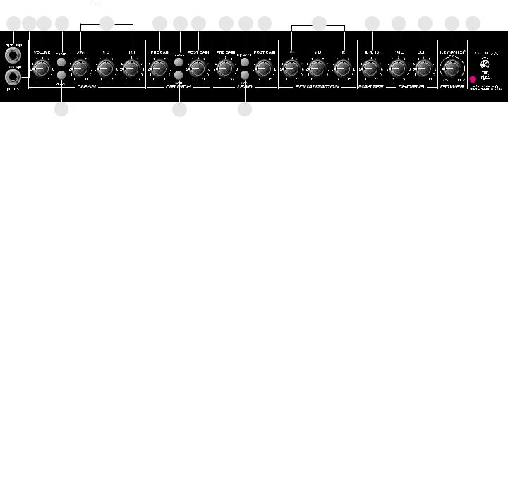
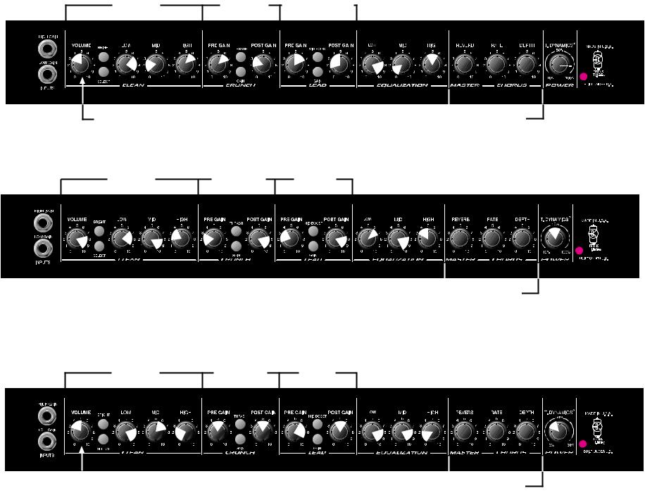
FRONT PANEL
1 2
9 |
13 |
Input (1)
Used for most electric guitars. It is 6 dB louder than the Low Gain input.
Low Gain (2)
Provided for instruments that have extremely high outputs, which can result in overdriving (distortthe High Gain input. If both inputs are used simultaneously, the output levels are the same (both
gain).
Clean Channel
Volume (3)
Controls the output level of the Clean channel.
Bright Switch (4)
When activated (pressed in), this switch provides a 6 dB boost to the extreme high frequency portion of your signal.
Select Switch (5)
This switch selects between the Clean and Lead channels. The “in” position selects the Lead channel and the “out” position selects the Clean. Channel selection may also be achieved by using the remote footswitch. The Select Switch must be in the “in” position for the footswitch to operate. Use of the footswitch will also allow you to select between the Crunch and Lead channels.
Low, Mid, and High EQ (6)
This section is a passive tone control for the clean channel. Adjusting these knobs clockwise will pass more low, mid, or high frequency content of the Clean channel to the internal power amps.
4
Crunch Channel Pregain (7)
Controls the input level of the Crunch channel. Adjusting this control clockwise will increase the input level, thus increasing distortion.
Thrash Switch (8)
When activated (in), this switch attenuates a preset portion of the mid range resulting in a more “heavy” sound and an apparent increase in distortion.
Gain Switch (9)
When activated (in), this switch boosts the pregain of the Crunch channel resulting in increased distortion. This effect is often used to get intentional feedback and increased sustain.
Post Gain (10)
Controls the output level of the Crunch channel. Adjusting this control clockwise will result in increased volume. The desired tone and distortion level should be obtained prior to adjusting this control for proper level. Consider this control the volume control for the Crunch channel.
Lead Channel
Pregain (11)
Controls the input level of the Lead channel. Adjusting this control clockwise will increase the input level, thus increasing distortion.
Mid Boost Switch (12)
When activated (in), this switch boosts the mid frequencies. This effect is often desired when miking an amp that is producing distorted guitar signals. Selecting the Mid Boost will bring the signal up in the overall mix during lead passages.
Gain Switch (13)
When activated (in), this switch boosts the pregain of the Lead channel resulting in increased distortion. This effect is often used to get intentional feedback and increased sustain.
Post Gain (14)
Controls the output level of the Lead channel. Adjusting this control clockwise will result in increased volume. The desired tone and distortion level should be obtained prior to adjusting this control for proper level. Consider this control the volume control for the Lead channel.
Low, Mid, and High EQ (15)
This section is a passive tone control for the Crunch and Lead channels. Adjusting these knobs clockwise will pass more low, mid, or high frequency content of these to the internal power amps .
Reverb (16)
Adjusting this control clockwise will result in more reverb content in the output of the amp regardless of the channel. The reverb can be defeated completely by rotating the control counter clockwise.
Rate (17)
Adjusting this control clockwise will result in an increase in the sweep rate (frequency) of the chorus effect. The chorus can only be disabled from the footswitch.
5
Depth (18)
Adjusting this control clockwise will result in an increase in the depth or intensity of the chorus effect. This control adjusts the amount of chorus you actually hear from the output of the amp.
T. Dynamics® (19)
This control adjusts the usable power of the internal power amps from 10% (counter clockwise) to 100% (clockwise). Rotating this control clockwise will result in more available power. This effect is often set to lower levels in order for the power amp compression simulation to be more apparent, allowing you to overdrive the power amp at lower volume levels, achieving a tube power amp clipping/compression quality.
Power LED (20)
Illuminates when power is supplied to the amp. If this LED is lit, the amp is on.
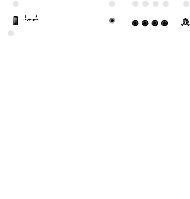
REAR PANEL
22 |
23 |
24 |
23 |
24 |
25 |
||
|
|
|
|
|
|
|
|
|
|
|
|
|
|
|
|
|
|
|
|
|
|
|
|
|
|
|
|
|
|
|
|
|
|
|
|
|
|
|
|
26
Power Switch (21)
Placing switch in the “ON” position will result in power being supplied to the unit. The Power LED (20) illuminate when the amp is on.
Stereo Headphone (22)
This 1/4” |
output jack is designed to accommodate standard, stereo headphones. Plugging |
a set of |
into this jack will disconnect the signal going to the power amplifiers of the |
unit, and |
output can be heard from the unit’s speakers. This feature provides an excellent |
practice |
. |
Power Amp In (23) |
|
These |
right mono 1/4" jacks provide an input to each of the power amplifiers. When used |
in conjunction with the Preamp Out jacks (24), a stereo effects loop is formed allowing the use
of stereo |
and various effects. |
Preamp |
(24) |
These |
right mono 1/4" jacks provide an output from each of the preamps. When used |
in conjunction with the Power Amp In jacks (23), a stereo effects loop is formed allowing the use
of stereo |
and various effects. |
Remote |
(25) |
This jack |
provided for the connection of the supplied footswitch. The footswitch is a multi-function |
type allowing you to select Clean, Crunch, or Lead and to defeat the Chorus effects. To use the
footswitch |
that the footswitch plug is inserted fully into the jack and that the Select switch is |
pressed |
(down position) on the front panel. |
6

AC LINE CORD—120 V PRODUCTS ONLY (26)
For you safety, we have incorporated a three-wire line (mains) cable with proper grounding facilities. It is not advisable to remove the ground pin under any circumstances. If it is
necessary to use the equipment without proper grounding facilities, suitable grounding adapters should be used. Less noise and greatly reduced shock hazard exists when the unit is operated with the proper grounded receptacles.
NOTE: FOR UK ONLY
As the colors of the wires in the mains lead of this apparatus may not correspond with the colored markings identifying the terminals in your plug, proceed as follows:
•The wire which is colored green and yellow must be connected to the terminal which is marked by the letter E, or by the earth symbol, or colored green or green and yellow.
•The wire which is colored blue must be connected to the terminal which is marked with the letter N, or the color black.
•The wire which is colored brown must be connected to the terminal which is marked with the letter L, or the color red.
7
8
|
|
MODERATE |
CLEAN |
METAL |
DISTORTION |
In |
|
|
|
|
|
In |
|
|
In |
|
|
||||
In |
|
In |
|
Out |
|
||
To Taste
CLEAN |
RHYTHM |
LEAD |
BLUES |
BLUES |
BLUES |
Out |
Out |
In |
In |
Out |
Out |
JAZZ |
JAZZ |
JAZZ |
CLEAN |
RHYTHM |
LEAD |
In |
Out |
In |
In 


 Out
Out 


 In
In
 To Taste
 To Taste
SETTINGS: RECOMMENDED
|
To Taste |
|
To Taste |
|
|
TRANSCHORUS™ 210 SPECIFICATIONS
(ALL MEASUREMENTS @ 120 V AC, 60HZ)
POWER AMPLIFIER SECTION
RATED OUTPUT POWER:
Power specs measured with T. Dynamics @ 100% (5% THD, 1 kHz, 120 V AC)
50 W RMS per channel, into 8 ohms
FREQUENCY RESPONSE:
Stereo mode into 8 ohm, power amp inputs
-3 dB, +2 dB, 70 Hz to 20 kHz, @ 45 W RMS into 8 ohms
HUM AND NOISE:
Unweighted, 20 Hz to 22 kHz
Greater than 90 dB, both channels
POWER CONSUMPTION:
Domestic Model: 120 V AC, 60 Hz, 2.5A, 300 W Export Model: 220 to 240 V AC, 50/60 Hz, 300 W
PREAMP SECTION
(The following specs are measured @ 1 kHz with the controls preset as follows:)
Push Bright, off (out) Channel Select Clean (out) Low and High @ 10
Mid @ 0
Crunch Pre and Post Gain @ 10 Gain and Thrash, off (out)
Lead Pre and Post Gain @ 10 Gain and Mid Boost, off (out)
Normal levels are with normal volume @ 5 Minimum levels are with clean volume @ 10
PREAMP HIGH GAIN INPUT:
Impedance: High-Z, 1 M ohm
Nominal Input Level: -12 dBV, 250 mV RMS Minimum Input Level: -22 dBV, 79 mV RMS Maximum Input level: 0 dBV, 1 V RMS
PREAMP LOW GAIN INPUT:
Impedance: High-Z, 44 k ohms
Nominal Input Level: -6 dBV, 500 mV RMS Minimum Input Level: -16 dBV, 158 mV RMS Maximum Input level: 6 dBV, 2 V RMS
PREAMP OUTPUT:
Load Impedance: 300 ohm or greater Nominal Output Level: 0 dBV, 1 V RMS
POWER AMP INPUT:
Impedance: High-Z, 30 k ohms Designed Input Level: 0 dBV, 1 V RMS
(Switching jack provides preamp output to power amp input connection when not used.)
SYSTEM HUM AND NOISE @ NOMINAL INPUT LEVEL
UNWEIGHTED, 20 Hz to 22 kHz
Greater than 75 dB, below rated power
EQUALIZATION:
Special low, mid and high passive type EQ Push Bright: +4 dBV @ 2 kHz, (Clean channel)
Push Thrash: -6 dBV notch 1 kHz, (Crunch channel) Push Mid boost: +3 dBV band pass 1 kHz, (Lead channel) Push Gain: Increase gain both Lead and Crunch channels
EXTERNAL FOOT SWITCH FUNCTIONS:
Lead/Crunch: Selects lead or crunch channel. Bypass/Clean: Lead and Crunch channel defeat (channel switch “IN”)
Select/Chorus: Defeat Chorus
DIMENSIONS AND WEIGHT (H x W x D):
18.5" x 23.375" x 11.375" 47cm x 10.60cm x 29cm
9
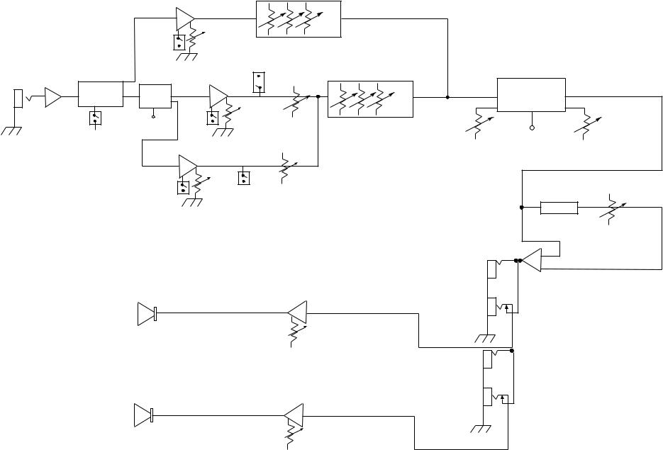
TransChorus™ 210 BLOCK DIAGRAM
1st INPUTS GAIN STAGE
SWITCH LOGIC
CLEAN/ULTRA
PUSH
CHANNEL
FOOT
SWITCH
10
|
|
|
TONE |
|
|
|
CLEAN |
|
|
|
|
|
|
|
VOLUME |
|
|
|
|
|
|
CLEAN |
|
|
|
|
|
PUSH |
|
LO |
MID |
HI |
|
|
BRIGHT |
|
|
|
|||
|
|
PUSH |
|
|
|
|
|
|
MID |
|
|
|
|
|
|
BOOST |
|
|
|
|
|
HIGH |
|
POST |
|
EQUALIZATION |
|
|
|
|
|
|
||
SWITCH |
GAIN AMP |
|
|
|
||
LEAD |
|
|
|
|
STEREO |
|
LOGIC |
|
|
|
|
|
CHORUS |
LEAD |
PUSH |
PREGAIN |
|
|
|
|
|
|
|
|
|
||
FOOT |
BRIGHT |
LEAD |
LEAD |
LOW |
MID |
HIGH |
SWITCH |
|
|
|
|
|
|
|
FOOT |
|
RATE |
SWITCH |
DEPTH |
|
POST
CRUNCH |
|
PREGAIN |
PUSH |
|
THRASH |
PREGAIN |
CRUNCH |
|
REVERB |
|
LEVEL |
|
PREGAIN |
|
OUT |
PREGAIN
SPEAKER POWER AMP IN
AMP
T. DYNAMICS®
PREGAIN
OUT
PREGAIN
AMP IN
SPEAKER |
POWER |
|
AMP |
T. DYNAMICS®
 Loading...