


S R C ® S e ri e s
18, 26 and 34 Channel Stereo Mixing Consoles
®
O WNER |
’S M ANUAL |

|
|
Intended to alert the user to the presence |
of uninsulated "dangerous voltage" within the product's enclosure |
|
|
|
that may be of sufficient magnitude to constitute a risk of electric shock to persons. |
||
|
|
Intended to alert the user of the presence of important operating and maintenance (servicing) instructions in the |
||
|
|
literature accompanying the product. |
|
|
|
CAUTION: |
Risk of electrical shock – DO NOT |
OPEN! |
|
|
CAUTION: |
To reduce the risk of electric shock, do not remove cover. No user serviceable parts inside. Refer servicing to |
||
|
qualified service personnel. |
|
|
|
|
|
|
|
|
|
WARNING: |
To prevent electrical shock or fire hazard, do not expose this appliance to rain or moisture. Before using this |
||
|
appliance, read the operating guide for further warnings. |
|
|
|
|
|
|
|
|
Este símbolo |
tiene el propósito de alertar al usuario de la presencia de |
"(voltaje) peligroso" que no tiene |
|
aislamiento dentro de la caja del producto que puede tener una magnitud suficiente como |
para constituir riesgo de |
||
corrientazo. |
|
|
|
Este símbolo |
tiene el propósito de alertar al usario de la presencia de instruccones |
importantes sobre la |
operación |
y mantenimiento en la literatura que viene con el producto. |
|
|
|
PRECAUCION: |
Riesgo de corrientazo – No abra. |
|
|
PRECAUCION: |
Para disminuír el riesgo de corrientazo, no abra la cubierta. No hay piezas adentro que |
el usario pueda |
|
reparar. Deje todo mantenimiento a los técnicos calificados.
ADVERTENCIA: Para evitar corrientazos o peligro de incendio, no deje expuesto a la lluvia o humedad este aparato
Antes de usar este aparato, lea más advertencias en la guía de operación.
|
Ce |
symbole est |
utilisé pur |
indiquer |
à |
l'utilisateur |
la |
présence à l'intérieur de ce pr |
|
oduit |
de tension |
non-isolée |
|||||||
|
dangereuse pouvant être d'intensité suf |
|
|
|
|
fisante pour constituer un risque de choc électrique. |
|
|
|
|
|||||||||
|
Ce |
symbole est utilisé pour indiquer |
à |
l'utilisateur |
qu'il |
ou |
qu'elle |
tr |
|
ouvera d'importantes |
instructions |
sur |
|||||||
|
l'utilisation et l'entretien (service) de l'appareil dans la littérature accompagnant le produit. |
|
|
|
|
|
|||||||||||||
|
ATTENTION: |
Risques de choc électrique – NE P |
|
AS OUVRIR! |
|
|
|
|
|
|
|||||||||
|
ATTENTION: |
Afin de réduire le risque |
de |
choc électrique, ne |
pas |
enlever le |
couvercle. Il ne se trouve à |
|
|
l'intérieur |
|||||||||
|
aucune pièce pouvant être réparée par l'utilisateur |
|
|
|
|
. Confier l'entretien à un personnel qualifié. |
|
|
|
|
|||||||||
|
|
|
|
|
|
|
|
|
|
|
|||||||||
|
AVERTISSEMENT: |
|
Afin de prévenir |
les |
risques de décharge électrique |
ou de feu, n'exposez pas |
cet appareil à la pluie |
|
|
|
|||||||||
|
ou à l'humidité. Avant |
d'utiliser |
cet appareil, |
lisez |
les |
avertissements |
supplémentaires situés |
dans le |
guide. |
|
|
|
|||||||
|
|
|
|
|
|
|
|
|
|
|
|
|
|
|
|
|
|
|
|
Dieses Symbol soll den Anwender vor unisolierten gefährlichen Spannungen innerhalb des Gehäuses warnen, die von Ausreichender Stärke sind, um einen elektrischen Schlag verursachen zu können.
|
Dieses Symbol soll den Benutzer auf wichtige Instruktionen |
in der Bedienungsanleitung aufmerksam machen, die |
|
Handhabung undWartung des Produkts betref |
fen. |
VORSICHT: |
Risiko – Elektrischer Schlag! Nicht öf |
fnen! |
VORSICHT: |
Um das Risiko eines elektrischen Schlages zu vermeiden, nicht die Abdeckung enfernen. Es befinden sich |
|
keine Teile darin, die vom Anwender repariert werden könnten. |
Reparaturen nur von qualifiziertem Fachpersonal |
|
durchführen lassen. |
|
|
ACHTUNG: Um einen elektrischen Schlag oder Feuergefahr zu vermeiden, sollte dieses Gerät nicht dem Regen oder
Feuchtigkeit ausgesetzt werden.Vor Inbetriebnahme unbedingt die Bedienungsanleitung lesen.
Page 2

|
SRC |
® 4018 FC, 4026 FC and 4034 FC |
The SRC |
® 4026 FC, 4034 FC and 4018 FC are versatile four-bus consoles in 18, 26 and 34 channel |
|
versions, built into road-worthy cases. Designed for sound reinforcement applications, they can also be used in multitrack recording.
The standard channels feature discrete low-noise mic preamps with globally-switched 48V phantom
power, low-cut filters, and four-band EQs. There are six auxiliary sends (four dedicated pre-EQ for monitor sends, two switchable pre-EQ/post-fader for monitor or effect sends), as well as bus assign (L/R, 1/2, 3/4), mute and PFL switches. The PFL logic automatically shifts the L/R meters to the PFL signal when any PFL button is pressed to assist in input gain adjustment and operates even when the channel
is muted. The mute circuitry squelches all sends from the channel, including all auxiliary sends and bus sends.
Two “super” mic channels also have pad and polarity switches for those applications that require it, as well as the standard channel functions. There are no line inputs on these channels. In addition to the mic channels, there are two stereo (line level) channels for tape, CD or synth inputs. These have all the standard channel functions except low-cut filters. AUX 5 and AUX 6 on these channels are
configured for stereo (AUX 5 is Left, AUX 6 is Right) and are pre-EQ/post-fader switchable.
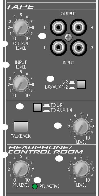
There are four fully-assignable stereo returns with PFL and mute, two of which have treble and bass controls. They can be used for effect returns or for additional stereo inputs. A dual function headphone/control-room level control sets the volume of the headphones and the output level at the control room output jacks. RCA type stereo tape inputs and outputs are provided, with sends to the
main L/R mix and the AUX 1 and 2 (monitor) mixes. A talkback mic input can be also be assigned to the main mix or to AUX 1-4 for announcements or stage communication.
All bus summing amps are designed with discrete transistor circuitry for low noise operation. A unique gain structure gives an additional 6 dB channel fader and summing amp headroom over other designs.
The Left, Right, and four sub-mix master outputs each have LED meters. They are calibrated for a 0 dB reading at a +4 dBu output level. A balanced mono output (derived from the post fader Left and Right outputs) has its own level control. Each channel, stereo return, and master AUX send has an overload LED indicator that illuminates when the signal level is within 2 dB of clipping or when the PFL switch is activated. Electronic muting of the AUX and the Left and Right outputs greatly reduce any turn on and turn off transients.
Two lamp connectors are provided for Peavey ML |
™ -2 or ML ™ -3 flexible lamps to illuminate the console |
in dark environments. |
|
Page 3
|
|
|
|
Channel Functions |
|
|
|
|
|
|
|||
1 |
|
|
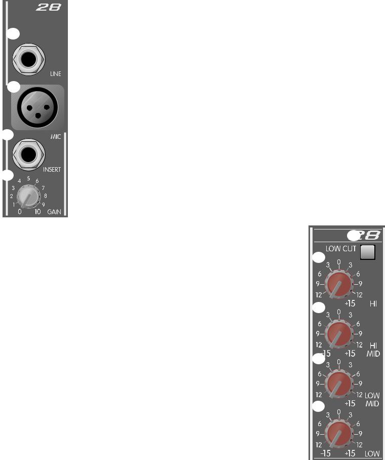
1. |
Line Input |
||
|
|
|
|
1/4" balanced (TRS) high-impedance input for high-level signals. The tip is the |
||
|
|
|
|
|
||
|
|
|
|
|
positive input, which should also be used for unbalanced inputs. This input is |
|
|
|
|
|
|
connected through a 10 dB pad to the Mic Input (#2). The two inputs cannot |
|
|
|
|
|
|
be used simultaneously. |
|
|
|
|
2. |
Mic Input |
||
2 |
|
|
|
|
XLR balanced low-impedance channel input optimized for a microphone or other |
|
|
|
|
||||
|
|
|
|
|
low-level source. Pin 2 is the positive input. Because of the wide range of gain |
|
|
|
|
|
|
adjustment, signal levels as high as +10 dBu (2.45 V RMS) can be accommodated. |
|
|
|
|
|
|
This connector has 48V on pins 2 and 3 (pin 1 is the ground reference) when |
|
|
|
|
|
|
the phantom power is enabled. (See note on #23.) |
|
3. Insert
3
1/4" stereo (TRS) jack allows an external device to be inserted into the signal path before the EQ. The tip has the send signal, the ring is the return input. A
switch in the jack normally connects the send to the return until a plug is inserted.
4. |
Gain |
|||||||
4 |
|
|
|
|
|
|
|
Varies the input gain to allow for a wide dynamic range. Proper adjustment of the |
|
|
|
|
|
|
|
||
|
|
|
|
|
|
|
|
input gain will maximize the signal-to-noise ratio. It should be set by depressing |
|
|
|
|
|
|
|
|
|
|
|
|
|
|
|
|
|
the PFL switch (#18) and adjusting for a 0 dB (+4 dBu) level at the L-R meters. |
|
|
|
|
|
|
|
|
|
5
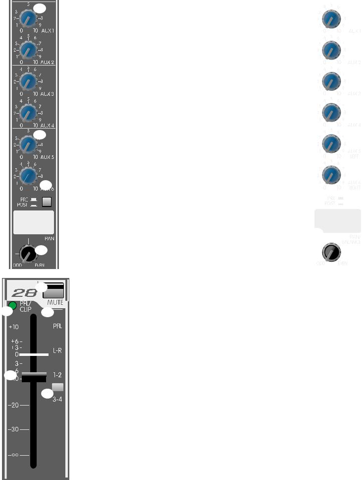
This is a low-cut filter with a corner frequency of 75 Hz used to filter out rumble, wind noise, breath thumps, stage noise and other low-frequency components
that rob power from the amplifiers and muddy the signal. The pre-EQ signals sent to the AUX sends are picked up after this switch so that the monitors can also benefit from this filter.
6. Hi EQ
A shelving type of active tone control that varies the treble frequency levels
±15 dB at 12 kHz. It is designed to remove noise or to add brilliance to the signal, depending on the quality of the source.
7.Hi/Mid EQ
A bandpass (peak/notch) type of active tone control that varies the upper mid-
range frequency levels ±15 dB at 3.1 kHz. This frequency is optimum for bringing out the clarity of a vocal mic without adding harshness or grit, or can reduce high frequency feedback.
8.Low/Mid EQ
A bandpass (peak/notch) type of active tone control that varies the lower mid-
range frequency levels ±15 dB at 250 Hz. A slight cut in this frequency will usually help a mic that has a proximity effect to become more intelligible in close talking situations. It will also be useful to solve common feedback problems.
9. Low EQ
A shelving type of active tone control that varies the bass frequency levels ±15 dB at 70 Hz. It will add depth to thin signals or clean up muddy ones.
5
6
7 

8
9

Page 4


 10
10

 11
11

 12
12


 13
13


 17
17
16 |
18 |
|
|||||
|
|||||||
|
|
|
|
|
|
|
|
|
|
|
|
|
|
|
|
|
|
|
|
|
|
|
|
|
|
|
|
|
|
|
|
|
|
|
|
|
|
|
|
|
|
|
|
|
|
|
|
|
|
|
|
|
|
|
|
|
|
|
|
|
|
|
|
|
|
|
|
|
|
|
|
|
|
|
|
|
|
|
|
|
|
|
|
|
|
|
|
20
19 
|
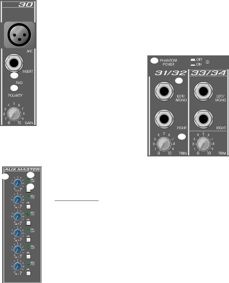
Adjusts the level of the channel signal (pre-EQ) that is added to |
|
|
|
|
|
|
|
|
|
|
|
|
|
|
|
|
|
|
|
|
|
|
|
|
|
|
|
the corresponding AUX mix. These are designed to be used for |
|
|
|
|
|
|
monitor sends. |
|
|
|
|
|
|
|
|
|
|
|
|
11. |
AUX 5/AUX 6 |
|
|
|
|
|
|
|
|
|
|
||
|
Adjusts the level of the channel signal that is added to the |
|
|
|
|
|
|
corresponding AUX mix. These are selectable Preor Post-EQ |
|
|
|
|
|
|
|
|
|
|
|
|
|
Fader (#12) on all channels, and are configured in stereo |
|
|
|
|
|
|
|
|
|
|
|
|
|
|
|
|
|
|
|
|
(AUX 5=L, AUX 6=R) on the two stereo channels. They can be |
|
|
|
|
|
|
used as a stereo pair to drive stereo effect units. (See #14) |
|
|
|
|
|
12. |
Pre/Post Fader |
|
|
|
|
|
|
|
|
|
|
||
|
Establishes which signal will be present on the AUX 5 and |
|
|
|
|
|
|
AUX6 sends (#11). The out position picks up the signal after the |
|
|
|
|
|
|
|
14 |
|
|
||
|
picks up the signal after the Channel Fader (#20). |
|
|
|
||
|
|
|
||||
|
|
|
|
|
|
|
|
|
|
|
|
|
|
13. |
Pan |
|
|
|
|
|
|
Sets the channel’s position in one or more stereo fields |
|
|
|
|
|
|
|
|
|
|
|
|
|
determined by the selection of the Assignment Switches (#19). |
|
|
|
|
|
|
|
|
|
|
|
|
|
|
|
|
|
|
|
14. Stereo Channel AUX Sends |
|
|
|
|
|
|
|
AUX 1-AUX 4 sends are a mono mix of the left and right signals. |
|
|
|
|
|
|
AUX 5 and AUX 6 are configured for stereo operation |
|
|
|
|
|
|
(AUX 5=L, AUX 6=R) on these channels. |
|
|
|
|
|
15. |
Balance |
|
|
|
|
|
|
Adjusts the balance of the stereo signal that is sent to the |
15 |
|
|
|
|
|
assignment select switches. Functions as a pan control for |
|
|
|
|
|
|
|
|
|
|
|
|
|
mono signals. (See #24) |
|
|
|
|
|
|
|
|
|
|
|
|
|
|
|
|
|
|
|
16. PFL/Clip LED
A dual-function LED that illuminates when the signal level is nearing the overload point, or if the PFL switch is engaged. This circuit monitors the input gain,
that gain or EQ boost should be reduced. (There is roughly 2 dB of headroom remaining when it lights.) When the PFL switch (#18) is depressed, it lights continuously to indicate that this channel has been assigned to the PFL mix.
17. Mute
Mutes the entire channel (all bus assignments and all AUX sends). The PFL signal is not affected, and can be used to adjust the channel’s level while muted.
18. PFL
Connects the channel’s pre-fader signal to the PFL mix and switches the headphone/control room source from the L-R mix to the PFL mix. It also connects the PFL signal to the L-R meters to aid in the setting the input gain (#4). The
PFL/Clip LED (#16) will light when this switch is pressed to identify the PFL source.
19. Assignment Switches
Selects the channel’s bus assignments (L-R, 1-2, 3-4) in pairs. The stereo postion of the signal in the selected pair is determined by the Pan control (#13).
20. Channel Fader
Channel output level control. Sets the level sent to the Assign Switches (#19). The optimum setting for this control is the “0” (unity gain) position.
Page 5
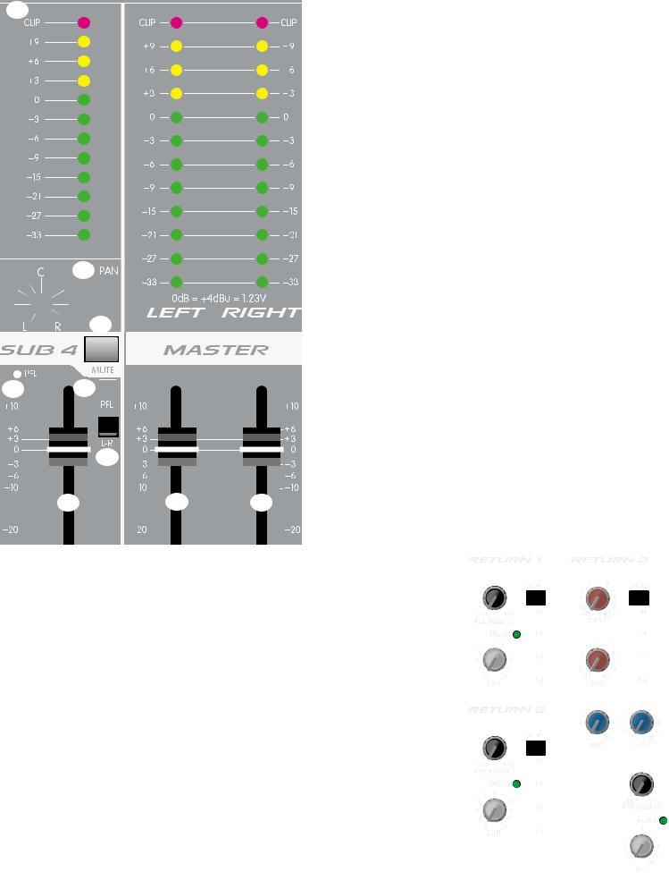
21. Pad
Attenuates the input signal by 10 dB. This will increase the dynamic range to accommodate a higher input level before clipping which may be necessary when close miking loud guitar amplifiers or drum kits.
22. Polarity
Reverses the polarity of the input signal. This will compensate for an out-of-phase input that would otherwise cause frequency cancellations in the mix. (Often needed for drum mics where both sides of the drum head are picked up in multiple microphone
situations.)
|
|
|
|
|
|
|
|
|
|
23 |
|
|
|
|
|
21 |
|
|
|
|
|
nectors to power microphones that require it. |
|
|
|
|
|
||||
|
|
|
|
|
|
|
|||||||||
|
|||||||||||||||
|
|
|
|
|
|
|
|
|
|
|
|
||||
|
|
|
|
|
unbalanced dynamic microphones or other |
24 |
|
|
|||||||
|
|
|
|
|
|
|
|
|
|
|
|||||
|
|
|
|
|
|
|
|
|
|
|
|||||
22 |
|
|
|
|
|
devices to the XLR inputs that cannot handle |
|||||||||
|
|
|
|
|
|
|
|
|
this voltage. (Some wireless receivers may |
||||||
|
|
|
|
|
|
|
|
|
be damaged, consult their manuals.) The |
||||||
|
|
|
|
|
|
|
|
||||||||
|
|
|
|
|
|
|
|
|
Line Input jacks (#1) are not connected to the |
||||||
|
|
|
|
|
|
|
|
||||||||
|
|
|
|
|
|
|
|
|
48V supply, and are safe for all inputs (balanced |
||||||
|
|
|
|
|
|
|
|
|
or unbalanced). An unbalanced-to-balanced |
||||||
|
|
|
|
|
|
|
|
||||||||
|
|
|
|
|
|
|
|
|
impedance converter such as the Peavey |
5116 |
|
|
|
|
|
|
|
|
|
|
|
|
|
|
or 7201 (female XLR), or a Peavey 1:1 interface |
||||||
|
|
|
|
|
also be used to isolate the mic input from 48V. Phantom |
|
|
|
|
|
|
||||
|
|
|
|
|
|
|
25 |
|
|||||||
|
|
|
|
not available at the talk back mic connector. |
|
|
|
|
|||||||
|
|
|
|
|
|
||||||||||
|
|
|
|
|
|
|
|
|
|
||||||
Input
input for line-level signals. The left/mono input to both the left and right inputs if there is nothing
the right input jack.
|
25. |
Trim |
26 |
27 |
|
|
|
|
|
28 |
maximize the signal-to-noise ratio, and can be set using the PFL |
|
|
switch. (See #4) |
|
Master Functions |
|
|
26. |
AUX Master Level |
|
|
Sets the overall level of the AUX signal that is sent to the output jack. (See #49) |
|
27. |
AUX PFL/Clip |
|
|
A dual function LED that illuminates when the signal level is nearing the over- |
|
|
load point, or if the PFL switch is engaged. It illuminates at +19 dBu. (There |
|
|
is roughly 2 dB of headroom remaining when it lights.) When the AUX PFL |
|
|
switch (#28) is depressed, it lights continuously to indicate that this AUX has |
|
|
been assigned to the PFL mix. |
|
28. |
AUX PFL |
|
|
Connects the AUX signal (pre-master level) to the PFL mix and switches the |
|
|
headphone/control room source from the L-R mix to the PFL mix. It also |
|
|
connects the PFL signal to the L-R meters to aid in monitoring the output level. |
Page 6
29
30
32
and the main L-R outputs. The 0 dB reference level corresponds to +4 dBu. The L-R meter array is also used for PFL metering.
(See #18, 28 and 33)
30. Sub Pan
Sets the position of the sub mix in the L-R stereo field.
31. Sub PFL LED
Illuminates when the Sub PFL switch (#33) is depressed to indicate that this signal has been assigned to the PFL mix.
32. Sub Mute
Mutes the sub mix signal to the sub output and to the L-R mix. It does not affect the PFL signal, which can be used to check the levels when the sub mix is muted.
33. Sub PFL
Connects the sub signal (pre-master level) to the PFL mix and switches the headphone/control room source from the L-R mix
to the PFL mix. It also connects the PFL mix signal to the L-R meters. (See #32.)
34. Sub L-R assign
Assigns the sub mix to the L-R mix with its stereo position determined by the Sub Pan control (#30).
31 |
33 |
|
|
|
|
|
|
|
|
|
|
|
|
Sub mix output level control. Sets the level sent to the output |
||
|
|
|
|
|
|
|
|
|
|
|
|
|||||
|
|
|
|
|
|
|
|
|
|
|
|
|
|
|
|
jack and the L-R assign switch (#34). The optimum setting for |
|
|
|
|
|
|
|
|
|
|
|
|
|
|
|
|
|
|
|
|
|
|
|
|
|
|
|
|
|
|
|
|
|
|
|
|
|
|
|
|
|
|
|
|
|
|
|
|
|
|
this control is the “0” (unity gain) position. |
|
|
|
|
|
|
|
|
|
|
|
|
|
|
|
|
|
|
|
|
|
|
|
|
|
|
|
|
|
|
|
|
|
|
|
|
|
|
|
|
|
|
|
|
|
|
|
|
|
|
|
36. Master Left and Right Faders
34
|
|
|
|
|
|
|
|
|
|
|
|
|
|
|
|
|
|
|
|
|
|
|
|
|
|
|
|
|
|
|
|
|
|
|
|
|
|
|
|
|
|
|
|
|
|
|
|
|
|
|
|
|
|
|
|
|
|
|
|
|
|
|
|
|
|
|
|
|
|
|
|
35 |
|
36 |
|
|
|
|
|
|
|||||||||
|
|
|
|
|
|
|
|
|
|
|
|
|
|
|
|
|
|
37. Stereo Returns 1 & 2
These are basic stereo input channels with level, pan, mute, PFL, and assignment switches. An LED that indicates both clipping and PFL is the same as that on the input channels. These inputs are line level and can be used for effect returns, tape inputs, or for slave mixer inputs.
38. Stereo Returns 3 & 4
Similar to the Stereo Returns 1 & 2, these two returns have treble and bass controls in addition to mono sends to the AUX 1 and AUX 2 mixes. These returns can be used as additional stereo input channels. (See #37.)
These are the main faders that set the level of the left and right mix (both balanced and unbalanced). The output levels are monitored by the left and right meters. The optimum setting for these controls is the “0” (unity gain) position.
|
|
|
|
|
|
|
37 |
|
38 |
|
|
|
|
|
|
|
|
|
|
|
|
|
|
|
|
|
|
|
|
|
|
|
|
|
|
|
|
|
|
|
|
|
|
|
|
|
|
|
|
|
|
|
|
|
|
|
|
|
|
|
|
|
|
|
|
|
|
|
|
|
|
|
|
|
|
|
|
|
|
|
|
|
|
|
|
|
|
|
|
|
|
|
|
|
|
|
|
|
|
|
|
|
|
|
|
|
|
|
|
|
|
|
|
|
|
|
|
|
|
|
|
|
|
|
|
|
|
|
|
|
|
|
|
|
|
|
|
|
|
|
|
|
|
|
|
|
|
|
|
|
|
|
|
|
|
|
|
|
|
|
|
|
|
|
|
|
|
|
|
|
|
|
|
|
|
|
|
|
|
|
|
|
|
|
|
|
|
|
|
|
|
|
|
|
|
|
|
|
|
|
|
|
|
|
|
|
|
|
|
|
|
|
|
|
|
|
|
|
|
|
|
|
|
|
|
|
|
|
|
|
Page 7
40
41
42
43
45
46
48
47
45. Talkback Level
39. Tape Out Level
Sets the level of the main left and right stereo signal
sent to the tape output jack. It is post master fader.
40. Tape Input/Output
One half of this stereo RCA phono jack provides a signal for the recording inputs of a stereo tape deck, with an amplitude set by the Tape Output Level
control (#39). The other half accepts a stereo input (nominally -10 dBu) from the output of a tape deck or CD player.
Caution: The tape output signal includes the tape input signal, which can cause feedback if the Tape Input
Level (#41) is turned up while recording on a single machine that is connected to both the tape output
and tape input jacks.
41. Tape Input Level
Adjusts the level of the tape signal (#40) supplied to the L-R mix and to the AUX 1 & 2 buses.
42. Tape Assign
Adds a mono sum of the tape signal to the AUX 1 & 2 mixes. This can be used to send the tape signal to monitors for soundtrack monitoring. The tape signal is always assigned to the L-R mix, regardless of this switch’s position.
43. Talkback Assign
Selects which outputs will have the talkback mic signal (L-R or AUX 1-4) for house or monitor feeds.
44. Talkback Enable
Press and hold to engage the talkback mic. The output is directed according to the assignment selection. (See #43.)
Adjusts the level of the talkback mic. This affects the feed to the L-R and AUX 1-4.
46. PFL Master Level
Sets the level of the PFL mix that is sent to the headphone/control room level control. Functions only when PFL is active. (See #47.)
47. PFL Active
This LED illuminates when the PFL is active and its signal is overriding the standard L-R mix in the headphone and control room outputs and at the L-R meters. The signals that are present in
the PFL mix can be seen by the individual LEDs lit.
48. Headphone/Control Room Level
Adjusts the volume of the headphone and control room outputs. The output changes from the L-R mix (post fader) to the PFL mix whenever the PFL is active.
Page 8
49 |
50 |
53 |
58 |
|
|
56
54
51
57 |
59 |
|
52 |
55 |
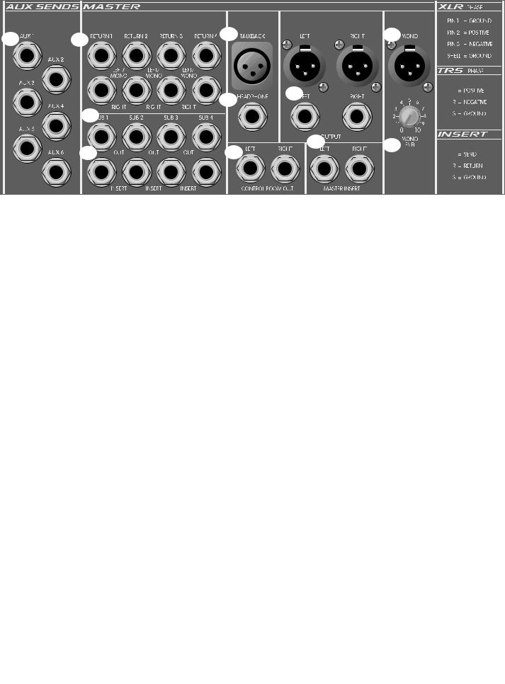
AUX Send
Output jack of the corresponding AUX mix. It is unbalanced, and can be used to feed an external monitor system or effect unit. The level is set by the AUX Master Level (#26) and the individual channel level control (see #10, 11).
tereo Return
High impedance input for line level signals. The left/mono input supplies signal to both the left and right inputs if there is no input connected to the right input jack.
Out
Output of the corresponding sub mix. It is unbalanced, with its output level set by the sub fader (#35).
Insert
1/4" stereo (TRS) jack which allows an external device to be inserted into the signal path before the
sub fader. The tip has the send signal, the ring is the return input. A switch in the jack normally connects the send to the return until a plug is inserted. The nominal level is -2 dBu.
Mic Input
Input connector for a low-impedance, balanced microphone used for house or stage communication. Pin 2 is the positive input. Phantom power is not available at this connector.
Output
This stereo jack (TRS) provides the signal to drive stereo headphones. It changes from the L-R mix to the PFL mix when the PFL is active. The level is set by the Headphone/Control Room Level Control (#48). Tip=Left, Ring=Right, Shield=Ground.
trol Room Output
1/4" left and right unbalanced outputs of the headphone mix to feed the control room monitor amps. The signal is exactly the same as that in the headphones.
Output
1/4" unbalanced and XLR balanced outputs of the Left and Right mixes. The level is set by the master left and right right faders (#36).
Main Insert
1/4" stereo (TRS) jack which allows an external device to be inserted into the signal path before the Master L/R Fader. The tip has the send signal, the ring is the return input. A switch in the jack normally
connects the send to the return until a plug is inserted. The nominal level is -2 dBu.
Mono Output
An XLR balanced output of the mono mix. The level is set by the Mono Level control (#59). Pin 2 is the positive output.
Mono Level
Adjusts the level of the Balanced Mono Output (#58). The signal is a post fader sum of the left and right output signals. The center position is the unity gain setting; 7 dB of gain boost is available.
Page 9
62 |
61 |
|
|
|
|
|
|
|
|||||||||||||||||||||
|
|
|
|
|
|
|
|||||||||||||||||||||||
|
|
|
|
|
|
|
|
||||||||||||||||||||||
|
|
|
|
|
|
|
|
|
|
|
|
|
|
|
|
|
|
|
|
|
|
|
|
|
|
|
|
|
|
|
|
|
|
|
|
|
|
|
|
|
|
|
|
|
|
|
|
|
|
|
|
|
|
|
|
|
|
|
|
|
|
|
|
|
|
|
|
|
|
|
|
|
|
|
|
|
|
|
|
|
|
|
|
|
|
|
|
|
|
|
|
|
|
|
|
|
|
|
|
|
|
|
|
|
|
|
|
|
|
|
|
|
|
|
|
|
|
|
|
|
|
|
|
|
|
|
|
|
|
|
|
|
|
|
|
|
|
|
|
|
|
|
|
|
|
|
|
|
|
|
|
|
|
|
|
|
|
|
|
|
|
|
|
|
|
|
|
|
|
|
|
|
|
|
|
|
|
|
|
|
|
|
|
|
|
|
|
|
|
|
|
|
|
|
|
|
|
|
|
|
|
|
|
|
|
|
|
|
|
|
|
|
|
|
|
|
|
|
|
|
|
|
|
|
|
|
|
|
|
|
|
|
|
|
|
|
|
|
|
|
|
|
|
|
|
|
|
|
|
|
|
|
|
|
|
|
|
|
|
|
|
|
|
|
|
|
|
|
|
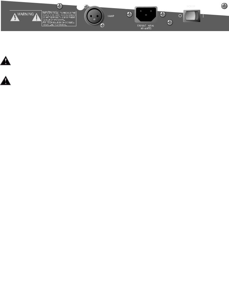
60. |
Power |
|
|
|
The mixer’s main power switch. The power on LED indicator will light when the unit is powered. |
|
|
61. |
AC Mains Input |
|
|
|
Connect the line cord to this connector to provide power to the unit. Damage to the equipment may result if |
|
|
|
improper line voltage is used. (See line voltage marking on unit.) |
|
|
|
Line Cord |
|
|
|
For your safety, we have incorporated a 3-wire line (mains) cable with proper grounding facilities. It is not |
|
|
|
advisable to remove the ground pin under any circumstances. If it is necessary to use the equipment without |
|
|
|
proper grounding facilities, suitable grounding adaptors should be used. Less noise and greatly reduced |
|
|
|
shock hazard exists when the unit is operated with the proper grounded receptacles. |
|
|
62. |
Lamp Connector |
|
|
|
Two XLR connectors are provided for low-voltage lamps (such as the Peavey ML |
™ -2 |
™ -3) to illuminate the |
|
console in poorly lit environments. Each connector supplies 12V AC at 200ma between pins 1 and 2. The total |
|
|
|
maximum load should not exceed 400ma. These connectors are short-circuit protected, with automatic reset |
|
|
|
when a short is removed. |
|
|
|
APPLICATIONS |
The SRC |
® series of mixers were primarily designed for sound reinforcement applications, but are very |
capable recording mixers as well. Here are some typical methods of hook-up:
SOUND REINFORCEMENT |
: |
|
|
|
|
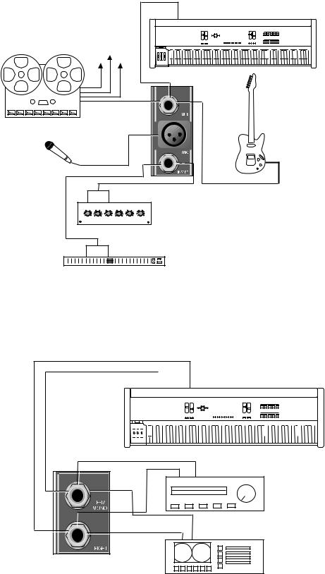
1.Microphones and other low impedance sources are connected to the XLR mic inputs; high level line inputs such as electronic musical instruments are connected to the line inputs. If problems arise because a microphone either picks up an out-of-phase signal (as when using multiple drum microphones), or a very loud signal causes clipping even at a minimum gain setting (as when close miking an amplifier or a drum head), it should
be connected to a channel with pad and polarity switches. Stereo line level sources (synth, tape, CD, etc.) should be connected to one of the stereo channels, or to two of the mono line inputs (one panned left, the other panned right), or to a Return input that is not used for effects.
2.The house power amplifier inputs should be connected to the main Left and Right outputs, or to the Mono output. The Mono output is a blend of the Left and Right output signals (post master fader) and has its own level control. It can be used to drive an additional amplifier that needs an independently set volume.
3.Connect the monitor power amplifier input to the AUX 1, 2, 3 or 4 output. Four monitors are supported, with two additional available, if AUX 5 and 6 are also used for monitors (Pre) and not for effect sends (Post).
4. If an effect device is used, connect its input to the AUX 5 or 6 output. These outputs can also be configured as a stereo pair (AUX 5 is the left, AUX 6 is the right) in the two stereo channels, and can be set up to feed a true stereo effects processor.
5.The effect device outputs are connected to the Return 1, 2, 3 or 4 inputs.
6.Connect a tape recorder to the Tape input and Tape output jacks. Care should be taken not to record on a deck that has its outputs connected to the tape input jacks and have the tape input level control turned up, or nasty
feedback will result. If four-band equalization or a more specialized monitor send is needed, a stereo line channel can be used for tape input (see #1 and #24). Alternatively, a stereo return can be used for tape input. Both Return 3 and 4 have two-band EQ as well as monitor sends (to AUX 1 and 2) and full bus assignment capability.
Page 10
APPLICATIONS (Cont.)
RECORDING:
The connections for recording are very similar to those of the sound reinforcement section above with the following differences:
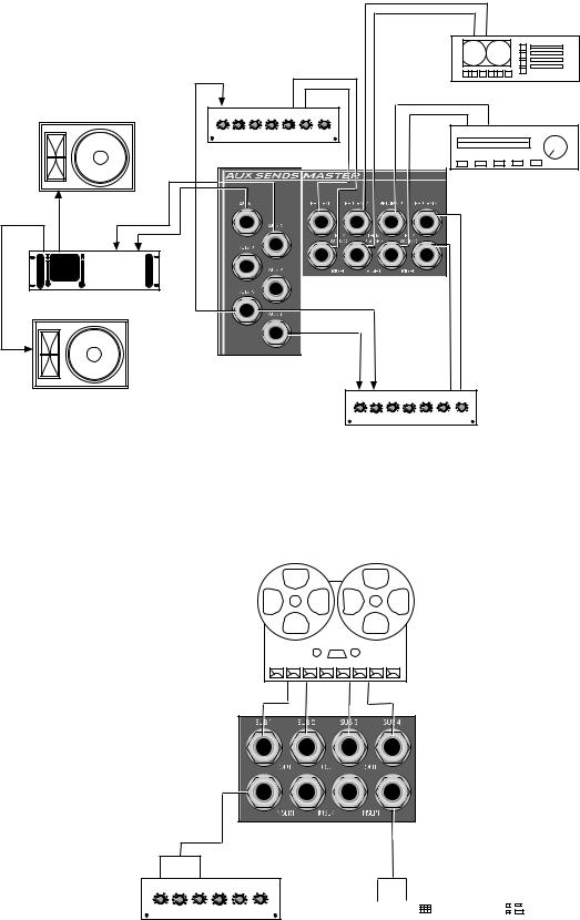
1. For recording tracks, connect the input sources as described above and use the sub mix sends to
feed the recorder's inputs. For mixdown, the multitrack recorder's outputs are connected to the line inputs and assigned to the L/R mix.
2.Connect the Sub outputs (the Left and Right outputs are included in this group if they are not in use) to the tape recorder inputs. The inserts can be used to patch compressors or EQ into the path. If effects are not being used, AUX 5 and 6 can also be used as sub mixes. If even more outputs are
needed, the individual channel's insert jack can be used for a direct output. It is pre-EQ, pre-fader.
3.Connect the Left and Right outputs to the two-track mixdown deck inputs. If a graphic EQ, compressor/limiter, or enhancer is used, connect it to the Left and Right Insert Jacks.
4.The control room monitor amplifiers are connected to the Control Room Outputs. This is the same
signal that is in the headphone output.
5.Effect device inputs are connected to AUX 5 or 6 outputs. If a stereo send is required, use AUX 5 for left and AUX 6 for right.
6.Effect device outputs are connected to Returns 1, 2, 3, 4 or any unused channel inputs (mono or
stereo). If a channel input is used, make sure that the AUX send being used to feed the effects device is not turned up for that channel or it will output into its own input and awesome feedback will occur.
HOUSE |
|
HOUSE MONO |
SPEAKERS |
|
|
|
SPEAKERS |
|
|
|
|
LEFT |
|
RIGHT |
OUT |
|
|
L |
R |
OUT |
|
||
L |
|
IN |
IN |
|
|
|
|
|
R |
|
|
POWER AMP (STEREO) |
POWER AMP (MONO) |
|
TALK BACK |
|
|
MIC |
|
|
|
|
|
|
|
|
|
|
IN |
|
STEREO |
|
|
|
|
|
|
|
|
HEADPHONES |
|
|
|
|
|
|
|
|
|
|
|
|
|
|
|
2 TRACK MIX DOWN DECK |
|
|
|
|
|
DIAGRAM |
|
|
|
|
|
|
|
|
SECTION OF |
|
|
|
|
|
|
|
|
SRC MIXER |
|
|
|
|
L |
|
|
|
|
|
|
|
LEFT |
L |
IN |
R |
|
OUT |
|
|
|
|
|
IN |
|
IN |
|
OUT |
||
|
|
|
|
|
||||
|
|
|
5 |
5 |
5 |
5 |
5 |
5 |
|
OUT |
|
|
|
|
|
|
|
CONTROL |
|
|
|
COMPRESSOR / LIMITER |
|
|
||
ROOM |
POWER AMP (STEREO) |
|
|
|
|
|
|
|
MONITORS |
|
|
|
|
|
|
|
|
|
|
|
IN |
|
OUT |
IN |
|
OUT |
|
R |
|
|
|
|
|
|
|
RIGHT |
|
|
EQUALIZER |
|
|
|
|
|
|
|
|
|
|
|
|
|
|
STUDIO/LIVE RECORDING CONFIGURATION
Page 11
MONITOR 1
SPEAKER
R |
|
|
L |
R |
L |
OUT |
|
IN |
STEREO POWER AMP |
|
|
SPEAKER |
|
|
MONITOR 2 |
|
|
|
|
|
|
|
|
|
|
|
L |
|
|
|
|
|
|
|
|
|
R |
|
|
|
|
|
|
|
|
|
OUT |
|
|
|
|
|
|
R |
|
|
|
|
|
|
|
|
|
L |
|
|
TAPE PLAYER |
|
|
|
|
|
|
|
|
|
|
|
MONO IN |
|
|
|
|
STEREO OUT |
|
|
L |
|
|
|
|
|
|
|
|
|
R |
5 |
5 |
5 |
5 |
5 |
5 |
5 |
|
|
OUT |
|
|
|
|
|
|
|
|
|
|
EFFECTS DEVICE |
|
|
|
|
|
|
|
|
|
|
|
|
|
|
|
|
|
|
CD PLAYER |
|
|
|
|
|
SECTIONED AREA OF |
|
|
|
|
|
|
|
|
|
SRC MIXER |
|
|
|
|
|
|
|
|
|
|
R |
L |
R |
L |
|
|
|
|
|
|
|
|
||
|
|
|
|
|
|
STEREO IN |
|
|
STEREO OUT |
5 |
5 |
5 |
5 |
5 |
5 |
5 |
EFFECTS DEVICE
AUX SEND/RETURN APPLICATION
MULTI TRACK
RECORDER
INPUTS |
IN |
|
|
OUT |
|
|
|
5 |
5 |
5 |
5 |
5 |
5 |
OUT |
|
|
|
|
|
IN |
|
|
|
|
|
|
|
|
|
|
|
|
|
|
|
|
|
|
|
|
|
|
|
|
|
|
|
|
|
|
|
|
|
|
|
|
|
|
|
|
|
|
|
|
|
|
|
|
|
|
|
|
|
|
|
|
|
|
|
|
|
|
|
|
|
|
|
|
|
|
|
|
|
|
|
|
|
|
|
|
|
|
|
|
|
|
|
|
|
|
|
|
|
|
|
|
|
|
COMPRESSOR /GATE |
|
|
|
|
|
|
|
|
|
|
|
|
|
|
|
|
|
|
|
|
|
EQUALIZER |
|
|
|
|||||||||||||||||||||||
|
|
|
|
|
|
|
|
|
|
|
|
|
|
|
|
|
|
|
|
|
|
|
|
|
|
|
|
|
|
|
|
|
|
|
|
|
|
|
|
|
|
|
|
|
|
|
|
|
MULTI TRACK/SUB APPLICATION
Page 12
TO OTHER
CHANNEL INPUTS
OUT
MULTI TRACK
RECORDER
MICROPHONE
IN |
|
|
OUT |
|
|
5 |
5 |
5 |
5 |
5 |
5 |
|
COMPRESSOR /GATE |
|
|
||
IN |
|
|
OUT |
|
|
|
EQUALIZER |
|
|
||
R
L
|
|
|
|
MONO OUT |
|
|
|
|
|
|
|
|
|
|
|
|
|
|
|
|
|
|
|
|
|
|
|
|
|
|
SYNTHESIZER |
|||||||||||||||||||
|
|
|
|
|
|
|
|
|
|
|
|
|
|
|
|
|
|
|
|
|
|
|
|
|
|
|
|
|
|
|
|
|
|
|
|
|
|
|
|
|
|
|
|
|
|
|
|
|
|
|
|
|
|
|
|
|
|
|
|
|
|
|
|
|
|
|
|
|
|
|
|
|
|
|
|
|
|
|
|
|
|
|
|
|
|
|
|
|
|
|
|
|
|
|
|
|
|
|
|
|
|
|
|
|
|
|
|
|
|
|
|
|
|
|
|
|
|
|
|
|
|
|
|
|
|
|
|
|
|
|
|
|
|
|
|
|
|
|
|
|
|
|
|
|
|
|
|
|
|
|
|
|
|
|
|
|
|
|
|
|
|
|
|
|
|
|
|
|
|
|
|
|
|
|
|
|
|
|
|
|
|
|
|
|
|
|
|
|
|
|
|
|
|
|
|
|
|
|
|
|
|
|
|
(ACTIVE
ELECTRONICS)
CHANNEL INPUT/EFFECTS APPLICATION
NOTE: Mic inputs and line inputs of the same channel cannot be used simultaneously. The diagram above shows various output devices
which can be connected.
STEREO OUT |
|
|
|
|
|
|
|
|
|
|
|
|
|
|
|
|
|
|
|
|
|
|
|
|
|
|
|
SYNTHESIZER |
|||||||||||||||||||||||||||||
|
|
|
|
|
|
|
|
|
|
|
|
|
|
|
|
|
|
|
|
|
|
|
|
|
|
|
|
|
|
|
|
|
|
|
|
|
|
|
|
|
|
|
|
|
|
|
|
|
|
|
|
|
|
|
|
|
|
|
|
|
|
|
|
|
|
|
|
|
|
|
|
|
|
|
|
|
|
|
|
|
|
|
|
|
|
|
|
|
|
|
|
|
|
|
|
|
|
|
|
|
|
|
|
|
|
|
|
|
|
|
|
|
|
|
|
|
|
|
|
|
|
|
|
|
|
|
|
|
|
|
|
|
|
|
|
|
|
|
|
|
|
|
|
|
|
|
|
|
|
|
|
|
|
|
|
|
|
|
|
|
|
|
|
|
|
|
|
|
|
|
|
|
|
|
|
|
|
|
|
|
|
|
|
|
|
|
|
|
|
|
|
|
|
|
|
|
|
|
|
|
|
|
|
|
|
|
|
|
|
|
|
|
|
|
|
|
|
|
|
|
|
|
|
|
|
|
|
|
|
|
|
|
|
|
|
|
|
|
|
|
|
|
|
|
|
|
|
|
|
|
|
|
|
|
|
|
|
|
|
|
|
|
|
|
|
|
|
|
|
|
|
|
|
|
|
|
|
|
|
|
|
|
|
|
|
|
|
|
|
|
|
|
|
|
|
|
|
|
|
|
|
|
|
|
|
|
|
|
|
|
|
|
|
|
|
|
|
|
|
|
|
|
|
|
|
|
|
|
|
|
|
|
|
|
|
|
|
|
|
|
|
|
|
|
|
|
|
STEREO |
CHANNEL |
L
R
OUT
L
CD PLAYER
R
OUT
TAPE PLAYER
STEREO
CHANNEL
STEREO CHANNEL INPUT APPLICATION
Page 13
SRC |
® 4018, 4026 and 4034 |
Sound Reinforcement Mixer Specifications:
Input Specifications:
Function |
Input Z |
Input |
|
Input Levels |
|
Balanced/ |
Connector |
|
(ohms) |
Gain |
|
|
|
Unbalanced |
|
|
Min |
Setting |
Min** |
Nominal* |
Max |
|
|
Microphone |
5K |
Max gain |
-72 dBu |
-52 dBu |
-34 dBu |
Balanced |
XLR Pin 1 Gnd, |
(150 ohms) |
|
(56 dB) |
|
|
|
|
Pin 2 (+), |
|
|
Min gain |
-26 dBu |
-6 dBu |
+10 dBu |
|
Pin 3 (-) |
|
|
(10 dB) |
|
|
|
|
|
|
|
|
|
|
|
|
|
Line |
10K |
Max gain |
-62 dBu |
-42 dBu |
-24 dBu |
Balanced |
1/4" TRS; Tip (+), |
(10K ohms) |
|
(46 dB) |
|
|
|
|
Ring (-), Sleeve |
|
|
Min gain |
-16 dBu |
+4 dBu |
+20 dBu |
|
Ground |
|
|
(0 dB) |
|
|
|
|
|
|
|
|
|
|
|
|
|
Insert |
22K |
N/A |
-16 dBu |
+4 dBu |
+20 dBu |
Unbalanced |
1/4" TRS; Tip Send, |
Return |
|
(0 dB) |
|
|
|
|
Ring Return, |
|
|
|
|
|
|
|
Sleeve Ground |
Stereo |
20K |
Max gain |
-36 dBu |
-16 dBu |
0 dBu |
Unbalanced |
1/4" Phono |
Line |
|
(20 dB) |
|
|
|
|
|
Input |
|
Min gain |
-16 dBu |
+4 dBu |
+20 dBu |
|
|
|
|
(0 dB) |
|
|
|
|
|
|
|
|
|
|
|
|
|
Aux |
22K |
N/A |
-12 dBu |
+4 dBu |
+20 dBu |
Unbalanced |
1/4" Phono |
Return |
|
(0 dB) |
|
|
|
|
|
|
|
|
|
|
|
|
|
Tape |
10K |
N/A |
-26 dBu |
-10 dBu |
+6 dBu |
Unbalanced |
RCA Jacks |
|
|
(14 dB) |
|
|
|
|
|
|
|
|
|
|
|
|
|
0 dBu = 0.775V (RMS) |
|
|
|
|
|
|
|
**Min input level (Sensitivity) is the smallest signal that will produce nominal output (+4 dBu) with sub and master controls set for maximum gain.
*Nominal settings are defined as all controls set at 0 dB (or 50% rotation for rotary pots) except the gain adjustment pot, which is as specified.
Page 14

Output Specifications:
|
Function |
|
Minimum |
OutputInput Levels |
|
Balanced/ |
Connector |
|||||
|
|
|
Load Z |
|
|
|
|
|
|
|
Unbalanced |
|
|
|
|
(ohms) |
Nominal* |
Max |
|
|
|
||||
|
Main L/R |
|
600 |
+4 dBu |
- |
|
|
dBu |
|
Both |
1/4" Phono (Unbal), |
|
|
|
+2034 |
|
|||||||||
|
|
|
|
|
|
|
|
|
|
|
|
XLR Pin 1 Gnd, |
|
|
|
|
|
|
|
|
|
|
|
|
|
|
|
|
|
|
|
+2610 |
dBu |
|
|
Pin 2 (+), |
||
|
|
|
|
|
|
|
|
|
|
|
|
Pin 3 (-) (Bal) |
|
|
|
|
|
|
|
|
|
|
|
|
|
|
|
|
|
|
|
|
|
|
|
|
|
|
|
Mono |
|
600 |
+4 dBu |
|
|
+20 dBu |
|
Balanced |
XLR Pin 1 Gnd, |
||
|
|
|
|
|
|
|
|
|
|
|
|
Pin 2 (+), |
|
|
|
|
|
|
|
|
|
|
|
|
Pin 3 (-) |
|
|
|
|
|
|
|
|
|
|
|
|
|
|
Sub Master |
|
600 |
+4 dBu |
+20 dBu |
|
Unbalanced |
1/4" Phono |
||||
|
|
|
|
|
|
|
|
|
|
|
|
|
|
Aux Send |
|
600 |
+4 dBu |
|
|
+20 dBu |
|
Unbalanced |
1/4" Phono |
||
|
|
|
|
|
|
|
|
|
|
|
|
|
|
Channel |
|
600 |
+4 dBu |
+20 dBu |
|
Unbalanced |
1/4" TRS: Tip Send, |
||||
|
Insert Send |
|
|
|
|
|
|
|
|
|
|
Ring Return, |
|
|
|
|
|
|
|
|
|
|
|
|
Sleeve Ground |
|
|
|
|
|
|
|
|
|
|
|
|
|
|
Sub |
|
600 |
+4 dBu |
|
|
+20 dBu |
|
Unbalanced |
1/4" TRS: Tip Send, |
||
|
Insert Send |
|
|
|
|
|
|
|
|
|
|
Ring Return, |
|
|
|
|
|
|
|
|
|
|
|
|
Sleeve Ground |
|
|
|
|
|
|
|
|
|
|
|
|
|
|
Control |
|
600 |
+4 dBu |
|
|
+20 dBu |
|
Unbalanced |
1/4" Phono |
||
|
Room |
|
|
|
|
|
|
|
|
|
|
|
|
|
|
|
|
|
|
|
|
|
|
|
|
|
Headphone |
|
8 |
+4 dBu |
|
|
+20 dBu |
|
Unbalanced |
1/4" TRS: Tip Left, |
||
|
|
|
|
(no load) |
|
|
|
|
|
|
|
Ring Right, |
|
|
|
|
|
|
|
|
|
|
|
|
Sleeve Ground |
|
|
|
|
|
|
|
|
|
|
|
|
|
|
Tape |
|
10K |
-2 dBu |
|
|
+20 dBu |
|
Unbalanced |
RCA Jack |
||
|
|
|
|
|
|
|
|
|
|
|
|
|
|
0 dBu = 0.775V (RMS) |
|
|
|
|
|
|
|
|
|
||
Gain: |
|
|
|
|
|
|
|
|
|
|
||
Mic Input Gain Adj Range: |
|
|
|
|
|
|
|
10 dB to 56 dB |
|
|||
Mic Input to Sub Output |
|
|
|
|
|
|
|
76 dB (Max Gain) |
|
|||
Mic Input to longest path |
|
|
|
|
|
|
|
93 dB (Max Gain) |
|
|||
Line Input Gain Adj Range: |
|
|
|
|
|
|
|
0 dB to 46 dB |
|
|||
Line Input to Sub Output |
|
|
|
|
|
|
|
66 dB (Max Gain) |
|
|||
Line Input to longest path |
|
|
|
|
|
|
|
83 dB (Max Gain) |
|
|||
Stereo Line Input Gain Adj Range |
|
|
|
|
|
|
0 dB to 20 dB |
|
||||
Stereo Line Input to Sub Output |
|
|
|
|
|
|
40 dB (Max Gain) |
|
||||
AUX Stereo Line Input longest path |
|
|
|
|
|
|
57 dB (Max Gain) |
|
||||
AUX Return to Sub Output |
|
|
|
|
|
|
16 dB (Max Gain) |
|
||||
AUX Return longest path |
|
|
|
|
|
|
33 dB (Max Gain) |
|
||||
Frequency Response:
Mic Input to L-R Output 20 Hz to 30kHz +0 dB / -1 dB Stereo Input to L-R Output 20 Hz to 30k Hz +0 dB / -1 dB
Total Harmonic Distortion (THD):
<0.007% 20 Hz to 20 k Hz Mic to L-R output at Nominal Level (20 Hz to 80 kHz BW)
Page 15
 Loading...