


Q™231 F X
Dual 31Band Graphic Equalizer with FLS ®
Constant Q Filters
O W N E R ’ S M A N U A L

Intended to alert the user to the presence of uninsulated "dangerous voltage" within the product's enclosure that may be of sufficient magnitude to constitute a risk of electric shock to persons.
Intended to alert the user of the presence of important operating and maintenance (servicing) instructions in the literature accompanying the product.
CAUTION: Risk of electrical shock – DO NOT OPEN!
CAUTION: To reduce the risk of electric shock, do not remove cover. No user serviceable parts inside. Refer servicing to qualified service personnel.
WARNING: To prevent electrical shock or fire hazard, do not expose this appliance to rain or moisture. Before using this appliance, read the operating guide for further warnings.
Este símbolo tiene el propósito de alertar al usuario de la presencia de "(voltaje) peligroso" que no tiene aislamiento dentro de la caja del producto que puede tener una magnitud suficiente como para constituir riesgo de corrientazo.
Este símbolo tiene el propósito de alertar al usario de la presencia de instruccones importantes sobre la operación y mantenimiento en la literatura que viene con el producto.
PRECAUCION: Riesgo de corrientazo – No abra.
PRECAUCION: Para disminuír el riesgo de corrientazo, no abra la cubierta. No hay piezas adentro que el usario pueda reparar. Deje todo mantenimiento a los técnicos calificados.
ADVERTENCIA: Para evitar corrientazos o peligro de incendio, no deje expuesto a la lluvia o humedad este aparato Antes de usar este aparato, lea más advertencias en la guía de operación.
Ce symbole est utilisé pur indiquer à l'utilisateur la présence à l'intérieur de ce produit de tension non-isolée dangereuse pouvant être d'intensité suffisante pour constituer un risque de choc électrique.
Ce symbole est utilisé pour indiquer à l'utilisateur qu'il ou qu'elle trouvera d'importantes instructions sur l'utilisation et l'entretien (service) de l'appareil dans la littérature accompagnant le produit.
ATTENTION: Risques de choc électrique – NE PAS OUVRIR!
ATTENTION: Afin de réduire le risque de choc électrique, ne pas enlever le couvercle. Il ne se trouve à l'intérieur aucune pièce pouvant être réparée par l'utilisateur. Confier l'entretien à un personnel qualifié.
AVERTISSEMENT: Afin de prévenir les risques de décharge électrique ou de feu, n'exposez pas cet appareil à la pluie ou à l'humidité. Avant d'utiliser cet appareil, lisez les avertissements supplémentaires situés dans le guide.
Dieses Symbol soll den Anwender vor unisolierten gefährlichen Spannungen innerhalb des Gehäuses warnen, die von Ausreichender Stärke sind, um einen elektrischen Schlag verursachen zu können.
Dieses Symbol soll den Benutzer auf wichtige Instruktionen in der Bedienungsanleitung aufmerksam machen, die Handhabung und Wartung des Produkts betreffen.
VORSICHT: Risiko – Elektrischer Schlag! Nicht öffnen!
VORSICHT: Um das Risiko eines elektrischen Schlages zu vermeiden, nicht die Abdeckung enfernen. Es befinden sich keine Teile darin, die vom Anwender repariert werden könnten. Reparaturen nur von qualifiziertem Fachpersonal durchführen lassen.
ACHTUNG: Um einen elektrischen Schlag oder Feuergefahr zu vermeiden, sollte dieses Gerät nicht dem Regen oder Feuchtigkeit ausgesetzt werden. Vor Inbetriebnahme unbedingt die Bedienungsanleitung lesen.
2
E N G L I S H
|
1 |
2 |
|
1 |
|
3 |
4 |
|
6 |
7 |
8 |
5 |
9 |
Congratulations on purchasing the Q™231FX! Peavey engineers have taken graphic equalizers to the next level with its introduction. The Q™231FX is designed to provide refined control over any sound reinforcement or studio application. We trust that you are eager to place this unit into YOUR system ASAP.
The Q231FX offers dual 31-band graphic equalization with 1/3 octave filters featuring superior constant “Q” devices. Each channel has balanced inputs/outputs and Peavey’s exclusive FLS™ Feedback Locating System that consists of LED indicators located above the frequency bands to identify the presence of a high energy signal (usually feedback). This sophisticated feedback detector system will allow you to quickly identify and remove feedback. It works like this: when the feedback detection circuit detects the frequency band with the most energy, it causes the LED above the associated frequency band to illuminate. By moving the fader downward for that band, the likelihood of feedback is reduced/eliminated.
Most people use the Q231FX in two ways:
1.To catch and reduce/eliminate feedback “on-the-fly” during a performance, and
2.To determine frequency bands that are susceptible to feedback BEFORE the performance, eliminating them in advance. How do you do this? After the system is set up, slowly bring up the microphone levels. As they start to feedback, note the LED activity on the Q231FX feedback bands. Move the faders to decrease the “identified” bands. Now you have eliminated a high percentage of potential feedback problems before the performance even begins!
NOTE: It is common for feedback to be active over several frequency bands. Also, go easy when making fader adjustments since extreme movements will affect your performance and be counter productive. If any operational questions come up, be sure and contact our Customer Service department at (601) 483-5365.
Thanks for supporting Peavey!
OPERATION NOTE
For best results, set the mixer levels high enough to cause the Feedback Locating System LEDs to become active (0 dBV, 1 V RMS). This may require you to turn down the power amp to maintain an acceptable volume level.
3
This equalizer is designed to provide room equalization, feedback control, and system tone control. No amount of equalization will correct an acoustically bad room/mic/speaker arrangement or completely correct the response curve of a poor loudspeaker.
Always begin with all sliders in the “0” position and avoid excessively cutting large segments of the audio passband, as this will limit the system's dynamic range.
Exercise caution when attempting to boost equalization below cutoff of the speaker system. Typical sound reinforcement enclosures are not designed for 20 Hz performance and transducer damage could result.
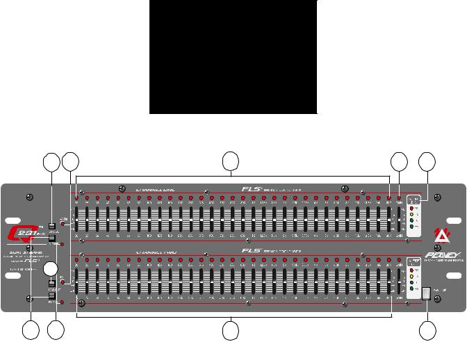
LOW CUT (1)
Provides high pass filtering at 40 Hz in the “in” position. Low frequency roll-off is at 12 dB per octave. There is one on each channel.
LOW CUT LED (2)
With the low cut switch in the “in” position, this LED will illuminate indicating a low frequency roll-off at 12 dB per octave at 40 Hz. There is one on each channel.
BYPASS (3)
In bypass mode (switch in), the input signal is routed directly to the output and is unaffected by all front panel controls with the exception of the low cut filter. There is one on each channel.
BYPASS LED (4)
This LED will illuminate when the bypass switch is in the “in” position indicating that the EQ and gain controls are bypassed. There is one on each channel.
EQUALIZER SECTION (5)
31-bands of 1/3 octave filters. The filters are constant “Q” devices located at ISO center frequencies. Effective equalization range is from 20 Hz to 20 kHz. Maximum boost per frequency is 12 dB and the maximum cut per frequency is 18 dB.
AUTOMATIC FEEDBACK LOCATING LEDS (6)
When feedback occurs, the LED of the frequency band that is feeding back will illuminate over the slider that needs adjusting. The LED will remain illuminated for a few seconds even after the feedback is gone. This allows you to see where the feedback is if the feedback goes away before any correction is made. If there is no feedback occurring, all the LEDs will become active acting as a basic real-time analyzer.
OPERATING THE FEEDBACK LOCATING SYSTEM
The feedback locating system is normally used in one of two ways.
1.To catch and reduce/eliminate feedback “on-the-fly” during a performance.
2.To determine frequency bands that are susceptible to feedback before the performance, and eliminate them in advance. This is done, after the system is set up, by bringing up the microphone levels slowly to the point of feedback. As they start to feedback, note the LED activity on the Q231 FX. Move the faders to decrease the “identified” bands. Now you have eliminated a high percentage of potential feedback problems before the performance even begins.
Note: It is not uncommon for feedback to occur over several frequency bands. Also, go easy when making fader adjustments since extreme movements will affect your performance and be counter productive. Some feedback or ringing, although audible, may not be louder than the other program material and may not light an LED.
GAIN (7)
Calibrated control for regulating overall gain of the equalizer section. Unity gain throughout the signal chain may be maintained by recovering lost signal at this point.
For example: Assume the equalization process has introduced a signal loss of -6 dB by negative ( - ) adjustment of the EQ section. The gain should then be adjusted to +6 dB to maintain unity gain through the equalizer.
4
LED LEVEL METER (8)
This multicolored LED ladder indicates output level. There is one on each channel.
POWER SWITCH (9)
Used to turn AC mains power on or off.
Back Panel:
10 |
11 |
12 |
13 |
14
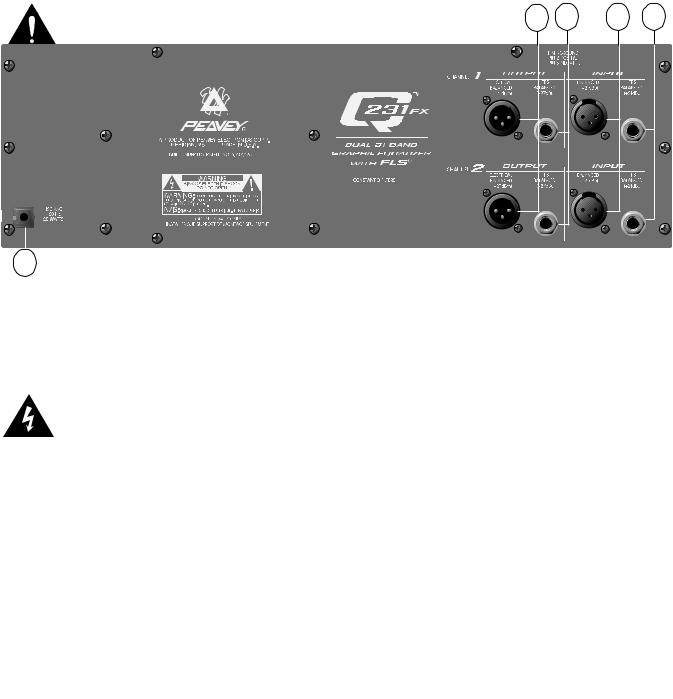
BACK PANEL FEATURES:
LINE CORD-120V PRODUCTS ONLY (10)
We have incorporated a 2-wire line (mains) cable for power on the Q231 FX.
Power requirements:
Domestic: 120 V AC / 60 Hz / 20 W.
Export: 230 V AC / 50/60 Hz / 20 W.
NOTE: CAUTION: TO PREVENT ELECTRIC SHOCK, MATCH WIDE BLADE OF PLUG TO WIDE SLOT, FULLY INSERT.
NOTE: FOR UK ONLY
As the colors of the wires in the mains lead of this apparatus may not correspond with the colored markings identifying the terminals in your plug, proceed as follows: (1) The wire which is colored green and yellow must be connected to the terminal which is marked by the letter E or by the earth symbol or colored green or green and yellow. (2) The wire which is colored blue must be connected to the terminal which is marked with the letter N or the color black. (3) The wire which is colored brown must be connected to the terminal which is marked with the letter L or color red.
XLR OUTPUTS (11)
This XLR jack provides an electronically balanced output that is electrically the same as the 1/4" TRS Output (11). Using this balanced output will provide a 6 dB increase from unbalanced operation.
1/4" OUTPUTS (12)
Two 1/4" Tip-Ring-Sleeve (stereo) jacks (one per channel) provide balanced outputs when used with stereo (TRS) 1/4" plugs and 2-conductor shielded cables. When used with a mono 1/4" phone plug, the outputs are unbalanced. The Tip is in phase ( + ) and the Ring is out of phase ( - ). Using this as a balanced output will provide a 6 dB increase from unbalanced operation.
XLR INPUTS (13)
This XLR jack provides a balanced input that is electrically the same as the 1/4" TRS Input (13).
1/4" INPUTS (14)
Two 1/4" Tip-Ring-Sleeve (stereo) jacks (one per channel) provide balanced inputs when used with stereo (TRS) 1/4" plugs and 2-conductor shielded cables. When used with a mono 1/4" phone plug, the inputs are unbalanced. The Tip is in phase ( + ) and the Ring is out of phase ( - ).
5

Q231 FX SPECIFICATIONS
All specifications are typical unless otherwise noted.
0 dBV = 1 volt
All specifications are referenced to nominal output level (0 dBV) unless otherwise stated. All measurements are wide band 20 Hz to 20 kHz unless otherwise stated.
All specifications measured at 1 V RMS input and unbalanced output. All sliders at mid position; all switches out unless otherwise noted.
Frequency Response:
±1 dB, 20 Hz to 20 kHz
Distortion:
0.005%, 20 Hz to 20 kHz
Output Headroom:
21 dB
Output Noise:
EQ in bypass: -101 dBV
EQ in filter: -95 dBV
Filter Frequencies:
20 Hz, 25 Hz, 32 Hz, 40 Hz, 50 Hz, 63 Hz, 80 Hz, 100 Hz, 125 Hz, 160 Hz, 200 Hz, 250 Hz, 315 Hz, 400 Hz, 500 Hz, 630 Hz, 800 Hz, 1 kHz, 1.25 kHz, 1.6 kHz, 2 kHz, 2.5 kHz, 3.15 kHz, 4 kHz, 5 kHz,
6.3 kHz, 8 kHz, 10 kHz, 12.5 kHz, 16 kHz, and 20 kHz
Filter Q:
Input Impedance:
Balanced 20K ohms (equal impedances to ground)
Output Impedance:
330 ohms
Maximum Input Level:
+21 dBV (8 V RMS)
Maximum Output Level:
+21 dBV (8 V RMS)
4.77
Maximum Boost and Cut Filter:
+12 dB, -18 dB
Maximum Boost and Cut Gain:
±15 dB
Low Cut Filter:
40 Hz
Power Consumption:
Nominal Input Level:
0 dBV (1 V RMS)
Nominal Output Level:
0 dBV (1 V RMS)
Input Headroom:
Nominal 21 dB
Domestic: 120 V AC, 60 Hz, 20 watts
Export: 220-230/240 V AC, 50/60 Hz, 20 watts
Dimensions and Weight:
5.25" H x 19" W x 10.75" D 11.7 lbs.
U.S. Patent Pending for circuit providing visual indication of feedback.
TM®
Due to our efforts for constant improvements,
features and specifications listed herein are subject to change without notice.
6
 Loading...