


P V ® S E R I E S A M P S
S T E R E O P O W E R A M P L I F I E R S
O P E R A T I N G G U I D E
Intended to alert the user to the presence of uninsulated “dangerous voltage” within the product’s enclosure that may be of sufficient magnitude to constitute a risk of electric shock to persons.
Intended to alert the user of the presence of important operating and maintenance (servicing) instructions in the literature accompanying the product.
CAUTION: Risk of electrical shock — DO NOT OPEN!
CAUTION: To reduce the risk of electric shock, do not remove cover. No user serviceable parts inside. Refer servicing to qualified service personnel.
WARNING: To prevent electrical shock or fire hazard, this apparatus should not be exposed to rain or moisture‚ and objects filled with liquids‚ such as vases‚ should not be placed on this apparatus. Before using this apparatus‚ read the operating guide for further warnings.
Este símbolo tiene el propósito, de alertar al usuario de la presencia de “(voltaje) peligroso” sin aislamiento dentro de la caja del producto y que puede tener una magnitud suficiente como para constituir riesgo de descarga eléctrica.
Este símbolo tiene el propósito de alertar al usario de la presencia de instruccones importantes sobre la operación y mantenimiento en la información que viene con el producto.
PRECAUCION: Riesgo de descarga eléctrica ¡NO ABRIR!
PRECAUCION: Para disminuír el riesgo de descarga eléctrica, no abra la cubierta. No hay piezas útiles dentro. Deje todo mantenimiento en manos del personal técnico cualificado.
ADVERTENCIA: Para prevenir choque electrico o riesgo de incendios, este aparato no se debe exponer a la lluvia o a la humedad. Los objetos llenos de liquidos, como los floreros, no se deben colocar encima de este aparato. Antes de usar este aparato, lea la guia de funcionamiento para otras advertencias.
Ce symbole est utilisé dans ce manuel pour indiquer à l’utilisateur la présence d’une tension dangereuse pouvant être d’amplitude suffisante pour constituer un risque de choc électrique.
Ce symbole est utilisé dans ce manuel pour indiquer à l’utilisateur qu’il ou qu’elle trouvera d’importantes instructions concernant l’utilisation et l’entretien de l’appareil dans le paragraphe signalé.
ATTENTION: Risques de choc électrique — NE PAS OUVRIR!
ATTENTION: Afin de réduire le risque de choc électrique, ne pas enlever le couvercle. Il ne se trouve à l’intérieur aucune pièce pouvant être reparée par l’utilisateur. Confiez I’entretien et la réparation de l’appareil à un réparateur Peavey agréé.
AVIS: Dans le but de reduire les risques d'incendie ou de decharge electrique, cet appareil ne doit pas etre expose a la pluie ou a l'humidite et aucun objet rempli de liquide, tel qu'un vase, ne doit etre pose sur celui-ci. Avant d'utiliser de cet appareil, lisez attentivement le guide fonctionnant pour avertissements supplémentaires.
Dieses Symbol soll den Anwender vor unisolierten gefährlichen Spannungen innerhalb des Gehäuses warnen, die von Ausreichender Stärke sind, um einen elektrischen Schlag verursachen zu können.
Dieses Symbol soll den Benutzer auf wichtige Instruktionen in der Bedienungsanleitung aufmerksam machen, die Handhabung und Wartung des Produkts betreffen.
VORSICHT: Risiko — Elektrischer Schlag! Nicht öffnen!
VORSICHT: Um das Risiko eines elektrischen Schlages zu vermeiden, nicht die Abdeckung enfernen. Es befinden sich keine Teile darin, die vom Anwender repariert werden könnten. Reparaturen nur von qualifiziertem Fachpersonal durchführen lassen.
WARNUNG: Um elektrischen Schlag oder Brandgefahr zu verhindern, sollte dieser Apparat nicht Regen oder Feuchtigkeit ausgesetzt werden und Gegenstände mit Flüssigkeiten gefuellt, wie Vasen, nicht auf diesen Apparat gesetzt werden. Bevor dieser Apparat verwendet wird, lesen Sie bitte den Funktionsführer für weitere Warnungen.
2

IMPORTANT SAFETY INSTRUCTIONS
WARNING: When using electrical products, basic cautions should always be followed, including the following:
1.Read these instructions.
2.Keep these instructions.
3.Heed all warnings.
4.Follow all instructions.
5.Do not use this apparatus near water.
6.Clean only with a dry cloth.
7.Do not block any of the ventilation openings. Install in accordance with manufacturer’s instructions.
8.Do not install near any heat sources such as radiators, heat registers, stoves or other apparatus (including amplifiers) that produce heat.
9.Do not defeat the safety purpose of the polarized or grounding-type plug. A polarized plug has two blades with one wider than the other. A grounding type plug has two blades and a third grounding plug. The wide blade or third prong is provided for your safety. If the provided plug does not fit into your outlet, consult an electrician for replacement of the obsolete outlet.
 . Protect the power cord from being walked on or pinched, particularly at plugs, convenience receptacles, and the point they exit from the apparatus.
11.Only use attachments/accessories provided by the manufacturer.
12.Use only with a cart, stand, tripod, bracket, or table specified by the manufacturer, or sold with the apparatus. When a cart is used, use caution when moving the cart/apparatus combination to avoid injury from tip-over.
13.Unplug this apparatus during lightning storms or when unused for long periods of time.
14.Refer all servicing to qualified service personnel. Servicing is required when the apparatus has been damaged in any way, such as power-supply cord or plug is damaged, liquid has been spilled or objects have fallen into the apparatus, the apparatus has been exposed to rain or moisture, does not operate normally, or has been dropped.
15.Never break off the ground pin. Write for our free booklet “Shock Hazard and Grounding.” Connect only to a power supply of the type marked on the unit adjacent to the power supply cord.
16.If this product is to be mounted in an equipment rack, rear support should be provided.
17.Exposure to extremely high noise levels may cause a permanent hearing loss. Individuals vary considerably in susceptibility to noise-induced hearing loss, but nearly everyone will lose some hearing if exposed to sufficiently intense noise for a sufficient time. The U.S. Government’s Occupational and Health Administration (OSHA) has specified the following permissible noise level exposures:
Sound Level dBA, Slow Response |
Duration Per Day In Hours |
8 |
90 |
6 |
92 |
4 |
95 |
3 |
97 |
3
PV® SERIES STEREO POWER AMPLIFIER
INTRODUCTION
Congratulations! You have just purchased a Peavey Electronics PV Series power amplifier. Using proven technology gained through years of amplifier design, this unit takes advantage of rugged TO-3P output devices mounted on massive aluminum extrusions and dissipates heat via an extremely quiet and effective 2- speed fan. PV amplifiers employ mammoth toroidal power transformers and offer impressive specifications and features not found on similarly priced competitive units. PV amplifiers are ruggedly constructed, rackmountable pieces of gear with superb patching capability, allowing superior flexibility in application. Front panel features include calibrated, detented gain (dB) controls and LED indicators for power (PWR), signal presence (SIG), and DDT™ (Distortion Detection Technique) activation on each channel, as well as a rocker mains POWER switch. The back panel contains an IEC connector for the mains power cord, a mains circuit breaker with reset, and the critical cooling fan opening. This opening should have an adequate supply of cool air and should never be blocked or restricted. Also on the back panel are the input and output sections, including an input barrier strip for permanent installations. Each channel input section includes a combo XLR / 1/4" phone jack connector and a THRU out. Channel output sections feature dual shock-proof binding posts and four-conductor Speakon® connectors. An additional 4-conductor Speakon connector allows BRIDGE mode output.
UNPACKING
Inspect the amplifier during unpacking. If any damage is found, notify your dealer immediately. Be sure to save the carton and all packing materials. Should you ever need to ship the unit back to Peavey Electronics, one of its service centers, or the dealer; use only the original factory packing.
INSTALLATION
PV series power amplifiers are designed for durability in live audio applications and commercial installations and also provide the quality performance required in studio and home applications. They are two-rack-space units of 16" (406 mm) depth designed to mount in a standard 19" rack. Rear mounting ears are provided for additional support. The minimum rack depth required from the mounting surface is 17" (432 mm) to allow adequate connector clearance.
BASIC SETUP
Rack mount the amplifier in the location where it is to be used, remembering to allow for adequate access and cooling space. Make all the connections to the proper INPUT connectors on the desired channel. Select the proper mode configuration (STEREO or BRIDGE). Connect speakers to the proper OUTPUT connectors, reviewing carefully the impedance and phase considerations. With the POWER switch OFF, connect the IEC cord (7) to the amplifier and then to a suitable electrical outlet to allow proper current draw. With both channel gain (dB) controls at their fully counterclockwise (-∞) settings, turn the POWER switch to ON, and slowly raise the gain controls to desired settings. Please carefully review this manual. It covers all this information in greater detail.
4

1 |
2 3 4 |
4 3 2 |
1 |
5 |
FRONT PANEL FEATURES
(1)INPUT GAIN (dB)
These controls are used to adjust the input gain of each channel. They determine how “loud” each channel of the power amplifier will sound for a given input signal level. Maximum input gain is achieved at the fully clockwise setting (+32 dB, 40 X), and this setting yields maximum mixer/system headroom. A setting of less than fully clockwise will yield lower system noise at the expense of mixer/system headroom. Turning the control fully counterclockwise is the “off” setting (-∞). It is always a good idea to power up any new installation at this setting to protect the system loudspeakers.
(2)POWER LEDS (PWR)
These indicators illuminate when the AC mains power is being supplied to the amp and both channels are operational. If either channel experiences fault conditions, exceeds safe operating temperature limits, or if the mains circuit breaker trips; both channel power LEDs will be dark, indicating “shutdown”. If the BRIDGE mode is selected, the PWR indicator on channel B will remain dark as a positive indication of this mode selection.
(3)SIGNAL ACTIVITY LEDS (SIG)
These indicators illuminate when the associated channel output signal level exceeds 1 V RMS.
(4)DDT™ ACTIVE LEDS
These indicators illuminate when DDT compression is taking place in the associated channel. With the DDT ENABLE / DEFEAT switch on the back panel in the DEFEAT position, these LEDs indicate clipping is occurring in the corresponding channel. The Peavey DDT compression system will be covered in greater detail later in this manual.
(5)POWER SWITCH
This heavy-duty, rocker-type switch turns on the mains power to the amplifier. When the mains power is applied, there is a 3-second delay in activation of the unit. This reduces/eliminates the turn-on transients associated with the system equipment connected to the amplifier and protects loudspeakers.
5
6 |
9 |
|
10 |
|
|
|
14 |
|||||||||
|
|
|
|
|
|
|
|
|
|
|
|
|
|
|
|
|
|
|
|
|
|
|
|
|
|
|
|
|
|
|
|
|
|
|
|
|
|
|
|
|
|
|
|
|
|
|
|
|
|
|
|
|
|
|
|
|
|
|
|
|
|
|
|
|
|
|
|
|
|
|
|
|
|
|
|
|
|
|
|
|
|
|
|
|
|
|
|
|
|
|
|
|
|
|
|
|
|
|
|
|
|
|
|
|
|
|
|
|
|
|
|
|
|
|
|
|
|
|
|
|
|
|
|
|
|
|
|
|
|
|
|
|
|
|
|
|
|
|
|
|
|
|
|
|
|
|
|
|
|
|
|
|
|
|
|
|
|
|
|
|
|
|
|
|
|
|
|
|
|
|
|
|
|
|
|
|
|
|
|
|
|
|
|
|
|
|
7 |
8 |
11 |
12 |
15 |
13 |
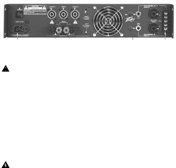
BACK PANEL FEATURES
(6)CIRCUIT BREAKER
There is one circuit BREAKER on the PV® amplifier. This breaker is provided to limit current to the associated power transformer, and protect it from overheating and possible destruction due to fault conditions in the unit. The trip current values have been carefully chosen to allow reasonable continuous power output performance, while still protecting the power transformer. This breaker should not trip unless there is a fault in the amplifier circuitry that causes excessive mains current draw. However, abnormal conditions such as a short circuit on either or both channels, or continuous operation at overload or clipping (especially into 2-ohm loads per channel or 4-ohm bridge load) can cause the breaker to trip. If this occurs, turn the POWER switch OFF and reset the breaker, after waiting a brief period of time to allow the unit to cool down. Efforts should be made to correct the cause of the overload if possible. When tripped, the button on the BREAKER will be outward approximately 1/4" and can be reset by pushing inward and upward. A normal reset button is relatively flat. If the breaker trips instantly each time you attempt to turn the unit on, it should be taken to a qualified Peavey Service Center for repair.
(7)IEC MAINS CONNECTOR
This is a standard IEC power connector. An AC mains cord having the appropriate AC plug and ratings for the intended operating voltage is included in the carton.
U.S. DOMESTIC AC MAINS CORD
The mains cord supplied with the unit is a heavy-duty, 3-conductor type with a conventional 120 VAC plug with ground pin. It should be connected to an independent circuit capable of continuously supporting at least 15 amps. This is particularly critical for sustained high-power applications. If the outlet used does not have a ground pin, a suitable grounding adapter should be used and the third wire grounded properly.
Never break off the ground pin on any equipment. It is provided for your safety.
The use of extension cords should be avoided but, if necessary, always use a 3-wire type with at least a #14 AWG wire size. The use of lighter wire will severely limit the power capability of this amplifier. Always use a qualified electrician to install any new electrical equipment. To prevent the risk of shock or fire hazard, always be sure that the amplifier and all associated equipment is properly grounded.
NOTE: FOR UK ONLY
If the colors of the wires in the mains lead of this unit do not correspond with the colored markings identifying the terminals in your plug, proceed as follows: (1) The wire that is colored green and yellow must be connected to the terminal that is marked by the letter E, the earth symbol, colored green, or colored green and yellow. (2) The wire that is colored blue must be connected to the terminal that is marked with the letter N or the color black. (3) The wire that is colored brown must be connected to the terminal that is marked with the letter L or the color red.
(8)BINDING POST OUTPUTS
Shockproof binding post speaker outputs are provided on the PV® amplifier. For each channel, the
6

outputs are in parallel and the speaker connection cables can be terminated with banana plugs or stripped wires for use in the binding post terminals, or can be connected using the Speakon® outputs
(9). For sustained high-power applications, either outputs can be used; however, exercise care to assure the correct speaker phasing. The red binding posts are the signal outputs from each channel, and the black binding posts are chassis ground. The red binding post should be connected to the positive inputs of the associated loudspeakers. For BRIDGE mode operation, only the red binding posts are used and the associated loudspeaker load is connected between the two red posts.
WARNING…Regardless of what connections are used, the minimum parallel speaker load should always be limited to 4 ohms per channel or 8 ohms BRIDGE mode for any application. Operation at loads of 4 ohms per channel, or 8 ohms BRIDGE mode, is more desirable for sustained operation applications because the amplifier will run much cooler at this loading. Operation above 4 ohms per channel and even open-circuit conditions can always be considered safe, but sustained operation at loads below 4 ohms could result in temporary amplifier shut down due to the thermal limit circuitry.
(9)SPEAKON® OUTPUTS
PV® amplifiers utilize three 4-conductor Speakon connectors, one for each channel and one for BRIDGE mode. Please refer to the BRIDGE MODE section of this manual before attempting to use this mode. For each channel Speakon, the same impedance rules apply as with the binding posts. Internally, all the Speakons are wired in what is called the “high current” mode, with pins 1+ and 2+ in parallel, and pins 1- and 2- in parallel. For the CHANNEL A and CHANNEL B Speakons, the respective channel output appears on pins 1+ and 2+. Pins 1- and 2- are chassis ground. For the BRIDGE Speakon, CHANNEL A appears on pins 1+ and 2+, and CHANNEL B appears on pins 1- and 2-. Always check the Speakon connector wiring carefully before using.
(10)MODE SWITCH
This switch is used to select STEREO or BRIDGE mode operation. It is a conventional push-push
type, requiring a small “tool” to activate. The IN position is BRIDGE mode; the OUT position is STEREO mode. Exercise care when selecting the BRIDGE mode. Accidental selection of this mode could damage loudspeakers, particularly in bi-amped systems. Amplifier BRIDGE mode theory will be covered later in this manual.
(11)DDT™ (DISTORTION DETECTION TECHNIQUE) SWITCH
This switch is used to enable or defeat the DDT compressor circuitry. It is also a conventional pushpush type, requiring a small “tool” to activate. The IN position is DEFEAT; the OUT position is ENABLE. Normally, the DDT function should be enabled to minimize the possibility of either or both channels going into clipping or overload. With this feature defeated, a severe overload could cause the mains circuit breaker to trip. The Peavey DDT compression system will be covered in greater detail later in this manual.
(12)FAN GRILL
A 2-speed DC fan supplies cool air to the amplifier. THIS INTAKE SHOULD NEVER BE BLOCKED! The fan switches to high speed automatically when the unit requires additional cooling. At idle and cool, the fan should be in low speed. The fan should never stop unless the amplifier is switched OFF or the AC mains power source is interrupted.
(13)INPUT BARRIER STRIP
A barrier strip is provided for input connections using bare wire or spade lug connections. PV amplifiers employ low-noise, electronically balanced input circuitry. This circuitry offers a very wide dynamic range capable of handling virtually any input signal level, while providing excellent common mode rejection to minimize hum and reduce interference. This strip accepts balanced and unbalanced audio signals. The "+" and "-" terminals are the positive and negative inputs to the respective channels. The GND terminal is the common ground to both channel inputs. For use with an unbalanced source, connect the "-" input terminal of the channel to ground with a jumper. If the "-" input is left floating, a 6 dB loss in channel gain will result and the floating input terminal may pick up outside noise.
7
(14)COMBO INPUT CONNECTOR
The combo connector offers both female XLR and 1/4" phone jack balanced inputs for each channel. The XLR is wired with pin 1 as ground, pin 2 positive input, and pin 3 negative input. The 1/4" phone jack is a tip/ring/sleeve (3-conductor) type, with the tip being positive input, the ring negative input, and the sleeve ground. It is important to realize that the XLR, 1/4" jack, and barrier strip inputs are all in parallel; therefore a balanced input to the associated channel can be accomplished using a male XLR, a 3-conductor phone jack, or bare wires connected to the barrier strip.
As an alternative, the 1/4" input can also be used with a regular tip/sleeve (2-conductor) type plug commonly found on single-conductor shielded patch cords. In this case, the input becomes unbalanced, with the tip as positive input, and the sleeve ground (the ring being grounded by the sleeve of the plug). An additional unique feature of this 1/4" input jack is something called a “quasibalanced” input. The sleeve of this jack is connected to chassis ground through a relatively low-value resistance that is part of a ground loop elimination circuit. This circuitry will provide hum-free operation when relatively short 1/4" cable patches are made to this input from various outputs on this amplifier, or from other equipment that shares the same rack with this amplifier. The quasi-balanced circuitry is “automatic” and virtually “invisible” in normal usage. This feature can be defeated with a jumper on the barrier strip from the “-” input terminal of that channel to the ground terminal.
(15)THRU OUT JACKS
The Thru Out is a 1/4" jack supplies signal for patching to additional power amplifier inputs, providing added flexibility in larger bi-amped systems. This jack is a THRU function, where the output of the electronically balanced input circuitry is supplied to this jack. The THRU function provides the means to patch a full range input signal to the other input of this amplifier (for Chan A/B input parallel mode), or to other amp inputs in the same rack. This function allows one balanced mixer feed to be connected to the amp via the desired balanced input connector (XLR, 1/4", Barrier), and then further distributed locally. This 1/4" Thru jack provides an unbalanced (tip/sleeve) output to be patched with single conductor shielded cables.
INDUSTRIAL AND COMMERCIAL INSTALLATIONS
For commercial and other installations where sustained high-power operation is required, the amplifiers should be mounted in a standard 19" rack. It is not necessary to leave a rack space between each amplifier in the stack since each fan pulls air in from the rear and exhausts the hot air out the front. However, an adequate cool air supply must be provided for the amplifier when rack mounted. The internal fan must have a source of air that is not preheated by other equipment. The amplifier will start up in low speed fan operation and will normally stay at low speed unless sustained high-power operating levels occur. Then, as temperatures in the amplifier heat sinks increase, the automatic thermal-sensing circuitry will cause high-speed operation to occur. Depending upon signal conditions and amp loading, high-speed fan operation may continue or the fan may cycle continuously between high and low. This situation is quite normal. If cooling is inadequate, however, the amplifier thermal-sensing system may cause temporary shut down of the unit, indicated by the PWR LEDs on both channels going dark. Inadequate cooling may be due to preheated air, reduced air flow resulting from blockage of inlet/outlet ports, severe amplifier overload, or short circuit conditions. Depending upon the available cooling air, operation should be restored relatively quickly, and the power LEDs on both channels will again be illuminated. In any event, action should be taken to correct the cause of the thermal shutdown. If the amplifier is not severely overloaded or shorted and air flow is normal in and out of the amplifier, then steps should be taken to provide a cooler environment for all the amplifiers. As a general rule, the cooler electronic equipment is operated, the longer its useful service life.
In most low to medium-power applications, the amplifier can be mounted in any configuration. It is desirable that, if at all possible, the power amplifier be located at the top of an equipment stack. This will prevent possible overheating of sensitive equipment by the hot air rising from the power amplifier. As a general rule, most home and studio requirements will never cause high-speed fan operation. High-speed operation may indicate that you have not taken the necessary steps to provide adequate cooling. Fully closed up in a cabinet, a PV® Series power amplifier will have severe cooling problems, even at low power levels.
8

BRIDGE MODE
The Bridge mode on stereo amplifiers is often misunderstood relating to actual operation and usage. In basic terms, when a 2-channel amplifier is operated in the Bridge mode, it is converted into a single-channel unit with a power rating equal to the sum of the power rating for each channel, at a load of twice that of the single-channel rating. For example, the PV 1500 is rated at 500 watts RMS per channel into 4 ohms. The Bridge rating is 1000 watts RMS into 8 ohms (minimum load). Bridge mode operation is accomplished by placing the MODE switch in the BRIDGE position, using only the BRIDGE Speakon® connector or the red binding posts for the output, and using the CHANNEL A input. All CHANNEL B input functions are defeated and serve no purpose now. Bridge mode operation can be used to drive sound distribution systems in very large public address applications. Another common use for the Bridge mode is in subwoofer applications where very high power levels are required to reproduce extremely low frequencies with adequate headroom. Such enclosures usually contain 2 or 4 loudspeakers to handle the power levels involved. For Bridge mode usage, the enclosure impedance must be 8 ohms.
DDT™
Peavey’s patented DDT (Distortion Detection Technique) compression circuit enables the sound technician to maximize the performance of the amplifier/speaker combination by preventing the power amplifier from running out of headroom (clipping). This compression system is activated by a unique circuit that senses signal conditions that might overload the amplifier and activates compression (reduces the channel gain) when clipping is imminent. The threshold of compression is clipping itself, and no specific threshold control is used. This technique effectively utilizes every precious watt available for the power amplifier to reproduce the signal, while at the same time minimizing clipping and distortion. DDT significantly reduces the potential of loudspeaker degradation and damage, and is the most effective, automatic, hands-off approach to the problem of power amplifier clipping.
Since PV series power amplifiers use a circuit breaker for overcurrent protection, the DDT compression system plays an even more important role in continuous performance by preventing each channel from clipping and overload. Continuous operation at clipping can cause the circuit breaker to trip, but with the DDT activated, this problem is minimized. For this reason, the DDT compression system should always be enabled.
9
Specifications
RATED OUTPUT POWER:
Stereo mode (EIA both channels driven) 4 ohms EIA, 1 kHz, 1% THD
8 ohms EIA, 1 kHz, 1% THD Bridge mode, mono
8 ohms EIA, 1 kHz, 1% THD
HUM & NOISE:
Stereo mode, below rated output power, 4 ohms
DISTORTION:
SMPTE-IM
INPUT SENSITIVITY & IMPEDANCE:
@ rated output power, 4 ohms Balanced, TRS 1/4” phone jack Balanced, XLR (pin 2 positive)
Overall system gain per channel
DISTORTION: (THD, typical value)
Stereo mode, both channels driven, 4 ohms 20 Hz to 20 kHz, 10 dB below rated power 20 Hz to 2 kHz, at full rated power
FREQUENCY RESPONSE:
Stereo mode, both channels driven +0, -1 dB @ 1 W RMS, 4 ohms +0, -3 dB @ rated output, 4 ohms
DAMPING FACTOR: (Typical value) Stereo mode, both channels driven 8 ohms, 1 kHz
POWER CONSUMPTION:
Stereo mode, both channels driven @ 1/8 rated output power, 4 ohms
TOPOLOGY:
WEIGHT:
FEATURE SET:
DDT™ COMPRESSION ++:
COOLING SYSTEM:
INPUTS ++:
AMPLIFIER OUTPUTS:
LED INDICATORS ++:
AMP PROTECTION:
LOAD PROTECTION:
MAINS VOLTAGES AVAILABLE
DIMENSIONS:
PV® 900 |
PV® 1500 |
PV® 2600 |
300 W RMS/chan |
500 W RMS/chan |
900 W RMS/chan |
180 W RMS/chan |
300 W RMS/chan |
550 W RMS/chan |
600 W RMS |
1000 W RMS |
1800 W RMS |
100 dB, unweighted |
100 dB, unweighted |
100 dB, unweighted |
Less than 0.01% |
Less than 0.01% |
Less than 0.01% |
0.87 V RMS(-1.2 dBV) |
1.12 V RMS(+1dBV) |
1.5 V RMS(+3.5 dBV) |
10 K ohms per leg |
10 K ohms per leg |
10 K ohms per leg |
10 K ohms per leg |
10 K ohms per leg |
10 K ohms per leg |
40X (+32 dB) |
40X (+32 dB) |
40X (+32 dB) |
Less than 0.03% |
Less than 0.03% |
Less than 0.03% |
Less than 0.03% |
Less than 0.03% |
Less than 0.03% |
20 Hz to 20 kHz |
20 Hz to 20 kHz |
20 Hz to 20 kHz |
5 Hz to 50 kHz |
5 Hz to 50 kHz |
5 Hz to 50 kHz |
Greater than 300 |
Greater than 300 |
Greater than 300 |
5.0 ARMS @ 120 VAC |
7.0 ARMS @ 120 VAC |
7.0 ARMS @ 120 VAC |
Class AB |
Class AB |
Class H |
40 lbs (18.2 kg) |
45 lbs (20.5 kg) |
49 lbs (22.3 kg) |
All Models (++ indicates each channel)
Automatic, switchable with LED indicator Two-speed DC fan, air flow back to front
Electronic balanced; Barrier Strip, XLR, TRS 1/4" (6.3 mm) Speakons for Chan A, Chan B & Bridge; Binding Posts Red, DDT/clipping; Yellow, signal; Green, power
Full short circuit, open circuit; over-temp thermal; RF; stable into any load Turn on/off muting, DC (triac crowbar), low-cut filter
100, 120, 230, 240 VAC, 50-60 Hz
Height: 3.5” (8.9 cm), Width: 19" (48.3 cm), Depth: 15.5" (38.0 cm)
Specifications subject to change without notice
10
 Loading...