


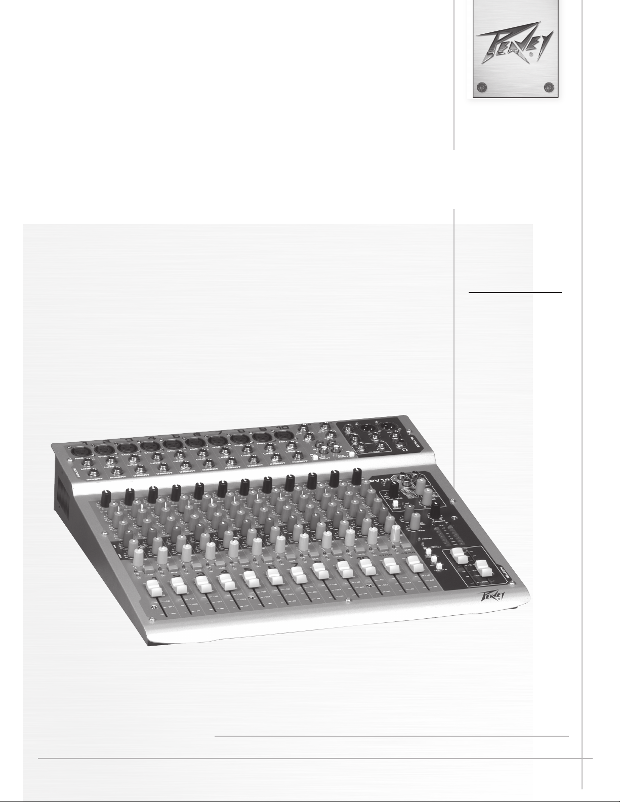
PV 20
www.peavey.com
PV
™
10 • PV
™
14 • PV
™
20
Compact Mixer
Operating
Manual
2
Intended to alert the user to the presence of uninsulated “dangerous voltage” within the product’s
enclosure that may be of sufficient magnitude to constitute a risk of electric shock to persons.
Intended to alert the user of the presence of important operating and maintenance (servicing)
instructions in the literature accompanying the product.
CAUTION: Risk of electrical shock — DO NOT OPEN!
CAUTION: To reduce the risk of electric shock, do not remove cover. No user serviceable parts inside.
Refer servicing to qualified service personnel.
WARNING: To prevent electrical shock or fire hazard, this apparatus should not be exposed to rain or
moisture‚ and objects filled with liquids‚ such as vases‚ should not be placed on this apparatus. Before
using this apparatus‚ read the operating guide for further warnings.
Este símbolo tiene el propósito, de alertar al usuario de la presencia de “(voltaje) peligroso” sin
aislamiento dentro de la caja del producto y que puede tener una magnitud suficiente como para
constituir riesgo de descarga eléctrica.
Este símbolo tiene el propósito de alertar al usario de la presencia de instruccones importantes sobre la
operación y mantenimiento en la información que viene con el producto.
PRECAUCION: Riesgo de descarga eléctrica ¡NO ABRIR!
PRECAUCION: Para disminuír el riesgo de descarga eléctrica, no abra la cubierta. No hay piezas útiles
dentro. Deje todo mantenimiento en manos del personal técnico cualificado.
ADVERTENCIA: Para prevenir choque electrico o riesgo de incendios, este aparato no se debe exponer a
la lluvia o a la humedad. Los objetos llenos de liquidos, como los floreros, no se deben colocar encima
de este aparato. Antes de usar este aparato, lea la guia de funcionamiento para otras advertencias.
Ce symbole est utilisé dans ce manuel pour indiquer à l’utilisateur la présence d’une tension dangereuse
pouvant être d’amplitude suffisante pour constituer un risque de choc électrique.
Ce symbole est utilisé dans ce manuel pour indiquer à l’utilisateur qu’il ou qu’elle trouvera d’importantes
instructions concernant l’utilisation et l’entretien de l’appareil dans le paragraphe signalé.
ATTENTION: Risques de choc électrique — NE PAS OUVRIR!
ATTENTION: Afin de réduire le risque de choc électrique, ne pas enlever le couvercle. Il ne se trouve
à l’intérieur aucune pièce pouvant être reparée par l’utilisateur. Confiez I’entretien et la réparation de
l’appareil à un réparateur Peavey agréé.
AVIS: Dans le but de reduire les risques d’incendie ou de decharge electrique, cet appareil ne doit
pas etre expose a la pluie ou a l’humidite et aucun objet rempli de liquide, tel qu’un vase, ne doit
etre pose sur celui-ci. Avant d’utiliser de cet appareil, lisez attentivement le guide fonctionnant pour
avertissements supplémentaires.
Dieses Symbol soll den Anwender vor unisolierten gefährlichen Spannungen innerhalb des Gehäuses
warnen, die von Ausreichender Stärke sind, um einen elektrischen Schlag verursachen zu können.
Dieses Symbol soll den Benutzer auf wichtige Instruktionen in der Bedienungsanleitung aufmerksam
machen, die Handhabung und Wartung des Produkts betreffen.
VORSICHT: Risiko — Elektrischer Schlag! Nicht öffnen!
VORSICHT: Um das Risiko eines elektrischen Schlages zu vermeiden, nicht die Abdeckung enfernen.
Es befinden sich keine Teile darin, die vom Anwender repariert werden könnten. Reparaturen nur von
qualifiziertem Fachpersonal durchführen lassen.
WARNUNG: Um elektrischen Schlag oder Brandgefahr zu verhindern, sollte dieser Apparat nicht
Regen oder Feuchtigkeit ausgesetzt werden und Gegenstände mit Flüssigkeiten gefuellt, wie Vasen,
nicht auf diesen Apparat gesetzt werden. Bevor dieser Apparat verwendet wird, lesen Sie bitte den
Funktionsführer für weitere Warnungen.
3
IMPORTANT SAFETY INSTRUCTIONS
WARNING: When using electrical products, basic cautions should always be followed, including the following:
1. Read these instructions.
2. Keep these instructions.
3. Heed all warnings.
4. Follow all instructions.
5. Do not use this apparatus near water.
6. Clean only with a dry cloth.
7. Do not block any of the ventilation openings. Install in accordance with manufacturer’s instructions.
8. Do not install near any heat sources such as radiators, heat registers, stoves or other apparatus (including amplifiers)
that produce heat.
9. Do not defeat the safety purpose of the polarized or grounding-type plug. A polarized plug has two blades with one
wider than the other. A grounding type plug has two blades and a third grounding plug. The wide blade or third prong is
provided for your safety. If the provided plug does not fit into your outlet, consult an electrician for replacement of the
obsolete outlet.
10. Protect the power cord from being walked on or pinched, particularly at plugs, convenience receptacles, and the point
they exit from the apparatus.
11. Only use attachments/accessories provided by the manufacturer.
12. Use only with a cart, stand, tripod, bracket, or table specified by the manufacturer, or sold with the apparatus. When a
cart is used, use caution when moving the cart/apparatus combination to avoid injury from tip-over.
13. Unplug this apparatus during lightning storms or when unused for long periods of time.
14. Refer all servicing to qualified service personnel. Servicing is required when the apparatus has been damaged in
any way, such as when power-supply cord or plug is damaged, liquid has been spilled or objects have fallen into the
apparatus, the apparatus has been exposed to rain or moisture, does not operate normally, or has been dropped.
15. Never break off the ground pin. Write for our free booklet “Shock Hazard and Grounding.” Connect only to a power
supply of the type marked on the unit adjacent to the power supply cord.
16. If this product is to be mounted in an equipment rack, rear support should be provided.
17. Note for UK only: If the colors of the wires in the mains lead of this unit do not correspond with the terminals in your
plug‚ proceed as follows:
a) The wire that is colored green and yellow must be connected to the terminal that is marked by the letter E‚ the earth
symbol‚ colored green or colored green and yellow.
b) The wire that is colored blue must be connected to the terminal that is marked with the letter N or the color black.
c) The wire that is colored brown must be connected to the terminal that is marked with the letter L or the color red.
18. This electrical apparatus should not be exposed to dripping or splashing and care should be taken not to place objects
containing liquids, such as vases, upon the apparatus.
19. Exposure to extremely high noise levels may cause a permanent hearing loss. Individuals vary considerably in suscep-
tibility to noise-induced hearing loss, but nearly everyone will lose some hearing if exposed to sufficiently intense noise
for a sufficient time. The U.S. Government’s Occupational Safety and Health Administration (OSHA) has specified the
following permissible noise level exposures:
Duration Per Day In Hours Sound Level dBA, Slow Response
8 90
6 92
4 95
3 97
2 100
1 1⁄2 102
1 105
1⁄2 110
1⁄4 or less 115
According to OSHA, any exposure in excess of the above permissible limits could result in some hearing loss. Earplugs or protectors to
the ear canals or over the ears must be worn when operating this amplification system in order to prevent a permanent hearing loss, if
exposure is in excess of the limits as set forth above. To ensure against potentially dangerous exposure to high sound pressure levels, it is
recommended that all persons exposed to equipment capable of producing high sound pressure levels such as this amplification system be
protected by hearing protectors while this unit is in operation.
SAVE THESE INSTRUCTIONS!
4
WICHTIGE SICHERHEITSHINWEISE
ACHTUNG: Beim Einsatz von Elektrogeräten müssen u.a. grundlegende Vorsichtsmaßnahmen befolgt werden:
1. Lesen Sie sich diese Anweisungen durch.
2. Bewahren Sie diese Anweisungen auf.
3. Beachten Sie alle Warnungen.
4. Befolgen Sie alle Anweisungen.
5. Setzen Sie dieses Gerät nicht in der Nähe von Wasser ein.
6. Reinigen Sie es nur mit einem trockenen Tuch.
7. Blockieren Sie keine der Lüftungsöffnungen. Führen Sie die Installation gemäß den Anweisungen des Herstellers durch.
8. Installieren Sie das Gerät nicht neben Wärmequellen wie Heizungen, Heizgeräten, Öfen oder anderen Geräten (auch Verstärkern),
die Wärme erzeugen.
9. Beeinträchtigen Sie nicht die Sicherheitswirkung des gepolten Steckers bzw. des Erdungssteckers. Ein gepolter Stecker weist
zwei Stifte auf, von denen einer breiter ist als der andere. Ein Erdungsstecker weist zwei Stifte und einen dritten Erdungsstift auf.
Der breite Stift bzw. der dritte Stift dient Ihrer Sicherheit. Sollte der beiliegende Stecker nicht in Ihre Steckdose passen, wenden
Sie sich bitte an einen Elektriker, um die ungeeignete Steckdose austauschen zu lassen.
10. Schützen Sie das Netzkabel, sodass niemand darauf tritt oder es geknickt wird, insbesondere an Steckern oder Buchsen und
ihren Austrittsstellen aus dem Gerät.
11. Verwenden Sie nur die vom Hersteller erhältlichen Zubehörgeräte oder Zubehörteile.
12. Verwenden Sie nur einen Wagen, Stativ, Dreifuß, Träger oder Tisch, der den Angaben des Herstellers entspricht oder zusammen
mit dem Gerät verkauft wurde. Wird ein Wagen verwendet, bewegen Sie den Wagen mit dem darauf befindlichen Gerät besonders
vorsichtig, damit er nicht umkippt und möglicherweise jemand verletzt wird.
13. Trennen Sie das Gerät während eines Gewitters oder während längerer Zeiträume, in denen es nicht benutzt wird, von der
Stromversorgung.
14. Lassen Sie sämtliche Wartungsarbeiten von qualifizierten Kundendiensttechnikern durchführen. Eine Wartung ist erforderlich,
wenn das Gerät in irgendeiner Art beschädigt wurde, etwa wenn das Netzkabel oder der Netzstecker beschädigt wurden,
Flüssigkeit oder Gegenstände in das Gerät gelangt sind, das Gerät Regen oder Feuchtigkeit ausgesetzt wurde, nicht normal
arbeitet oder heruntergefallen ist.
15. Der Erdungsstift darf nie entfernt werden. Auf Wunsch senden wir Ihnen gerne unsere kostenlose Broschüre „Shock Hazard and
Grounding“ (Gefahr durch elektrischen Schlag und Erdung) zu. Schließen Sie nur an die Stromversorgung der Art an, die am
Gerät neben dem Netzkabel angegeben ist.
16. Wenn dieses Produkt in ein Geräte-Rack eingebaut werden soll, muss eine Versorgung über die Rückseite eingerichtet werden.
17. Hinweis – Nur für Großbritannien: Sollte die Farbe der Drähte in der Netzleitung dieses Geräts nicht mit den Klemmen in Ihrem
Stecker übereinstimmen, gehen Sie folgendermaßen vor:
a) Der grün-gelbe Draht muss an die mit E (Symbol für Erde) markierte bzw. grüne oder grün-gelbe Klemme angeschlossen
werden.
b) Der blaue Draht muss an die mit N markierte bzw. schwarze Klemme angeschlossen werden.
c) Der braune Draht muss an die mit L markierte bzw. rote Klemme angeschlossen werden.
18. Dieses Gerät darf nicht ungeschützt Wassertropfen und Wasserspritzern ausgesetzt werden und es muss darauf geachtet
werden, dass keine mit Flüssigkeiten gefüllte Gegenstände, wie z. B. Blumenvasen, auf dem Gerät abgestellt werden.
19. Belastung durch extrem hohe Lärmpegel kann zu dauerhaftem Gehörverlust führen. Die Anfälligkeit für durch Lärm bedingten
Gehörverlust ist von Mensch zu Mensch verschieden, das Gehör wird jedoch bei jedem in gewissem Maße geschädigt, der über
einen bestimmten Zeitraum ausreichend starkem Lärm ausgesetzt ist. Die US-Arbeitsschutzbehörde (Occupational and Health
Administration, OSHA) hat die folgenden zulässigen Pegel für Lärmbelastung festgelegt:
Dauer pro Tag in Stunden Geräuschpegel dBA, langsame Reaktion
8 90
6 92
4 95
3 97
2 100
1
1
⁄
2
102
1 105
1
⁄
2
110
1
⁄
4
oder weniger 115
Laut OSHA kann jede Belastung über den obenstehenden zulässigen Grenzwerten zu einem gewissen Gehörverlust führen. Sollte
die Belastung die obenstehenden Grenzwerte übersteigen, müssen beim Betrieb dieses Verstärkungssystems Ohrenstopfen oder
Schutzvorrichtungen im Gehörgang oder über den Ohren getragen werden, um einen dauerhaften Gehörverlust zu verhindern. Um sich vor
einer möglicherweise gefährlichen Belastung durch hohe Schalldruckpegel zu schützen, wird allen Personen empfohlen, die mit Geräten
arbeiten, die wie dieses Verstärkungssystem hohe Schalldruckpegel erzeugen können, beim Betrieb dieses Geräts einen Gehörschutz zu tra-
gen.
BEWAHREN SIE DIESE SICHERHEITSHINWEISE AUF!
5
INSTRUCTIONS IMPORTANTES DE SECURITE
ATTENTION: L’utilisation de tout appareil électrique doit être soumise aux precautions d’usage incluant:
1. Lire ces instructions.
2. Gardez ce manuel pour de futures références.
3. Prétez attention aux messages de précautions de ce manuel.
4. Suivez ces instructions.
5. N’utilisez pas cette unité proche de plans d’eau.
6. N’utilisez qu’un tissu sec pour le nettoyage de votre unité.
7. N’obstruez pas les systèmes de refroidissement de votre unité et installez votre unité en fonction des instructions
de ce manuel.
8. Ne positionnez pas votre unité à proximité de toute source de chaleur.
9. Connectez toujours votre unité sur une alimentation munie de prise de terre utilisant le cordon d’alimentation
fourni.
10. Protégez les connecteurs de votre unité et positionnez les cablages pour éviter toutes déconnexions accidentelles.
11. N’utilisez que des fixations approuvées par le fabriquant.
12. Lors de l’utilsation sur pied ou pole de support, assurez dans le cas de déplacement de l’ensemble enceinte/
support de prévenir tout basculement intempestif de celui-ci.
13. Il est conseillé de déconnecter du secteur votre unité en cas d’orage ou de durée prolongée sans utilisation.
14. Seul un technicien agréé par le fabriquant est à même de réparer/contrôler votre unité. Celle-ci doit être contrôlée si
elle a subit des dommages de manipulation, d’utilisation ou de stockage (humidité,…).
15. Ne déconnectez jamais la prise de terre de votre unité.
16. Si votre unité est destinée a etre montée en rack, des supports arriere doivent etre utilises.
17. Note pour les Royaumes-Unis: Si les couleurs de connecteurs du cable d’alimentation ne correspond pas au guide
de la prise secteur, procédez comme suit:
a) Le connecteur vert et jaune doit être connectrer au terminal noté E, indiquant la prise de terre ou correspondant
aux couleurs verte ou verte et jaune du guide.
b) Le connecteur Bleu doit être connectrer au terminal noté N, correspondnat à la couleur noire du guide.
c) Le connecteur marron doit être connectrer au terminal noté L, correspondant à la couleur rouge du guide.
18. Cet équipement électrique ne doit en aucun cas être en contact avec un quelconque liquide et aucun objet
contenant un liquide, vase ou autre ne devrait être posé sur celui-ci.
19. Une exposition à de hauts niveaux sonores peut conduire à des dommages de l’écoute irréversibles. La suscep-
tibilité au bruit varie considérablement d’un individu à l’autre, mais une large majorité de la population expériencera
une perte de l’écoute après une exposition à une forte puissance sonore pour une durée prolongée. L’organisme de
la santé américaine (OSHA) a produit le guide ci-dessous en rapport à la perte occasionnée:
Durée par Jour (heures) Niveau sonore moyen (dBA)
8 90
6 92
4 95
3 97
2 100
1
1
⁄
2
102
1 105
1
⁄
2
110
1
⁄
4
ou inférieur 115
D’après les études menées par le OSHA, toute exposition au delà des limites décrites ce-dessus entrainera des pertes de l’écoute chez la
plupart des sujets. Le port de système de protection (casque, oreilette de filtrage,…) doit être observé lors de l’opération cette unité ou des
dommages irréversibles peuvent être occasionnés. Le port de ces systèmes doit être observé par toutes personnes susceptibles d’être expo-
sées à des conditions au delà des limites décrites ci-dessus.
GARDEZ CES INSTRUCTIONS!
6
INSTRUCCIONES IMPORTANTES PARA SU SEGURIDAD
CUIDADO: Cuando use productos electrónicos, debe tomar precauciones básicas, incluyendo las siguientes:
1. Lea estas instrucciones.
2. Guarde estas instrucciones.
3. Haga caso de todos los consejos.
4. Siga todas las instrucciones.
5. No usar este aparato cerca del agua.
6. Limpiar solamente con una tela seca.
7. No bloquear ninguna de las salidas de ventilación. Instalar de acuerdo a las instrucciones del fabricante.
8. No instalar cerca de ninguna fuente de calor como radiadores, estufas, hornos u otros aparatos (incluyendo amplificadores)
que produzcan calor.
9. No retire la patilla protectora del enchufe polarizado o de tipo “a Tierra”. Un enchufe polarizado tiene dos puntas, una de
ellas más ancha que la otra. Un enchufe de tipo “a Tierra” tiene dos puntas y una tercera “a Tierra”. La punta ancha (la
tercera ) se proporciona para su seguridad. Si el enchufe proporcionado no encaja en su enchufe de red, consulte a un
electricista para que reemplaze su enchufe obsoleto.
10. Proteja el cable de alimentación para que no sea pisado o pinchado, particularmente en los enchufes, huecos, y los puntos
que salen del aparato.
11. Usar solamente añadidos/accesorios proporcionados por el fabricante.
12. Usar solamente un carro, pie, trípode, o soporte especificado por el fabricante, o vendido junto al aparato. Cuando se use
un carro, tenga cuidado al mover el conjunto carro/aparato para evitar que se dañe en un vuelco. No suspenda esta caja de
ninguna manera.
13. Desenchufe este aparato durante tormentas o cuando no sea usado durante largos periodos de tiempo.
14. Para cualquier reparación, acuda a personal de servicio cualificado. Se requieren reparaciones cuando el aparato ha sido
dañado de alguna manera, como cuando el cable de alimentación o el enchufe se han dañado, algún líquido ha sido
derramado o algún objeto ha caído dentro del aparato, el aparato ha sido expuesto a la lluvia o la humedad, no funciona de
manera normal, o ha sufrido una caída.
15. Nunca retire la patilla de Tierra.Escríbanos para obtener nuestro folleto gratuito “Shock Hazard and Grounding” (“Peligro
de Electrocución y Toma a Tierra”). Conecte el aparato sólo a una fuente de alimentación del tipo marcado al lado del cable
de alimentación.
16. Si este producto va a ser enracado con más equipo, use algún tipo de apoyo trasero.
17. Nota para el Reino Unido solamente: Si los colores de los cables en el enchufe principal de esta unidad no corresponden
con los terminales en su enchufe‚ proceda de la siguiente manera:
a) El cable de color verde y azul debe ser conectado al terminal que está marcado con la letra E‚ el símbolo de Tierra
(earth)‚ coloreado en verde o en verde y amarillo.
b) El cable coloreado en azul debe ser conectado al terminal que está marcado con la letra N o el color negro.
c) El cable coloreado en marrón debe ser conectado al terminal que está marcado con la letra L o el color rojo.
18. Este aparato eléctrico no debe ser sometido a ningún tipo de goteo o salpicadura y se debe tener cuidado para no poner
objetos que contengan líquidos, como vasos, sobre el aparato.
19. La exposición a altos niveles de ruido puede causar una pérdida permanente en la audición. La susceptibilidad a la pérdida
de audición provocada por el ruido varía según la persona, pero casi todo el mundo perderá algo de audición si se expone
a un nivel de ruido suficientemante intenso durante un tiempo determinado. El Departamento para la Salud y para la
Seguridad del Gobierno de los Estados Unidos (OSHA) ha especificado las siguientes exposiciones al ruido permisibles:
Duración por Día en Horas Nivel de Sonido dBA, Respuesta Lenta
8 90
6 92
4 95
3 97
2 100
1
1
⁄
2
102
1 105
1
⁄
2
110
1
⁄
4
o menos 115
De acuerdo al OSHA, cualquier exposición que exceda los límites arriba indicados puede producir algún tipo de pérdida en la audición.
Protectores para los canales auditivos o tapones para los oídos deben ser usados cuando se opere con este sistema de sonido para preve-
nir una pérdida permanente en la audición, si la exposición excede los límites indicados más arriba. Para protegerse de una exposición a
altos niveles de sonido potencialmente peligrosa, se recomienda que todas las personas expuestas a equipamiento capaz de producir altos
niveles de presión sonora, tales como este sistema de amplificación, se encuentren protegidas por protectores auditivos mientras esta uni-
dad esté operando.
GUARDE ESTAS INSTRUCCIONES!

7
PV
™
10, PV
™
14 and PV
™
20
Compact Mixers
Congratulations on purchasing the Peavey PV
™
10, PV
™
14, or the PV
™
20 Compact Mixer. The PV
™
10, PV
™
14, and PV
™
20 are
studio-quality mixing consoles designed to meet diverse needs while occupying a small space. These are the perfect
consoles for small venue performances or home recording environments. PV series mixers feature built-in DSP effects that are
useful in real-world recording and sound reinforcement, while parameter controls allow you to tailor each effect to meet your
needs.
Please read this guide carefully to ensure your personal safety as well as the safety of your equipment.
FEATURES:
• Six XLR mic inputs on PV
™
10, ten XLR mic inputs on PV
™
14, and sixteen XLR mic inputs on the PV
™
20
• Two stereo channels with RCA and 1/4" inputs
• Three-band channel EQ
• A/B stereo input selector reduces patching
• Inserts on all mono channels
• 80 Hz low-cut switch on all mic inputs
• USB connectivity (standard on the PV
™
20, optional on both PV
™
10 & PV
™
14)
• Clip LEDs monitor the entire signal path for clipping
• Signal LEDs on every input channel
• Mute switches with LED indicator on every input channel
• 48 Volt phantom power switch
• Effects send on every channel with stereo return
• Internal digital effects with 16 selections, including reverb, delay and vocal enhancement
• Effect parameter adjustment allows you to customize each effect selection
• Monitor send on every channel
• Zero latency record monitoring capabilities
• Control room output with level control
• Contour EQ switch
• Internal universal input power supply
• Optional rack-mount kit (PV
™
10 and PV
™
14 Only)
ENGLISH
Installation Note:
This unit must have the following clearances from any combustible surface: top: 8", sides: 12", back: 12"
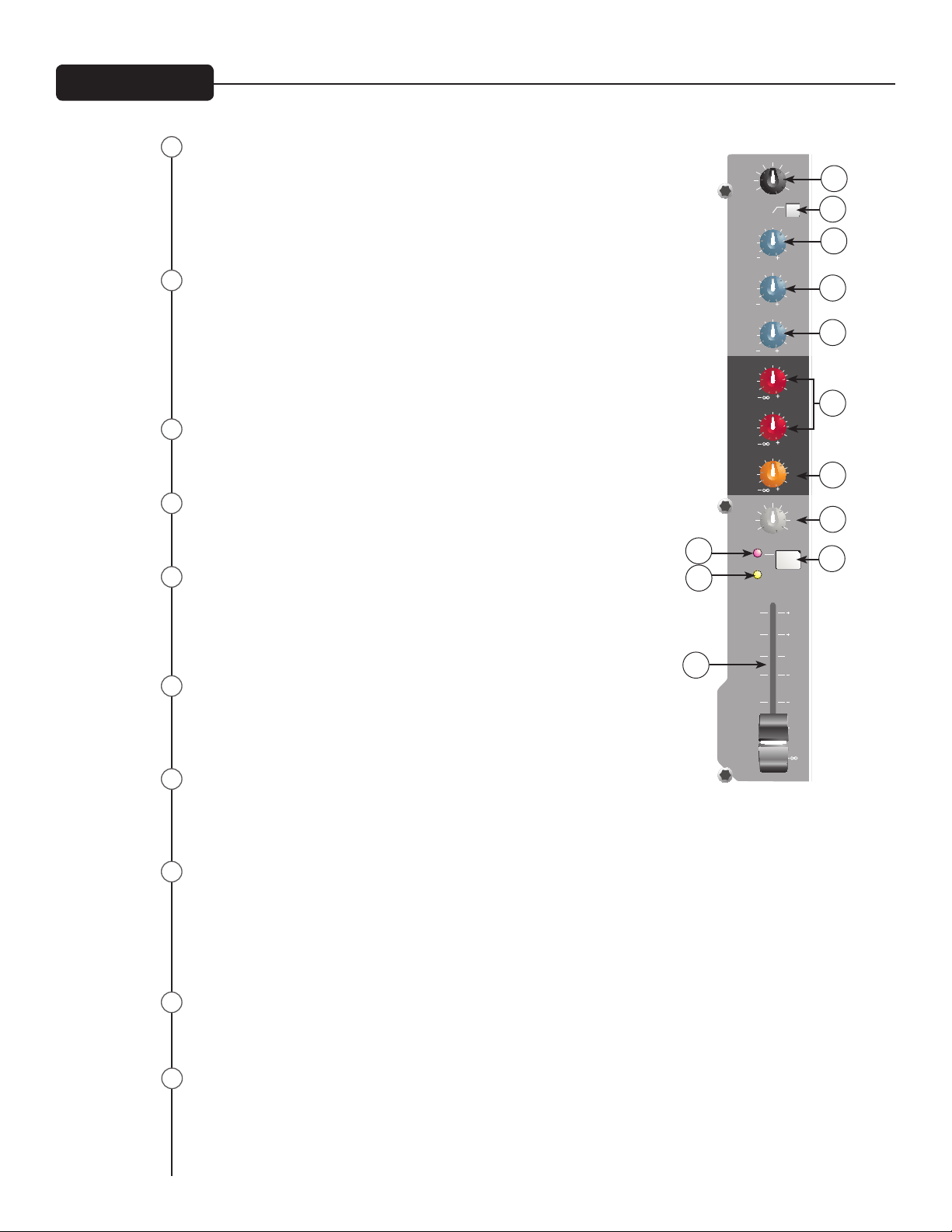
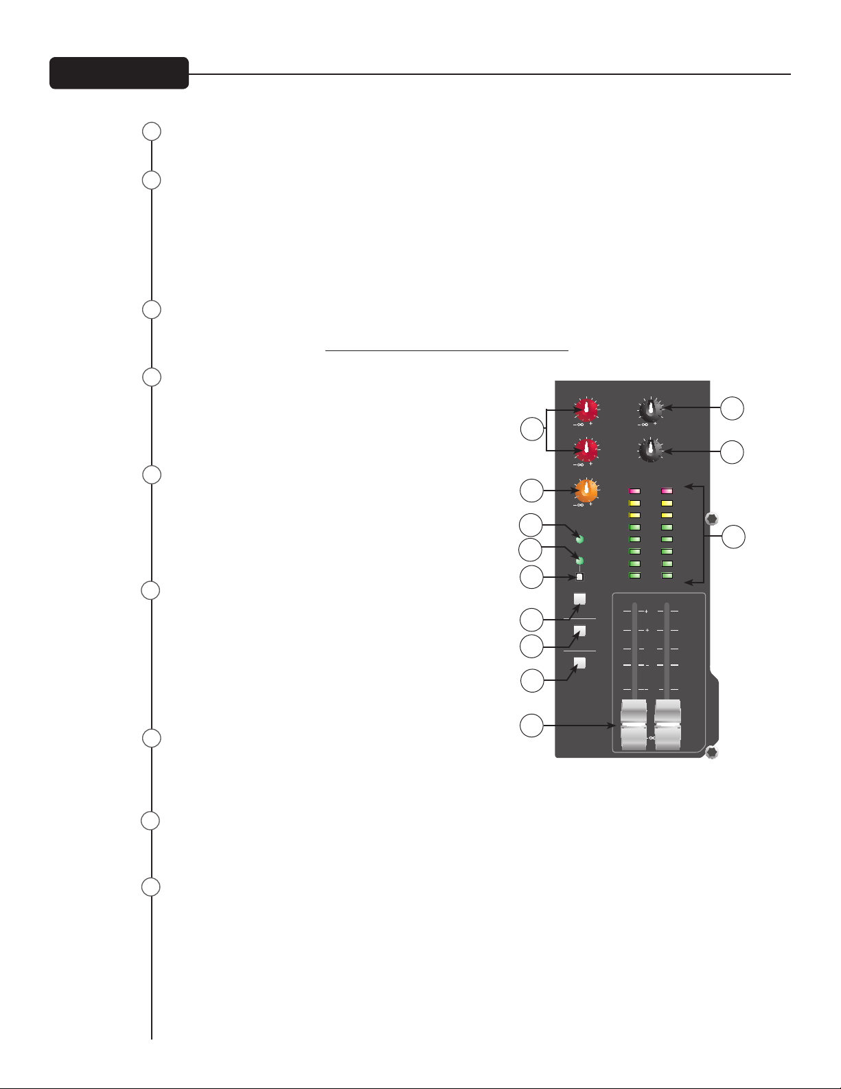
Gain
This control establishes the nominal operating level for the channel.
The input gain can be adjusted over a wide range to compensate for soft
voices or very loud drums. To maximize the signal-to-noise ratio, the gain
should be set to the proper level, with the channel Fader (12) set to 0. If
the clip LED comes on and remains lit, try reducing the gain.
80 Hz Low Cut
The low cut lter has a corner frequency of 80 Hz. When engaged‚ it
can improve clarity by removing low frequencies that make a mix sound
muddy. This feature is especially useful when playing outside on a windy
day or on a hollow-sounding‚ noisy stage. These kinds of ambient noises
can rob your sound system of power. Engaging this switch will remove
those frequencies from the system and restore power where needed.
Hi EQ
This active tone control (shelving type: ±15 dB) varies the level of the high
frequency range.
Mid EQ
This active tone control (peak dip: ±15 dB) varies the level of the mid
frequency range.
Low EQ
This active tone control (shelving type: ±15 dB) varies the level of the low
frequency range.
Caution: Excessive low frequency boost causes greater power consump-
tion and increases the possibility of speaker damage.
MON Send (MON Send 2 on the PV
™
20 only)
This control adjusts the level of the channel signal sent to the monitor
output. The signal is taken before the channel Fader (12) but after the
channel EQ.
EFX Send
This control adjusts the level of the channel signal added to the effects
mix. The effects send signal is taken after the channel Fader (12) so that adjustments made to the fader
will also affect the send level.
Pan
This knob controls the placement of the signal in the stereo eld. When rotated completely counter-
clockwise‚ the signal is present only on the left channel; when rotated completely clockwise‚ only in the
right channel. This control functions as a balance control to adjust the relative level of the left and right
signals on stereo channels 5/6 and 7/8 on the PV
™
10 (11/12 and 13/14 on the PV
™
14, 17/18 and 19/20
on the PV
™
20).
Mute
The mute button is a quick way to remove the channel signal from the left/right main mix, as well as
effects and monitor sends, without disturbing the control settings.
Clip/Mute LED
This light normally indicates that the channel signal level is nearing the overload point, but it also lights
when mute is engaged. The clip indicator circuit monitors the signal at many points in the channel to
ensure that it catches all instances of clipping. It illuminates at +19 dBu and warns that the gain or EQ
boost should be reduced. When it lights, roughly 3 dB of headroom remains.
PREPOST P RE
HI
(dB)
12
0
15 15
12
9
9
6
6
3
3
(dB)
MID
12
0
15 15
12
9
9
6 6
33
GAIN
9
5
0 10
1
8
2
3
7
6
4
LOW
12
0
15 15
12
9
9
6 6
3
3
(dB)
PAN
R
L
C
EFX
10
0
5
3
3
40
15
6
10
0
5
3
3
40
15
6
MON
1
80 HZ
MUTE
CLIP
SIG
1
10
6
0
6
12
20
10
0
5
3
3
40
15
6
MON
2
dB
dB
dB
1
2
3
4
5
7
8
9
10
12
8
Front Panel
1
2
3
4
7
9
5
6
8
10
11
6
Signal LED
The signal LED lights when the channel level reaches approxi-
mately -20 dBu. This not only indicates which channels are
active, but also serves as a mini level meter.
Fader
The channel Fader is the channel output control, which sets
the signal level to the left and right mix and the effects send
control. The optimum setting is the 0 (unity gain) position.
Tape In/Out
The tape input jacks are designed to accommodate tape‚ CD,
or computer sound card output levels. The output level is +4
dBu for connecting to a recorder or sound card input. The tape
inputs can be used as an additional stereo input by engaging
the Tape/USB to Main Mix switch (27). The tape input can also be used to monitor the recorder/sound
card output without the risk of feedback.
NOTE: The USB input is routed to the Tape Input left/right. If another device is connected to the Tape
Input, this signal will be combined with the USB input signal.
EFX Select
This rotary switch selects one of sixteen available effects. As shown in the table below.
EFX
10
0
6
3
2
40
10
4
TIME
EFX
DEFEAT
9
5
0 10
1
8
2
3 7
64
CLIP
SIGNAL
PV20
L
R
L
R
TAPE
OUT
TAPE
IN
dB
VOC ENH2
VOC ENH1
SHIMMER
DOUBLER
TAPE DELAY
DELAY 3
DELAY 2
DELAY 1
HALL REV
L HALL REV
RM1 REV
RM2 REV
PLT1 REV
PLT2 REV
CATHEDRAL
SPRING
USB
HEADPHONE
13
14
15
16
18
17
Effect
Description Application Parameter
1 Hall Rev Medium Concert Hall Ensemble Rev Time
2 Large Hall Rev Larger Concert Hall Darker Gen Reverb Rev Time
3 Room 1 Rev Intimate Room Bright Pop Vocal Rev Time
4 Room 2 Rev Larger Room Darker Drums, Rhythm Rev Time
5 Plate 1 Rev Bright Pop Vocal Rev Time
6 Plate 2 Rev Darker Drums Rev Time
7 Cathedral Large Space, Long and Darker Choir Rev Time
8 Spring Classic Spring Guitar Rev Time
9 Delay 1 Single Delay (Slap-back) Voc/Inst Dly Time
10 Delay 2 Warm Delay with Repeats Instruments Dly Time
11 Delay 3 Dark Delay with Repeats Instruments Dly Time
12 Tape Delay Warm Delay Instruments Dly Time/Feedback
13 Doubler Single Delay, 30-120 ms Instruments Dly Time
14 Shimmer Warm Delay with Modulation Instruments Dly Time
15 Vocal Enhancement 1 Brightens and Adds Room Reverb Vocals Rev Level
16 Vocal Enhancement 2 Brightens and Adds Spring Reverb Vocals Rev Level
9
Front Panel
11
12
13
15
14
10
EFX Time
This control adjusts the time of the particular reverb or delay.
Green Signal LED and Red Clip LED
The green Signal LED and red Clip LED are used to set the operating input level to the PV™10, PV™14,
and PV™20 effects processors. The signal level to the processor is affected by channel Fader, the Effects
Send and the Effects Send Master Controls. Start with the Master Control (20) set to 0 (12 o’clock) and
adjust the channel sends so that the signal LED lights and the clip LED blinks on occasionally, if at all.
The clip LED lights 6 dB below clipping. Pressing the EFX defeat mutes the effects signal and lights the
clip/mute LED.
EFX Return
Once the input level is set (see 17) use the EFX Return control to mix the effects processor output into
the main left/right outputs. Remember, a little reverb goes a long way.
MON Send Master
This is the master output level control for the monitor mix.
The output level sent to the Monitor Send jack (37) is con-
trolled by the channel Monitor Send controls (6) and by this
master control.
EFX Send Master
This is the master output level control for the EFX mix. The
output level sent to the EFX Send jack and the internal ef-
fects processor is controlled by the channel Fader (12), the
channel EFX Send controls (7), and by this master control.
The 0 position is the recommended setting for this control.
Headphone Level
This knob sets the headphone and control room output
levels. To avoid damage to your hearing‚ make sure to turn
the dial fully counterclockwise before using headphones.
Slowly turn the knob clockwise until you reach a comfort-
able listening level. Normally, the signal in the headphones
is the left/right signal. If the Tape to Control Room (26) is
engaged‚ the tape signal is also included.
LED Meters
Two eight-segment LED arrays are provided to monitor the
levels of the main left/right outputs. These meters range
from -30 dB to +19 dB. The 0 dB position on the meter corresponds to +4 dBu at the outputs.
Power LED
This LED indicates AC power is supplied to the unit‚ the power switch is on, and the unit is functioning
properly.
Phantom Power LED
This LED lights when the Phantom Power Switch (25) has been engaged.
MAS TER
10
0
5
3
3
40
15
6
10
0
5
3
3
40
15
6
EFX
SEND
MON1
SEND
TAPE/ USB TO
CTRL/ HP
TAPE/ USB
TO MI X
POWER
CONTO UR
MASTER LEVEL
L R
CLIP
+6
0
-3
-6
-12
-20
-30
+48V
PHANT OM
dB
dB
10
6
0
6
12
20
USB
EQUIP PED
10
0
5
3
3
40
15
6
MON2
SEND
dB
9
5
0 10
1
8
2
3 7
64
HEADPHONE
10
0
5
3
3
40
15
6
TAPE/USB
TO MAIN
dB
20
21
25
26
27
30
22
Front Panel
17
22
19
20
21
24
23
18
19
23
24
29
16
28
11
Phantom Power Switch
This Switch applies +48 VDC voltage to the input XLR connectors to power microphones requiring phan-
tom power.
If phantom power is used, do not connect unbalanced dynamic microphones or other devices to the XLR
inputs.
Tape To CTRL/HP
Depressing this switch adds the tape return to the Control Room (39) and Headphone Outputs (41) for
zero latency monitoring.
Tape/to Mix (Tape/USB to Mix)
Depressing this switch routes the signal from the Tape Inputs (13) or USB Input (44) to the Left/Right
Outputs (40). The USB input level is controlled by the computer volume control.
Tape/USB to Main (PV
™
20 only)
This knob provides a convenient way to adjust the Tape Input (13) or USB Input (44) volume. (On models
PV
™
10 and PV
™
14, adjust the USB Input (44) volume with the computer volume control.)
Contour Switch
Engaging this switch enhances the signal by adding both bass and treble frequencies. This is especially
effective at lower volumes or for tape/CD playback.
Master Level Faders
These Master Faders control the levels sent to the main left/right outputs. Best results are obtained
when these controls are set near the 0 point.
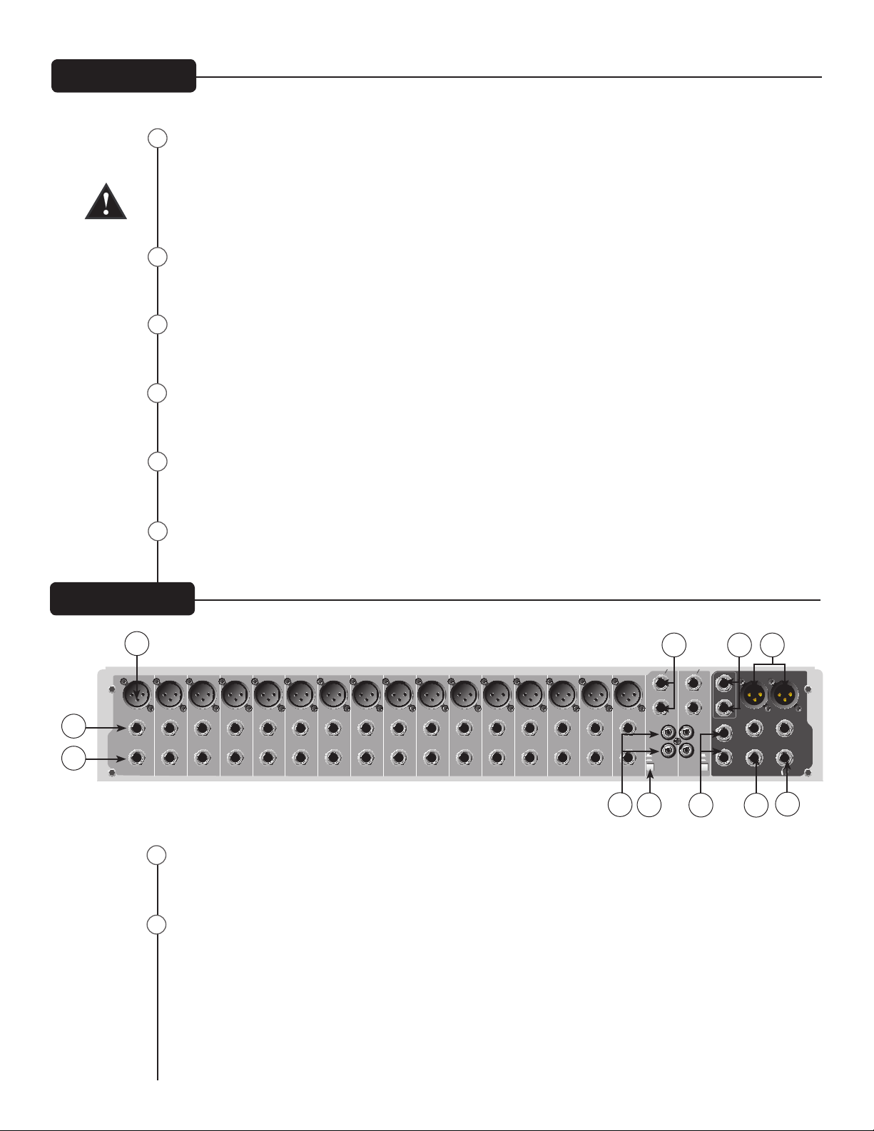
Mic (XLR) Inputs
XLR balanced inputs are optimized for a microphone or other low impedance source. Pin 2 is the positive
input. Because of the wide range of gain adjustment, signal levels up to +14 dBu can be accommodated.
Line (1⁄4”) Inputs
Line inputs provide 1⁄4” balanced (TRS) 10 k Ohm impedance input. The tip is the positive input and
should be used for unbalanced inputs. It has 20 dB less gain than the XLR input and does not have
phantom power available. The Mic and Line inputs should not be used simultaneously.
Front Panel
26
27
28
29
25
32
11 12
13
14
19 20
15
16
17 18
OUTPU TS
MIC MIC MIC MIC
L/
MONO
L/
MONO
R R
LINE
INSER T
LINE
INSER T
LINE
INSER T
LINE
INSER T
L
R
L
R
A/B
INPUT
A/B
INPUT
B
A
B
A
A A
BB
MIC
LINE
INSER T
MIC
LINE
INSER T
LEFT OUT RIGHT OUT
BAL BAL BAL BAL BAL BAL
7 8 9 10
INPUT S
MIC MIC MIC MIC
LINE
INSER T
LINE
INSER T
LINE
INSER T
LINE
INSER T
BAL BAL BAL BAL
MON 2 SEND
EFX SEND
L
R
CTRL/ROOM
MON 1 SEND
6
MIC
LINE
INSER T
BAL
5
MIC
LINE
INSER T
BAL
4
MIC
LINE
INSER T
BAL
3
MIC
LINE
INSER T
BAL
2
MIC
LINE
INSER T
BAL
1
MIC
LINE
INSER T
BAL
31
32
33
34
35
36
37
38
41
4039
Rear Panel
30
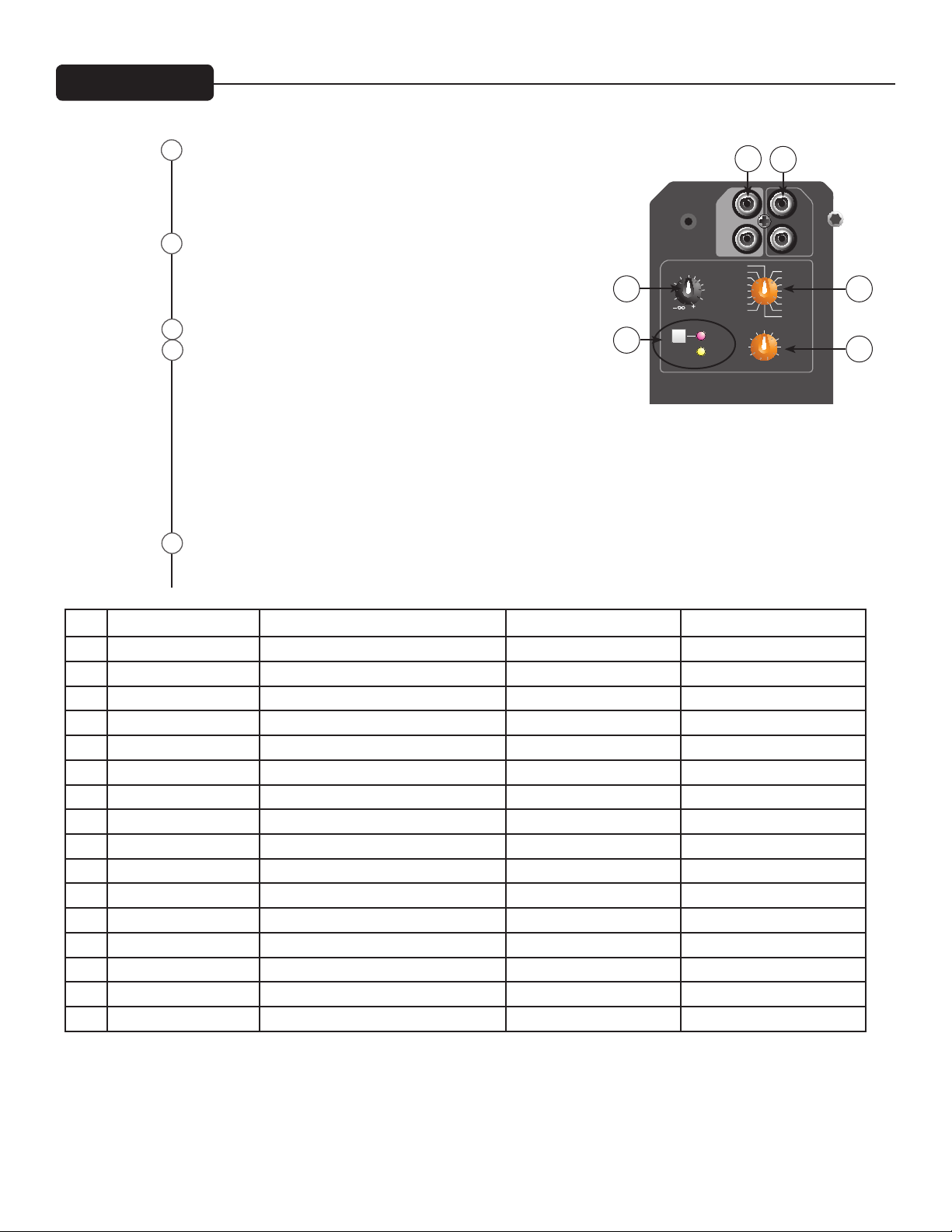
31

Insert
The 1⁄4” TRS connectors allow external signal processors to be inserted into the channel signal path.
Tip=Send; Ring=Return; Sleeve=Ground.
Stereo (1⁄4”) Inputs
These 1⁄4” unbalanced inputs work as a stereo line input using both jacks or as a mono input if the con-
nection is made to the left/mono input only. The A/B input selector must be in the “A” position for these
jacks to be active.
RCA Inputs
These RCA inputs work as stereo line inputs. The A/B input selector must be in the “B” position for
these jacks to be active.
A/B Switch
The A/B input selector switch expands the capability of the PV™10, PV™14, and the PV™20 mixers by
allowing two stereo sources to be connected to each stereo line input. Instead of repatching, the switch
selects which input jacks are active.
MON Send
The MON Send features a 1⁄4” TRS Z-balanced jack in the master section. This output can be used with
the Tip, Ring, Sleeve (TRS) balanced or Tip, Sleeve (TS) unbalanced connectors. The MON mix is deter-
mined by the amount of signal being sent to the MON bus in each channel and by the Monitor Master
control (19).
EFX Send
The EFX Send features a 1⁄4” TRS Z-balanced jack in the master section. These outputs can be used with
Tip‚ Ring, Sleeve (TRS) balanced, or Tip, Sleeve (TS) unbalanced connectors. The EFX mix is determined
by the amount of signal being sent to the EFX bus in each channel and by the EFX master control.
Control Room Outputs
The Control Room outputs feature two 1⁄4” TRS Z-balanced jacks. These outputs can be used with Tip,
Ring, Sleeve (TRS) balanced, or Tip, Sleeve (TS) unbalanced connectors. The Control Room output level
is adjusted with the Headphone level control (21).
Left/Right Outputs
The left/right Outputs feature two 1⁄4” TRS Z-balanced jacks and two fully balanced XLR outputs. The
1⁄4” outputs can be used with Tip‚ Ring, Sleeve (TRS) balanced or Tip, Sleeve (TS) unbalanced connec-
tors. The output level is set by the Master Level Faders (30). Both outputs can be used simultaneously.
Headphone Output
The Headphone Output is a 1⁄4” TRS (Tip= Left; Ring = Right; Sleeve = Ground). The signal sent to this
output is normally the left/right mix. When the Tape to Control Room switch is engaged, the tape input
signal is added to the left/right mix and can be monitored in the headphones.
12
Rear Panel
34
35
37
36
38
40
39
33
41
13
A PRODUCT OF
PEAVEY ELECTRONICS CORP.
DESIGNED IN USA MADE IN CHINA
peavey.com
POWER
R
S
T
(POS)
(NEG)
(GND)
BALANCED
UNBALANCED
S
T
(POS)
(GND)
ON
1 - GROUND
2 - POSITIVE
3 - NEGATIVE
1 - GROUND
2 - POSITIVE
3 - NEGATIVE
INPUT
OUTPUT
27 WATTS
100 - 240V 50/60 Hz
TRS INSERT
TIP
RING
SLEEVE
TIP = SND
RING = RET
SLEEVE = GND
CAUTION
TO REDUCE THE RISK OF FIRE OR ELECTRIC SHOCK, THIS APPARATUS
WARNING:
SHOULD NOT BE EXPOSED TO RAIN OR MOISTURE AND OBJECTS FILLED WITH LIQUIDS,
SUCH AS VASES, SHOULD NOT BE PLACED ON THIS APPARATUS.
AVIS:
ELECTRIQUE, CET APPAREIL NE DOIT PAS ETRE EXPOSE A LA PLUIE OU A L’HUMIDITE ET
AUCUN OBJET REMPLI DE LIQUIDE, TEL QU’UN VASE, NE DOIT ETRE POSE SUR CELUI-CI.
DANS LE BUT DE REDUIRE LES RISQUES D’INCENDIE OU DE DECHARGE
RECORD
LEVEL
COMPUT ER
DIGITAL AUDIO
PORT
MIN
42
43
Rear Panel
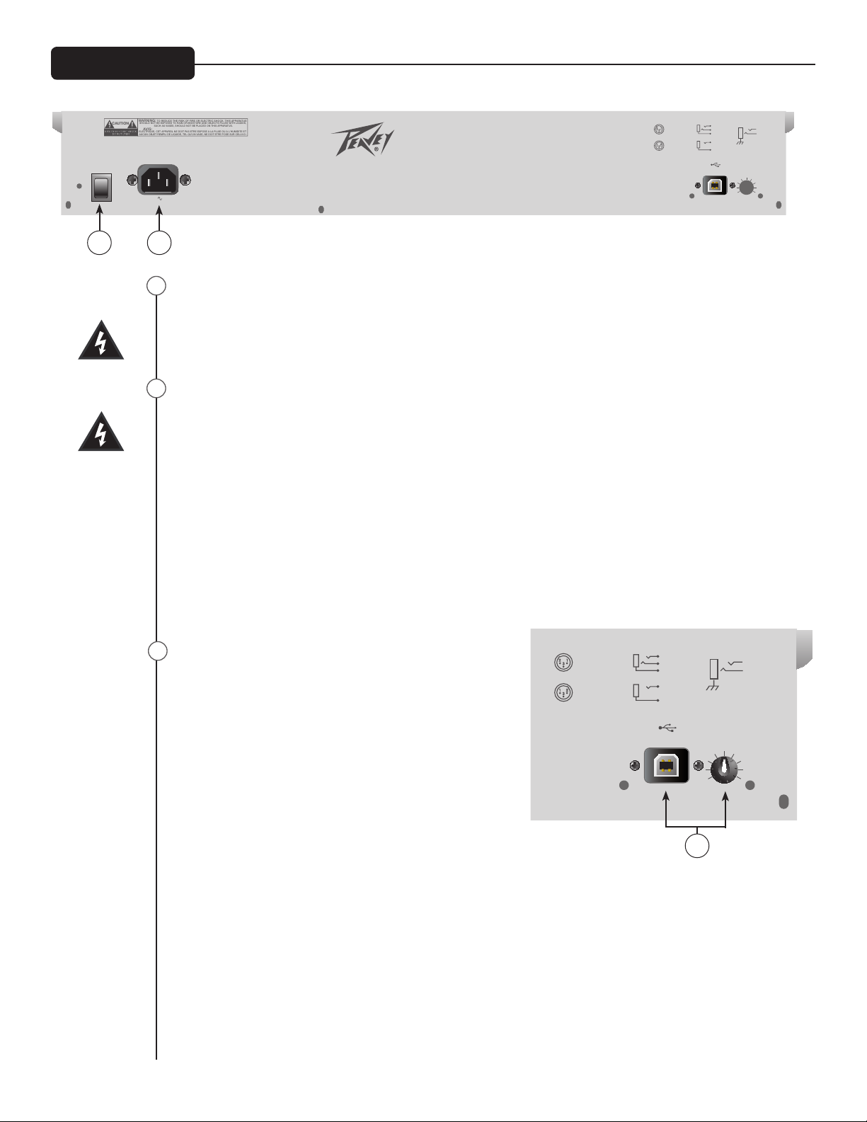
Power Switch
Depressing the power switch supplies power to the unit.
Warning: The power switch in this unit breaks only one side of the line. Hazardous energy may be
present inside the mixer when the power switch is in the OFF position.
Removable Power Cord
This receptacle is for the IEC line cord (included) that provides AC power to the unit. Connect the line
cord to this connector and to a properly grounded AC supply. Damage to the equipment may occur if an
improper line voltage is used (see voltage marking on unit). Never remove or cut the ground pin of the
line cord plug. The console is supplied with a properly rated line cord. If lost or damaged, replace this
cord with one of the proper rating.
NOTE FOR UK ONLY:
If the colors of the wires in the mains lead of this unit do not correspond with the colored markings iden-
tifying terminals in your plug, proceed as follows: (1) The wire that is colored green and yellow must be
connected to the terminal marked by the letter E, or by the earth symbol, or colored green or green and
yellow. (2) The wire that is colored blue must be connected to the terminal that is marked with the letter
N, or colored black. (3) The wire that is colored brown must be connected to the terminal that is marked
with the letter L or colored red.
USB port and USB Record Level Control
The USB port is used to connect the PV™ Series USB mixer to
acomputer for recording or playing back digital audio to/from
your computer. The USB port sends the mixer’s main/tape
stereo out to the computer. The amount of the main mix
signal being sent to the USB port can be adjusted using the
Record Level control located next to the USB port. The USB
port receives digital audio from the computer; it can then be
assigned through the “Tape/USB to Mix” switch (27) to the
main left/right output. The USB input level is controlled by
the computer volume control.
Compatible with Windows
®
XP, ME & 2000. Also compatible
with Mac OS X
®
10.0 or later.
43
R
S
T
(POS)
(NEG)
(GND)
BALANCED
UNBALANCED
S
T
(POS)
(GND)
1 - GROUND
2 - POSITIVE
3 - NEGATIVE
1 - GROUND
2 - POSITIVE
3 - NEGATIVE
INPUT
OUTPUT
TRS INSERT
TIP
RING
SLEEVE
TIP = SND
RING = RET
SLEEVE = GND
RECORD
LEVEL
COMP UTER
DIGI TAL AU DIO
POR T
MIN
44
44
42
14
Meridian, MS 39301
Peavey Electronics Corp.
P. O. Box 2898
Sheet Title:
Title:
Sheet
Date:
of
B
A
21
C
CONTOUR
LO HI
4
+48V
+
-
CONTOUR
LO HI
PAN
EQ
LO MID HI
EQ
LO MID HI
EQ
LO MID HI
80Hz
BALANCE
B
RIGHT
TAPE -L/R SELECT
POWER
PHANTOM
LINE
RIGHT
LEFT
XLR
TAPE OUTPUT
GLOBAL
CONTROL ROOM
TAPE TO
GAIN
EFX
EFX
LEFT/MONO
RIGHT
LEFT
SELECT
INPUT
LED METER
EFX RETURN
INSERT
3-BAND EQ
LEVEL
CLIP/MUTE
CLIP/MUTE
EFX
DIGITAL
DEFEAT
EFX
EFX
SELECTOR
RETURN
EFX
ADJUST
TIME
MUTE
CLIP/
SIGNAL
MUTE
MUTE
EFX SEND
A
A/B
LEFT
RIGHT
LOW-CUT
CHANNEL 1-6 (PV10)
MONO INPUT
CHANNEL 1-10 (PV14)
CHANNEL 1-16 (PV20)
CHANNEL 7/8 - 9/10 (PV10)
STEREO INPUT
CHANNEL 11/12 - 13/14 (PV14)
CHANNEL 17/18 - 19/20 (PV20)
MON1
MON2
MON1
MON2
EFX
MON 1 SEND
MON 2 SEND
LEFT/MONO
RIGHT
TAPE INPUT
DIGITAL AUDIO PORT
MON 1
MON 2
RIGHT
LEFT
MAIN OUTPUTS
HEADPHONES
CONTROL ROOM
USB
USB OUT
USB IN
USB MODELS ONLY
TAPE TO MIX
PV20 ONLY
PV 20 ONLY
PV 20 ONLY
2
3
1
PV14_BLOCK
6-13-2005_13:552 2
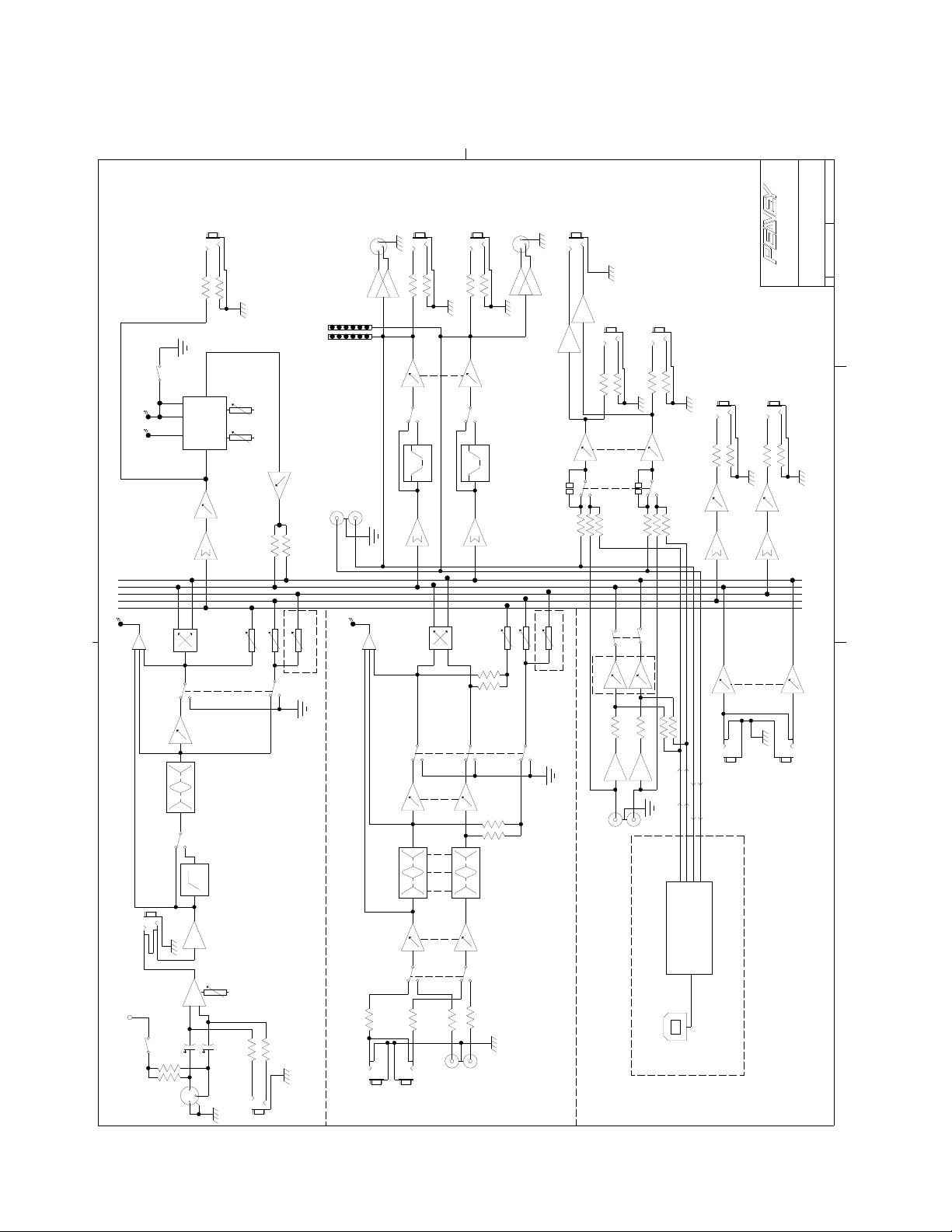
Block Diagram-PV
™
10, PV
™
14 & PV
™
20
15
PV
™
10, PV
™
14 & PV
™
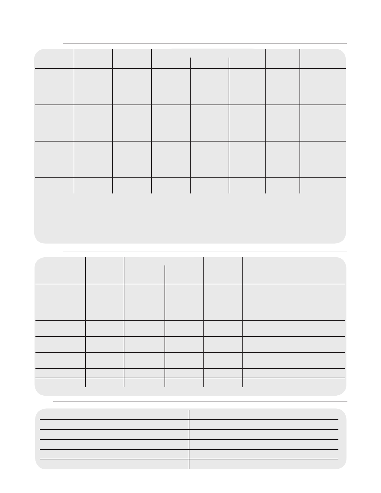
20 Series Specications
Inputs
Function Input Z
(ohms min)
Input Gain
Setting Min** Nominal* Max
Bal/
Unbal
Connector
Microphone
(150 ohms)
2.2k Max Gain
(60 dB)
Min Gain
(10 dB)
-76 dBu
-24 dBu
-56 dBu
-4 dBu
-38 dBu
+14 dBu
Bal XLR Pin 1 Gnd
Pin 2 (+)
Pin 3 (-)
Line
(10 k ohms)
10k Max Gain
(40 dB)
Min Gain
(-10 dB)
-56 dBu
-10 dBu
-36 dBu
+14 dBu
-18 dBu
+32 dBu
Bal 1/4" TRS;
Tip (+)
Ring (-)
Sleeve Ground
Stereo Line
Input
10k Max Gain
(20 dB)
Nominal
-36 dBu
-21 dBu
-16 dBu
-1 dBu
+2 dBu
+17 dBu
Unbal 1/4" TS;
Tip (+)
Sleeve Ground
Tape 10k N/A
(10 dB)
-17 dBu -10 dBV +12 dBu Unbal RCA Phono
Input Levels
0 dBu=0.775 V (RMS)
** Min Input Level (sensitivity) is the smallest signal that will produce nominal output (+4 dBu) with channel and
master faders set for maximum gain.
* Nominal settings are dened as all controls set at 0 dB (or 50% rotation for rotary pots) except the gain adjustment
pot which is as specied.
Outputs
Function Min Load
Z
(ohms)
Nominal Max
Bal/
Unbal
Connector
Main Left/Right 600 +4 dBu +22 dBu Bal XLR Pin Ground Tip
Pin 2 (+), Pin 3 (-)
1/4" TRS: Tip (+), Ring (-)
Sleeve Ground
Effects and
Monitor Sends
600 +4 dBu +22 dBu Bal 1/4" TRS: Tip (+), Ring (-)
Sleeve Ground
Control Room 600 +4 dBu +22 dBu Bal 1/4" TRS: Tip (+), Ring (-)
Sleeve Ground
Headphone 8 +4 dBu (no load) +22 dBu Unbal 1/4" TRS; Tip Left, Ring Right
Sleeve Ground
Tape 2.2k +4 dBu +22 dBu Unbal RCA Phono
USB
Output Levels
0 dBu=0.775 V (RMS)
Gain
Mic Input Gain Adjustment Range: 10 dB to 60 dB
Mic Input to Left/Right Balance Output 88 dB (max gain)
Line Input Gain Adjustment Range: -10 dB to 40 dB
Line Input to Left/Right Balance Output 60 dB (max gain)
Stereo Line Input Gain Adjustment Range: Off to +20 dB
Stereo Line Input to Left/Right Output 40 dB (max gain)
 Loading...