


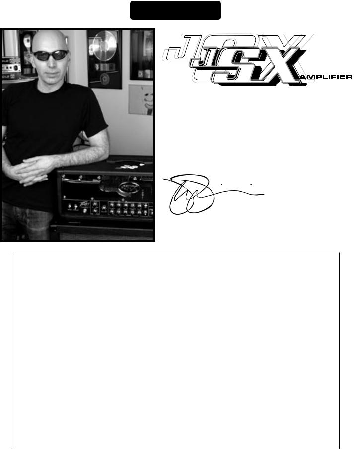
JSX™ Joe Satriani Signature All-Tube Amplifier
For more information on other great Peavey products, visit your local Peavey dealer or go online at www.peavey.com
Intended to alert the user to the presence of uninsulated “dangerous voltage” within the product’s enclosure that may be of sufficient magnitude to constitute a risk of electric shock to persons.
Intended to alert the user of the presence of important operating and maintenance (servicing) instructions in the literature accompanying the product.
CAUTION: Risk of electrical shock — DO NOT OPEN!
CAUTION: To reduce the risk of electric shock, do not remove cover. No user serviceable parts inside. Refer servicing to qualified service personnel.
WARNING: To prevent electrical shock or fire hazard, do not expose this appliance to rain or moisture. Before using this appliance, read the operating guide for further warnings.
Este símbolo tiene el propósito, de alertar al usuario de la presencia de “(voltaje) peligroso” sin aislamiento dentro de la caja del producto y que puede tener una magnitud suficiente como para constituir riesgo de descarga eléctrica.
Este símbolo tiene el propósito de alertar al usario de la presencia de Instrucciones importantes sobre la operación y mantenimiento en la información que viene con el producto.
PRECAUCION: Riesgo de descarga eléctrica ¡NO ABRIR!
PRECAUCION: Para disminuír el riesgo de descarga eléctrica, no abra la cubierta. No hay piezas útiles dentro. Deje todo mantenimiento en manos del personal técnico cualificado.
ADVERTENCIA: Para evitar descargas eléctricas o peligro de incendio, no deje expuesto a la lluvia o humedad este aparato Antes de usar este aparato, Iea más advertencias en la guía de operación.
Ce symbole est utilisé dans ce manuel pour indiquer à l’utilisateur la présence d’une tension dangereuse pouvant être d’amplitude suffisante pour constituer un risque de choc électrique.
Ce symbole est utilisé dans ce manuel pour indiquer à l’utilisateur qu’il ou qu’elle trouvera d’importantes instructions concernant l’utilisation et l’entretien de l’appareil dans le paragraphe signalé.
ATTENTION: Risques de choc électrique — NE PAS OUVRIR!
ATTENTION: Afin de réduire le risque de choc électrique, ne pas enlever le couvercle. Il ne se trouve à l’intérieur aucune pièce pouvant être reparée par l’utilisateur. Confiez I’entretien et la réparation de l’appareil à un réparateur Peavey agréé.
AVERTISSEMENT: Afin de prévenir les risques de décharge électrique ou de feu, n’exposez pas cet appareil à la pluie ou à l’humidité. Avant d’utiliser cet appareil, lisez attentivement les avertissements supplémentaires de ce manuel.
Dieses Symbol soll den Anwender vor unisolierten gefährlichen Spannungen innerhalb des Gehäuses warnen, die von Ausreichender Stärke sind, um einen elektrischen Schlag verursachen zu können.
Dieses Symbol soll den Benutzer auf wichtige Instruktionen in der Bedienungsanleitung aufmerksam machen, die Handhabung und Wartung des Produkts betreffen.
VORSICHT: Risiko — Elektrischer Schlag! Nicht öffnen!
VORSICHT: Um das Risiko eines elektrischen Schlages zu vermeiden, nicht die Abdeckung enfernen. Es befinden sich keine Teile darin, die vom Anwender repariert werden könnten. Reparaturen nur von qualifiziertem Fachpersonal durchführen lassen.
ACHTUNG: Um einen elektrischen Schlag oder Feuergefahr zu vermeiden, sollte dieses Gerät nicht dem Regen oder Feuchtigkeit ausgesetzt werden. Vor Inbetriebnahme unbedingt die Bedienungsanleitung lesen.
2

IMPORTANT SAFETY INSTRUCTIONS
WARNING: When using electrical products, basic cautions should always be followed, including the following:
1.Read these instructions.
2.Keep these instructions.
3.Heed all warnings.
4.Follow all instructions.
5.Do not use this apparatus near water.
6.Clean only with a dry cloth.
7.Do not block any of the ventilation openings. Install in accordance with manufacturer’s instructions.
8.Do not install near any heat sources such as radiators, heat registers, stoves or other apparatus (including amplifiers) that produce heat.
9.Do not defeat the safety purpose of the polarized or grounding-type plug. A polarized plug has two blades with one wider than the other. A grounding type plug has two blades and a third grounding plug. The wide blade or third prong is provided for your safety. If the provided plug does not fit into your outlet, consult an electrician for replacement of the obsolete outlet.
10.Protect the power cord from being walked on or pinched, particularly at plugs, convenience receptacles, and the point they exit from the apparatus.
11.Note for UK only: If the colors of the wires in the mains lead of this unit do not correspond with the terminals in your plug‚ proceed as follows:
a)The wire that is colored green and yellow must be connected to the terminal that is marked by the letter E‚ the earth symbol‚ colored green or colored green and yellow.
b)The wire that is colored blue must be connected to the terminal that is marked with the letter N or the color black.
c)The wire that is colored brown must be connected to the terminal that is marked with the letter L or the color red.
12.Only use attachments/accessories provided by the manufacturer.
13.Use only with a cart, stand, tripod, bracket, or table specified by the manufacturer, or sold with the apparatus. When
a cart is used, use caution when moving the cart/apparatus combination to avoid injury from tip-over.
14.Unplug this apparatus during lightning storms or when unused for long periods of time.
15.Refer all servicing to qualified service personnel. Servicing is required when the apparatus has been damaged in any way, such as power-supply cord or plug is damaged, liquid has been spilled or objects have fallen into the apparatus, the apparatus has been exposed to rain or moisture, does not operate normally, or has been dropped.
16.Never break off the ground pin. Write for our free booklet “Shock Hazard and Grounding.” Connect only to a power supply of the type marked on the unit adjacent to the power supply cord.
17.If this product is to be mounted in an equipment rack, rear support should be provided.
18.Exposure to extremely high noise levels may cause a permanent hearing loss. Individuals vary considerably in susceptibility to noise-induced hearing loss, but nearly everyone will lose some hearing if exposed to sufficiently intense noise for a sufficient time. The U.S. Government’s Occupational and Health Administration (OSHA) has specified the following permissible noise level exposures:
Duration Per Day In Hours |
Sound Level dBA, Slow Response |
8 |
90 |
6 |
92 |
4 |
95 |
3 |
97 |
2 |
100 |
1 1/2 |
102 |
1 |
105 |
1/2 |
110 |
1/4 or less |
115 |
According to OSHA, any exposure in excess of the above permissible limits could result in some hearing loss. Ear plugs or protectors to the ear canals or over the ears must be worn when operating this amplification system in order to prevent a permanent hearing loss, if exposure is in excess of the limits as set forth above. To ensure against potentially dangerous exposure to high sound pressure levels, it is recommended that all persons exposed to equipment capable of producing high sound pressure levels such as this amplification system be protected by hearing protectors while this unit is in operation.
SAVE THESE INSTRUCTIONS!
3
ENGLISH
™
Congratulations on purchasing a Peavey JSX guitar amplifier. The JSX is a guitar player’s dream come true, an amp that delivers superior sound quality and high performance for any style of guitar playing. Only the finest materials are used to create this great-sounding, rugged, tour-worthy and very unique-looking tone machine. I hope you like this amp as much as I do!
Joe Satriani
Features
•Three 12AX7 preamp tubes
•Four EL34 power amp tubes driven by a 12AX7
•Power amp convertible to use four 6L6GC tubes
•Footswitchable effects loop with independent send and return controls
•Resonance and presence damping controls
•Fully adjustable noise gate circuitry on Ultra and Crunch channels
•Line out with level control
•Cabinet impedance switch (4, 8 or 16 Ohms)
•Heavy duty power, standby and channel select toggle switches
•Classic power status indicator lamp
•Chrome-plated brass control knobs
4
FRONT PANEL
4 |
13 |
14 |
20 |
1 |
2 |
3 |
5 |
6 |
7 |
8 |
9 |
10 |
11 |
15 |
16 |
17 |
10 |
18 |
19 |
12
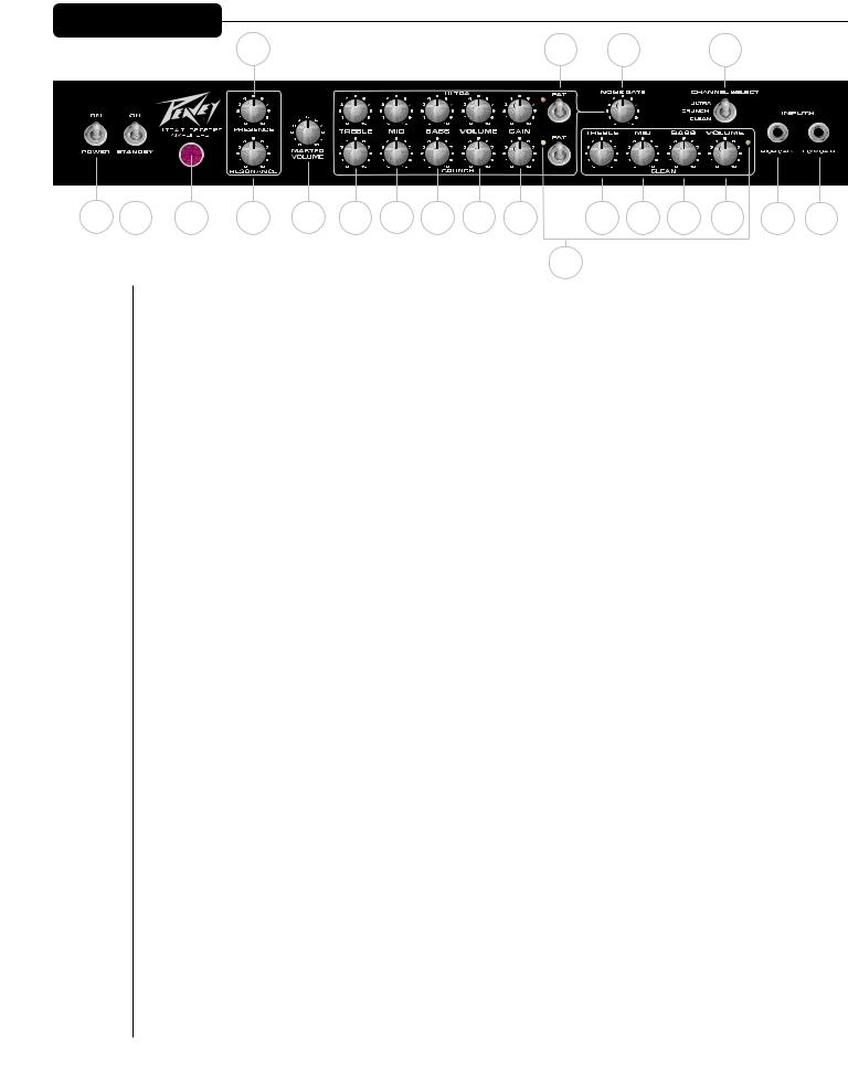
(1)POWER SWITCH
This two-way toggle switch applies mains power to the unit. The red POWER STATUS LAMP (3) will illuminate when this switch is in the ON position.
(2)STANDBY SWITCH
This two-way toggle switch allows the amp to be placed in STANDBY mode. In the STANDBY position the tubes stay hot but the amplifier is not operational. Switching to the ON position places the amp in active mode.
(3)POWER STATUS LAMP
This indicator illuminates when mains power is being supplied to the amp.
(4)PRESENCE
Used to fine-tune the high frequency range of the speaker enclosure by varying the damping factor of the amplifier at high frequencies.
(5)RESONANCE
Used to fine-tune the low frequency range of the speaker enclosure by varying the damping factor of the amplifier at low frequencies.
(6)MASTER VOLUME
This control sets the overall volume level of the amp. Once the desired balance between the three channels in the amplifier has been achieved, the entire output level of the unit can be increased or decreased by rotating this control. Clockwise rotation increases level; counterclockwise rotation decreases level.
(7)TREBLE
This control, on both the Ultra and Crunch channels, varies the high frequency response of the amplifier. It is an active control (shelving type) and allows ˜12 dB of boost or cut.
(8)MID
This control, on both the Ultra and Crunch channels, varies the mid frequency response of the amplifier. It is an active control (peak/notch type) and allows ˜12 dB of boost or cut.
5

(9)BASS
This control, on both the Ultra and Crunch channels, varies the low frequency response of the amplifier. It is an active control (shelving type) and allows ˜12 dB of boost or cut.
(10)VOLUME
This control, on all three channels, sets the overall level of its respective channel.
(11)GAIN
This control, on both the Ultra and Crunch channels, controls the input volume level of the channel. Rotating this control clockwise will increase the amount of preamp distortion and sustain.
(12)CHANNEL ACTIVATION LEDs
These indicators signify which channel is active. Ultra channel activation illuminates the red LED; Crunch channel activation illuminates the yellow LED; and Clean channel activation illuminates the green LED.
(13)FAT SWITCH
These two-position toggle switches on the Ultra and Crunch channels modify the low frequency responce of the amplifier and have the most noticeable effect when the guitar is "cleaned up," i.e. with the guitar's volume control turned down. This control affects the tightness of the attack of the notes; the attack is sloppier when the switch is in the "FAT" position.
(14)NOISE GATE
This control is shared by the Ultra and Crunch channels and adjusts the effectiveness of the noise gate circuitry. Noise is reduced more as the control is turned clockwise. Avoid using high settings of the noise gate when using lower gain settings, since at these settings the decay of the note will be adversely affected.
(15)TREBLE
This passive control regulates the high frequencies for the Clean channel.
(16)MID
This passive control regulates the mid frequencies for the Clean channel.
(17)BASS
This passive control regulates the low frequencies for the Clean channel.
(18)HIGH GAIN INPUT
Used for most electronic guitars. It is 6 dB louder than the Low Gain input.
(19)LOW GAIN INPUT
Provided for instruments that have etremely high outputs that tend to overdrive (distort) the High Gain input. If both inputs are used simultaneously, the output levels are the same (both are Low Gain).
(20)CHANNEL SELECT SWITCH
This three-position toggle switch allows selection between the amplifier’s three channels. LED (12) illumination indicates which channel is active. Channel switching can also be accomplished by footswitch. See the FOOTSWITCH section of this manual for explanation of switch operation. The CHANNEL SELECT SWITCH must be set in the Ultra position in order for the footswitch to operate properly.
6
REAR PANEL
31
22 |
24 |
26 |
|
28 |
30 |
|
21 |
23 |
25 |
27 |
29 |
32 |
33 |
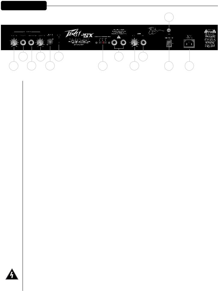
(21)EFFECTS SEND LEVEL
This calibrated (0 – 10) control sets the level of signal being sent to external effects and/or signal processors. Clockwise rotation increases the amount of signal being sent; counterclockwise rotation decreases the amount. For the quietest operation, the EFFECTS SEND LEVEL should be set as high as possible. Generally, the SEND and RETURN levels should be set oppositely. If the EFFECTS SEND LEVEL is set low, the EFFECTS RETURN LEVEL (24) is set high to achieve unity gain. If volume boost is desired, turn both controls to higher settings.
(22/23) EFFECTS SEND/EFFECTS RETURN
These 1/4" mono (TS) jacks allow signal to be sent to and returned from external effects and/or signal processors. Using shielded cables with 1/4" mono (TS) phone plugs, patch from EFFECTS SEND to the input of the external device and from the output of the external device to EFFECTS RETURN. Only
devices that do not increase signal gain should be used in this effects loop (chorus, delay, reverb, etc.). If the footswitch is used, the EFFECTS SELECTOR (37) switch must be depressed to activate the effects loop. See the FOOTSWITCH section of this manual for explanation of switch operation.
(24)EFFECTS RETURN LEVEL
This calibrated (0 – 10) control sets the level of signal being returned from external effects and/or signal processors. Clockwise rotation increases the amount of signal being returned; counterclockwise rotation decreases the amount. Again, SEND and RETURN levels should be set oppositely, with the SEND level being high and the RETURN level low to ensure the quietest operation.
(25)REMOTE SWITCH
This seven-pin DIN connector is provided for the connection of the remote footswitch. The footswitch cable should be connected before the amp is powered up. See the FOOTSWITCH section of this manual for an explanation of switch operation.
(26)BIAS TEST TERMINALS
These terminals are provided to measure the bias of the amplifier’s power tubes. A knob behind the back panel grill allows for adjustment. Bias adjustment should only be done by a qualified technician.
7

(27)CABINET IMPEDANCE SWITCH
This three-position switch allows appropriate selection of speaker cabinet impedance. If two enclosures of equal impedance are used, the switch should be set to half the individual value. For example, two 16 Ohm enclosures necessitate an 8 Ohm setting, while two 8 Ohm enclosures would require a 4 Ohm setting. Minimum speaker impedance is 4 Ohms.
(28)SPEAKER OUTPUTS
These paralleled 1/4" mono (TS) jacks are provided for the connection of speaker enclosure(s). Again, minimum speaker impedance is 4 Ohms. The CABINET IMPEDANCE SWITCH (27) should be set to match the load of the speaker cabinet(s).
(29)LINE OUT LEVEL
This control sets the level of signal being sent out of the LINE OUT (30) jack. It may be used to balance the level of slave power amp/speaker systems driven from the LINE OUT (30) to the level of cabinets driven from the SPEAKER OUTPUTS (28).
(30)LINE OUT
This 1/4" mono (TS) jack provides a post-power amp signal to drive another power amp/speaker system while maintaining the amplifier’s tone.
(31)FUSE
A fuse is located within the cap of the fuse holder. This fuse must be replaced with one of the same type and value to avoid damaging the amplifier and voiding the warranty. If the amp repeatedly blows the fuse, it should be taken to a qualified service center for repair.
WARNING: THE FUSE SHOULD ONLY BE REPLACED AFTER THE POWER CORD HAS BEEN DISCONNECTED.
(32)GROUND POLARITY SWITCH
This three-position, rocker-type switch should normally be placed in the center (0) position. If hum or noise is noticed coming from the speaker enclosure(s), the switch may be placed in the “+” or “-” position to minimize hum/noise. If changing the polarity does not alleviate the problem, consult your authorized Peavey dealer, the Peavey factory or a qualified service technician.
(33)IEC MAINS CONNECTOR
This is a standard IEC power connector. An AC mains cord having the appropriate AC plug and ratings for the intended operating voltage is included in the carton. The mains cord should be connected to the amplifier before connecting to a suitable AC outlet.
U.S DOMESTIC AC MAINS CORD
The mains cord supplied with the unit is a heavy duty, three-conductor type with a conventional 120 VAC plug with ground pin. If the outlet used does not have a ground pin, a suitable grounding adapter should be used and the third wire should be properly grounded.
Never break off the ground pin on any equipment. It is provided for your safety.
NOTE FOR UK ONLY:
If the colors of the wires in the mains lead of this unit do not correspond with the colored markings identifying the terminals in your plug, proceed as follows: (1) The wire that is colored green and yellow must be connected to the terminal that is marked by the letter E, the earth symbol or colored green or green and yellow; (2) The wire that is colored blue must be connected to the terminal that is marked with the letter N or the color black;
(3) The wire that is colored brown must be connected to the terminal that is marked with the letter L or the color red.
8
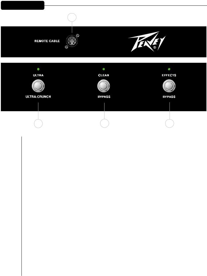
FOOTSWITCH
34
35 |
36 |
37 |
(34)CABLE CONNECTOR
This seven-pin DIN connector is provided for connecting the footswitch to the amplifier REMOTE SWITCH (25) via the cable included in the carton. Connections at the switch and the amplifier should be made before the amp is powered up.
(35)ULTRA/CRUNCH SELECTOR
This switch selects between the Ultra and Crunch channels on the amplifier. The adjacent LED will illuminate when the Ultra channel is selected. When the LED is dark, the Crunch channel is selected. The CLEAN SELECTOR (36) must be in the BYPASS mode to activate either the Ultra or Crunch channel.
(36)CLEAN SELECTOR
This switch selects the Clean channel and will activate regardless of the position of the ULTRA/CRUNCH SELECTOR (35). The adjacent LED will illuminate when the Clean channel is selected. This switch must be in the BYPASS position, indicated by a dark LED, in order to utilize the ULTRA/CRUNCH SELECTOR (35).
(37)EFFECTS SELECTOR
This switch activates the amplifier’s effects loop (21 – 24). The adjacent LED will illuminate when the effects loop is active.
9
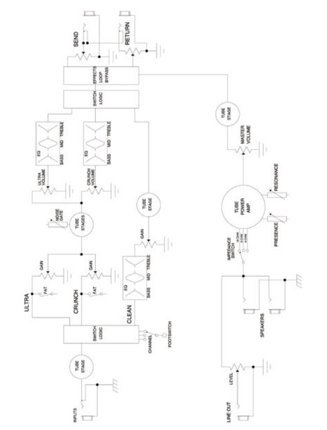
JSX™ Block Diagram
10
JSX™
SPECIFICATIONS
POWER AMPLIFIER SECTION:
Tubes:
Four EL34 tubes with 12AX7 driver
Rated Power & Load:
120 Watts RMS into 16, 8 or 4 Ohms
Power @ Clipping:
(typically @ 5% THD, 1 kHz, 120 VAC line) 120 Watts RMS into 16, 8 or 4 Ohms
Frequency Response:
+/-3 dB, 50 Hz to 20 kHz @ 90 Watts RMS into 8 Ohms
Hum & Noise:
Greater than 76 dB below rated power
Power Consumption:
Domestic: 400 Watts, 50/60 Hz, 120 V AC Export: 400 Watts, 60 Hz, 220-230/240 V AC
PREAMP SECTION:
Tubes:
Three 12AX7 tubes
Thefollowingspecsaremeasured@1kHz withthecontrolspresetasfollows:
All EQ controls @ 5
Ultra & Crunch Volumes @ 10 Master Volume @ 5
Resonance and Presence controls @ 5 Effects Send @ 0
Effects Return @ 10
Nominal levels are with Gain @ 5 Minimum levels are with Gain @ 10 All levels increased by 6 dB if using Low Gain input
Clean Channel:
Nominal Input Level: -10 dBV, 300 mV RMS Minimum Input Level: -22 dBV, 80 mV RMS Maximum Input Level: 0 dBV, 1 .0 mV RMS
Crunch Channel:
Nominal Input Level: -60 dBV, 1 mV RMS
Minimum Input Level: -90 dBV, 0.03 mV RMS
Ultra Channel:
Nominal Input Level: -70 dBV, 0.3 mV RMS
Minimum Input Level: -90 dBV, 0.03 mV RMS
Effects Send:
Load Impedance: 47 k Ohms or greater Minimum Output:
-10 dBV, 300 mV RMS Maximum Output:
0 dBV, 1 V RMS
Effects Return:
Impedance: High Z, 80 k Ohms
Minimum Input Sensitivity:
-10 dBV, 300 mV RMS
Maximum Input Sensitivity:
0 dBV, 1 V RMS
Line Output:
Load Impedance: 47 k Ohms or greater Adjustable Output:
+/- 20 dBV, 0.1V RMS-10 V RMS
Note: For proper ventilation‚ allow 24" clearance from nearest combustible surface.
Remote Footswitch:
Special three-button metal footswitch with LED indicators and detachable cord (supplied) selects between three channels and bypasses effects loop
System Hum & Noise @ Nominal Level:
(Clean channel - 20 Hz to 20 kHz unweighted) Greater than 74 dB below rated power (AdjustablenoisegatecircuitryforUltra&Crunch)
Equalization:
Custom bass, mid & treble passive-type EQ on Clean channel
Separate active +/-12 dB bass, mid & treble EQs on Ultra & Crunch channels
Fat switches on Ultra & Crunch modifies low frequency response
Resonance and presence damping EQ controls in power amp
Dimensions & Weight:
11" (279 mm) H x 26.5" (673 mm) W x 11" (279 mm) D
52 lbs.(23.6 kG)
11
 Loading...