


 Loading...
RocketLink-G Model 3088 Series
G.SHDSL NTU with fixed serial interface
User Manual
Important
This is a Class A device and is not intended nor approved for use in a residential environment.
Sales Office: +1 (301) 975-1000
Technical Support: +1 (301) 975-1007
E-mail: support@patton.com
WWW: www.patton.com
Part Number: 07M3088-GSG, Rev. J
Revised: February 15, 2012
Patton Electronics Company, Inc.
7622 Rickenbacker Drive
Gaithersburg, MD 20879 USA
Tel: +1 (301) 975-1000
Fax: +1 (301) 869-9293
Support: +1 (301) 975-1007 Web: www.patton.com E-mail: support@patton.com
Trademark Statement
The term RocketLink-G is a trademark of Patton Electronics Company. All other trademarks presented in this document are the property of their respective owners.
Copyright © 2012, Patton Electronics Company. All rights reserved.
The information in this document is subject to change without notice. Patton Electronics assumes no liability for errors that may appear in this document.
Warranty Information
Patton Electronics warrants all Model 3088 components to be free from defects, and will—at our option—repair or replace the product should it fail within one year from the first date of shipment.
This warranty is limited to defects in workmanship or materials, and does not cover customer damage, abuse or unauthorized modification. If this product fails or does not perform as warranted, your sole recourse shall be repair or replacement as described above. Under no condition shall Patton Electronics be liable for any damages incurred by the use of this product. These damages include, but are not limited to, the following: lost profits, lost savings and incidental or consequential damages arising from the use of or inability to use this product. Patton Electronics specifically disclaims all other warranties, expressed or implied, and the installation or use of this product shall be deemed an acceptance of these terms by the user.
Note Conformity documents of all Patton products can be viewed online at www.patton.com under the appropriate product page.

Summary Table of Contents |
|
|
1 |
General information ...................................................................................................................................... |
14 |
2 |
Configuration................................................................................................................................................ |
18 |
3 |
RocketLink-G installation ............................................................................................................................. |
41 |
4 |
Operation ...................................................................................................................................................... |
51 |
5 |
Remote console operation ............................................................................................................................. |
55 |
6 |
Software Upgrade .......................................................................................................................................... |
60 |
7 |
Reset configuration to factory defaults .......................................................................................................... |
62 |
8 |
Contacting Patton for assistance ................................................................................................................... |
64 |
A |
Compliance information .............................................................................................................................. |
67 |
B |
Specifications ................................................................................................................................................ |
71 |
C |
Factory default values ................................................................................................................................... |
75 |
D |
Factory replacement parts and accessories .................................................................................................... |
78 |
E |
Interface pinouts .......................................................................................................................................... |
80 |
3

Table of Contents |
|
|
|
Summary Table of Contents ........................................................................................................................... |
3 |
|
Table of Contents ........................................................................................................................................... |
4 |
|
List of Figures ................................................................................................................................................. |
8 |
|
List of Tables .................................................................................................................................................. |
9 |
|
About this guide ........................................................................................................................................... |
10 |
|
Audience............................................................................................................................................................... |
10 |
|
Structure............................................................................................................................................................... |
10 |
|
Precautions ........................................................................................................................................................... |
11 |
|
Safety when working with electricity ............................................................................................................... |
12 |
|
....................................................................................................................................................................... |
13 |
|
General observations ....................................................................................................................................... |
13 |
|
Typographical conventions used in this document................................................................................................ |
13 |
|
General conventions ....................................................................................................................................... |
13 |
1 |
General information ...................................................................................................................................... |
14 |
|
RocketLink-G 3088 overview................................................................................................................................ |
15 |
|
Serial interface types .............................................................................................................................................. |
15 |
|
Features ................................................................................................................................................................. |
15 |
|
Power input connector .......................................................................................................................................... |
16 |
|
External AC universal power supply ................................................................................................................ |
16 |
|
External 48 VDC power supply ...................................................................................................................... |
17 |
2 |
Configuration................................................................................................................................................ |
18 |
|
Introduction .......................................................................................................................................................... |
19 |
|
Software (CLI) configuration .......................................................................................................................... |
19 |
|
Hardware (DIP-switch) configuration ............................................................................................................. |
19 |
|
Configuring the DIP switches ......................................................................................................................... |
22 |
|
System reset mode ........................................................................................................................................... |
23 |
|
Software upgrades ..................................................................................................................................... |
23 |
|
Configuration reset to factory defaults ....................................................................................................... |
23 |
|
DIP switch settings ......................................................................................................................................... |
23 |
|
DIP switch settings for RocketLink-G models 3088/CA and 3088/D ............................................................. |
24 |
|
S1-1 through S1-7: Data Rate (RocketLink-G models 3088/CA and 3088/D) ......................................... |
25 |
|
S1-8: TX Clock (RocketLink-G models 3088/CA and 3088/D) ............................................................... |
27 |
|
S2-2: Line Probe (Models 3088/CA and D) .............................................................................................. |
27 |
|
S2-3: Annex A/B (Models 3088/CA and D) .............................................................................................. |
27 |
|
S2-4 through S2-5: Clock Mode (Models 3088/CA and D) ...................................................................... |
27 |
|
X.21 operation. ................................................................................................................................... |
28 |
|
S2-6: DTE Loops (RocketLink-G models 3088/CA only) ........................................................................ |
28 |
|
DIP switch settings for RocketLink-G models 3088/K and 3088/T ................................................................ |
29 |
|
S1-1 through S1-6: TimeSlots & Data Rate (RocketLink-G Models 3088/K and 3088/T) ....................... |
30 |
|
S1-7 and S1-8: Line Build Out (Models 3088/K and 3088/T) .................................................................. |
31 |
4

Model 3088 Series User Manual |
Table of Contents |
|
|
|
S2-2 Line Code (Models 3088/K and 3088/T) ......................................................................................... |
31 |
|
S2-3: Annex A/B (Models 3088/K and 3088/T) ....................................................................................... |
31 |
|
S2-4 through S2-5: Clock Mode (Models 3088/K and 3088/T)) .............................................................. |
31 |
|
S2-6 through S2-8: Line Type (Models 3088/K and 3088/T) ................................................................... |
32 |
|
Console ........................................................................................................................................................... |
32 |
|
Help Commands ....................................................................................................................................... |
35 |
|
System Configuration Commands ............................................................................................................ |
36 |
|
System Status Commands ......................................................................................................................... |
36 |
|
DSL Configuration Commands ................................................................................................................ |
36 |
|
DSL Status Command .............................................................................................................................. |
37 |
|
DSL Clear Errcntrs Command .................................................................................................................. |
37 |
|
T1/E1 Configuration Commands ............................................................................................................. |
37 |
|
T1/E1 Status Commands .......................................................................................................................... |
38 |
|
Remote Console .............................................................................................................................................. |
38 |
|
Example Command Line Interface Session ................................................................................................ |
38 |
|
RocketLink Plug ‘n’ Play ................................................................................................................................. |
39 |
3 |
RocketLink-G installation ............................................................................................................................. |
41 |
|
Installation ............................................................................................................................................................ |
42 |
|
Connecting the twisted pair interface .............................................................................................................. |
42 |
|
Connecting the Model 3088/CA (V.35) serial interface .................................................................................. |
43 |
|
Connecting the Model 3088/CA (V.35) to a “DTE” device ...................................................................... |
43 |
|
Connecting the Model 3088/CA (V.35) to a “DCE” device ...................................................................... |
43 |
|
Connecting the Model 3088/D (X.21) serial interface .................................................................................... |
44 |
|
Connecting the Model 3088/D (X.21) to a “DCE” or “DTE” device ....................................................... |
44 |
|
Opening the Case ...................................................................................................................................... |
45 |
|
Connecting the Model 3088/K serial interface ................................................................................................ |
46 |
|
Connecting the Model 3088/K to an E1 Network .................................................................................... |
46 |
|
Connect twisted pair (120 ohm) to E1 network .............................................................................................. |
47 |
|
Connecting dual coaxial cable (75 ohm) to E1 network .................................................................................. |
47 |
|
Connecting the Model 3088/T (T1) serial interface ........................................................................................ |
48 |
|
Connect Twisted Pair (100 ohm) to T1 Network ..................................................................................... |
48 |
|
Connecting power ........................................................................................................................................... |
49 |
|
External AC universal power supply .......................................................................................................... |
49 |
|
DC Power ................................................................................................................................................. |
50 |
4 |
Operation ...................................................................................................................................................... |
51 |
|
Introduction .......................................................................................................................................................... |
52 |
|
Power-up ........................................................................................................................................................ |
52 |
|
LED status monitors ....................................................................................................................................... |
52 |
|
Power (Green) ........................................................................................................................................... |
52 |
|
DSL (Green) ............................................................................................................................................. |
52 |
|
Link (Green) (Models K and T only) ........................................................................................................ |
52 |
|
Term (Green) [Models C and D] .............................................................................................................. |
53 |
|
TM/ER (Red) ........................................................................................................................................... |
53 |
5

Model 3088 Series User Manual |
Table of Contents |
|
|
|
LOS (Red) [Models K and T] ................................................................................................................... |
53 |
|
Test modes ...................................................................................................................................................... |
53 |
|
Loopbacks ................................................................................................................................................. |
54 |
|
Patterns ..................................................................................................................................................... |
54 |
5 |
Remote console operation ............................................................................................................................. |
55 |
|
Introduction .......................................................................................................................................................... |
56 |
|
Establishing a Remote Console Session ........................................................................................................... |
56 |
|
How to Connect ....................................................................................................................................... |
56 |
|
How to Disconnect ................................................................................................................................... |
57 |
|
Differences in Local and Remote Control Session Behavior ...................................................................... |
58 |
6 |
Software Upgrade .......................................................................................................................................... |
60 |
|
Introduction .......................................................................................................................................................... |
61 |
7 Reset configuration to factory defaults.......................................................................................................... |
62 |
|
|
Introduction .......................................................................................................................................................... |
63 |
8 Contacting Patton for assistance ................................................................................................................... |
64 |
|
|
Introduction .......................................................................................................................................................... |
65 |
|
Contact information.............................................................................................................................................. |
65 |
|
Patton support headquarters in the USA ......................................................................................................... |
65 |
|
Alternate Patton support for Europe, Middle East, and Africa (EMEA) .......................................................... |
65 |
|
Warranty Service and Returned Merchandise Authorizations (RMAs)................................................................... |
65 |
|
Warranty coverage .......................................................................................................................................... |
65 |
|
Out-of-warranty service ............................................................................................................................. |
66 |
|
Returns for credit ...................................................................................................................................... |
66 |
|
Return for credit policy ............................................................................................................................. |
66 |
|
RMA numbers ................................................................................................................................................ |
66 |
|
Shipping instructions ................................................................................................................................ |
66 |
A |
Compliance information .............................................................................................................................. |
67 |
|
Compliance ........................................................................................................................................................... |
68 |
|
EMC ............................................................................................................................................................... |
68 |
|
Safety .............................................................................................................................................................. |
68 |
|
PSTN Regulatory ............................................................................................................................................ |
68 |
|
FCC Part 68 (ACTA) Statement ........................................................................................................................... |
68 |
|
Radio and TV Interference (FCC Part 15) ............................................................................................................ |
69 |
|
Industry Canada Notice ........................................................................................................................................ |
69 |
|
CE Declaration of Conformity .............................................................................................................................. |
69 |
|
Authorized European Representative ..................................................................................................................... |
70 |
B |
Specifications ................................................................................................................................................ |
71 |
|
Clocking modes..................................................................................................................................................... |
72 |
|
DTE rate ............................................................................................................................................................... |
72 |
|
Serial interface ....................................................................................................................................................... |
72 |
|
Serial connector ..................................................................................................................................................... |
72 |
|
Diagnostics............................................................................................................................................................ |
72 |
6

Model 3088 Series User Manual |
Table of Contents |
|
|
|
Status LEDs........................................................................................................................................................... |
72 |
|
Power (Green) ........................................................................................................................................... |
72 |
|
DSL (Green) ............................................................................................................................................. |
72 |
|
Link (Green) (T1/E1 only) ....................................................................................................................... |
72 |
|
Term (Green) ............................................................................................................................................ |
73 |
|
TM/ER (Red) ........................................................................................................................................... |
73 |
|
Configuration........................................................................................................................................................ |
73 |
|
Power and power supply specifications .................................................................................................................. |
73 |
|
External AC universal power supply ................................................................................................................ |
73 |
|
External 48 VDC power supply ...................................................................................................................... |
74 |
|
Transmission line .................................................................................................................................................. |
74 |
|
Line coding ........................................................................................................................................................... |
74 |
|
Line rates (DSL line) ............................................................................................................................................. |
74 |
|
Line interface......................................................................................................................................................... |
74 |
|
G.SHDSL physical connection.............................................................................................................................. |
74 |
|
Environment ......................................................................................................................................................... |
74 |
C |
Factory default values ................................................................................................................................... |
75 |
|
Factory default values for software-configurable parameters................................................................................... |
76 |
D Factory replacement parts and accessories .................................................................................................... |
78 |
|
|
Factory replacement parts and accessories .............................................................................................................. |
79 |
E |
Interface pinouts .......................................................................................................................................... |
80 |
|
RJ-11 non-shielded DSL port................................................................................................................................ |
81 |
|
V.35 interface ........................................................................................................................................................ |
81 |
|
T1/E1 interface ..................................................................................................................................................... |
81 |
|
X.21 interface ........................................................................................................................................................ |
82 |
|
RS-232 console interface pin assignments.............................................................................................................. |
82 |
7

List of Figures
1 |
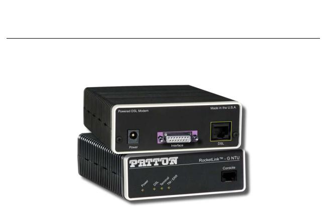
RocketLink-G 3088 . . . . . . . . . . . . . . . . . . . . . . . . . . . . . . . . . . . . . . . . . . . . . . . . . . . . . . . . . . . . . . . . . . . . . |
15 |
2 |
Power connection barrel receptacle 5 VDC diagram . . . . . . . . . . . . . . . . . . . . . . . . . . . . . . . . . . . . . . . . . . . . . |
16 |
3 |
RocketLink-G (Model 3088/D shown) . . . . . . . . . . . . . . . . . . . . . . . . . . . . . . . . . . . . . . . . . . . . . . . . . . . . . . |
19 |
4 |
Underside of Model 3088 showing location of DIP switches . . . . . . . . . . . . . . . . . . . . . . . . . . . . . . . . . . . . . . |
22 |
5 |
Close-up of configuration switches (all sets are identical appearance) . . . . . . . . . . . . . . . . . . . . . . . . . . . . . . . . |
23 |
6 |
Typical RocketLink Plug ‘n’ Play Application . . . . . . . . . . . . . . . . . . . . . . . . . . . . . . . . . . . . . . . . . . . . . . . . . . |
40 |
7 |
Model 3088 V.35/X.21 interfaces . . . . . . . . . . . . . . . . . . . . . . . . . . . . . . . . . . . . . . . . . . . . . . . . . . . . . . . . . . . |
42 |
8 |
Connecting the Model 3088/CA to V.35 Serial DTE . . . . . . . . . . . . . . . . . . . . . . . . . . . . . . . . . . . . . . . . . . . . |
43 |
9 |
Connecting the Model 3088/CA to V.35 Serial DCE . . . . . . . . . . . . . . . . . . . . . . . . . . . . . . . . . . . . . . . . . . . . |
44 |
10 |
Connecting the Model 3088/D to X.21 DTE or DCE . . . . . . . . . . . . . . . . . . . . . . . . . . . . . . . . . . . . . . . . . . . |
45 |
11 |
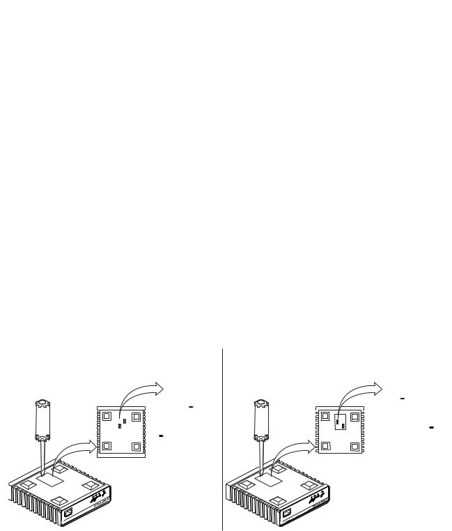
Opening the 3088 case with a small screwdriver . . . . . . . . . . . . . . . . . . . . . . . . . . . . . . . . . . . . . . . . . . . . . . . . |
45 |
12 |
Setting the DCE/DTE Strap (X.21 only) . . . . . . . . . . . . . . . . . . . . . . . . . . . . . . . . . . . . . . . . . . . . . . . . . . . . . |
46 |
13 |
120 Ohm RJ-48C E1 interface . . . . . . . . . . . . . . . . . . . . . . . . . . . . . . . . . . . . . . . . . . . . . . . . . . . . . . . . . . . . . |
47 |
14 |
RJ-45 cable diagram for E1 connection . . . . . . . . . . . . . . . . . . . . . . . . . . . . . . . . . . . . . . . . . . . . . . . . . . . . . . |
47 |
15 |
Model 3088/K rear panel . . . . . . . . . . . . . . . . . . . . . . . . . . . . . . . . . . . . . . . . . . . . . . . . . . . . . . . . . . . . . . . . . |
48 |
16 |
120 Ohm RJ-48C T1 interface . . . . . . . . . . . . . . . . . . . . . . . . . . . . . . . . . . . . . . . . . . . . . . . . . . . . . . . . . . . . . |
48 |
17 |
RJ-45 cable diagram for T1 connection . . . . . . . . . . . . . . . . . . . . . . . . . . . . . . . . . . . . . . . . . . . . . . . . . . . . . . |
49 |
18 |
DC Power Supply . . . . . . . . . . . . . . . . . . . . . . . . . . . . . . . . . . . . . . . . . . . . . . . . . . . . . . . . . . . . . . . . . . . . . . . |
50 |
19 |
Model 3088/CA front panel . . . . . . . . . . . . . . . . . . . . . . . . . . . . . . . . . . . . . . . . . . . . . . . . . . . . . . . . . . . . . . . |
52 |
20 |
3088/S Model Front Panel . . . . . . . . . . . . . . . . . . . . . . . . . . . . . . . . . . . . . . . . . . . . . . . . . . . . . . . . . . . . . . . . |
53 |
21 |
Model 3088 Block Diagram . . . . . . . . . . . . . . . . . . . . . . . . . . . . . . . . . . . . . . . . . . . . . . . . . . . . . . . . . . . . . . . |
53 |
22 |
Local Analog Loopback diagram . . . . . . . . . . . . . . . . . . . . . . . . . . . . . . . . . . . . . . . . . . . . . . . . . . . . . . . . . . . . |
54 |
23 |
Remote Digital Loopback diagram . . . . . . . . . . . . . . . . . . . . . . . . . . . . . . . . . . . . . . . . . . . . . . . . . . . . . . . . . . |
54 |
24 |
Remote control session diagram . . . . . . . . . . . . . . . . . . . . . . . . . . . . . . . . . . . . . . . . . . . . . . . . . . . . . . . . . . . . |
56 |
25 |
Opening a typical remote console session . . . . . . . . . . . . . . . . . . . . . . . . . . . . . . . . . . . . . . . . . . . . . . . . . . . . . |
57 |
26 |
Remote control session with LAL diagram . . . . . . . . . . . . . . . . . . . . . . . . . . . . . . . . . . . . . . . . . . . . . . . . . . . . |
58 |
27 |
Power connection barrel receptacle 5 VDC diagram . . . . . . . . . . . . . . . . . . . . . . . . . . . . . . . . . . . . . . . . . . . . . |
73 |
8

List of Tables
1 |
General conventions . . . . . . . . . . . . . . . . . . . . . . . . . . . . . . . . . . . . . . . . . . . . . . . . . . . . . . . . . . . . . . . . . . . . . |
13 |
2 |
RocketLink-G configurable parameters . . . . . . . . . . . . . . . . . . . . . . . . . . . . . . . . . . . . . . . . . . . . . . . . . . . . . . . |
20 |
3 |
Model 3088/CA and 3088/D - S1 DIP-Switch Functions . . . . . . . . . . . . . . . . . . . . . . . . . . . . . . . . . . . . . . . . |
24 |
4 |
Model 3088/CA and 3088/D - S2 DIP-Switch Functions . . . . . . . . . . . . . . . . . . . . . . . . . . . . . . . . . . . . . . . . |
24 |
5 |
S1-1 through S1-7 Data Rate DIP switch settings . . . . . . . . . . . . . . . . . . . . . . . . . . . . . . . . . . . . . . . . . . . . . . . |
25 |
6 |
S1-8 TX Clock DIP switch settings . . . . . . . . . . . . . . . . . . . . . . . . . . . . . . . . . . . . . . . . . . . . . . . . . . . . . . . . . |
27 |
7 |
S2-2 Line Probe Switch Settings . . . . . . . . . . . . . . . . . . . . . . . . . . . . . . . . . . . . . . . . . . . . . . . . . . . . . . . . . . . . |
27 |
8 |
S2-3 Annex Type settings . . . . . . . . . . . . . . . . . . . . . . . . . . . . . . . . . . . . . . . . . . . . . . . . . . . . . . . . . . . . . . . . . |
27 |
9 |
S2-4 and S2-5 Clock Mode Settings . . . . . . . . . . . . . . . . . . . . . . . . . . . . . . . . . . . . . . . . . . . . . . . . . . . . . . . . . |
27 |
10 |
X.21 Clocking . . . . . . . . . . . . . . . . . . . . . . . . . . . . . . . . . . . . . . . . . . . . . . . . . . . . . . . . . . . . . . . . . . . . . . . . . |
28 |
11 |
S2-6 V.35 Loopback settings . . . . . . . . . . . . . . . . . . . . . . . . . . . . . . . . . . . . . . . . . . . . . . . . . . . . . . . . . . . . . . |
28 |
12 |
Model 3088/K and 3088/T S1 DIP-Switch Functions . . . . . . . . . . . . . . . . . . . . . . . . . . . . . . . . . . . . . . . . . . . |
29 |
13 |
Model 3088/K and 3088/T S2 DIP-Switch Functions . . . . . . . . . . . . . . . . . . . . . . . . . . . . . . . . . . . . . . . . . . . |
29 |
14 |
S1-1 through S1-6 Timeslots & DSL Data Rate DIP switch settings . . . . . . . . . . . . . . . . . . . . . . . . . . . . . . . . |
30 |
15 |
S1-7 – S1-8: Line Build Out Settings . . . . . . . . . . . . . . . . . . . . . . . . . . . . . . . . . . . . . . . . . . . . . . . . . . . . . . . . |
31 |
16 |
S2-2 Line Code Switch Settings . . . . . . . . . . . . . . . . . . . . . . . . . . . . . . . . . . . . . . . . . . . . . . . . . . . . . . . . . . . . |
31 |
17 |
S2-3 Annex Type settings . . . . . . . . . . . . . . . . . . . . . . . . . . . . . . . . . . . . . . . . . . . . . . . . . . . . . . . . . . . . . . . . . |
31 |
18 |
S2-4 and S2-5 Clock Mode Settings . . . . . . . . . . . . . . . . . . . . . . . . . . . . . . . . . . . . . . . . . . . . . . . . . . . . . . . . . |
31 |
19 |
S2-6 through S2-8 Line Type Settings . . . . . . . . . . . . . . . . . . . . . . . . . . . . . . . . . . . . . . . . . . . . . . . . . . . . . . . |
32 |
20 |
3088/CA and 3088/D . . . . . . . . . . . . . . . . . . . . . . . . . . . . . . . . . . . . . . . . . . . . . . . . . . . . . . . . . . . . . . . . . . . |
76 |
21 |
3088/K . . . . . . . . . . . . . . . . . . . . . . . . . . . . . . . . . . . . . . . . . . . . . . . . . . . . . . . . . . . . . . . . . . . . . . . . . . . . . . . |
76 |
22 |
3088/T . . . . . . . . . . . . . . . . . . . . . . . . . . . . . . . . . . . . . . . . . . . . . . . . . . . . . . . . . . . . . . . . . . . . . . . . . . . . . . . |
77 |
9

About this guide
This guide describes installing and operating the Patton Electronics Model 3088 G.SHDSL RocketLink-G™ NTU.
Audience
This guide is intended for the following users:
•Operators
•Installers
•Maintenance technicians
Structure
This guide contains the following chapters and appendices:
•Chapter 1 on page 14 provides information about NTU features and capabilities
•Chapter 2 on page 18 contains an overview describing NTU operation and applications
•Chapter 3 on page 41 provides hardware installation procedures
•Chapter 4 on page 51 provides quick-start procedures for configuring the RocketLink-G NTU
•Chapter 5 on page 55 describes how to install and operate the RocketLink-G NTU
•Chapter 6 on page 60 describes how to configure the RocketLink-G NTU, save the configuration, reset the NTU to the factory default condition, and upgrade the system software
•Chapter 7 on page 62 describes the system tools that can be used to diagnose problems with the NTU
•Chapter 8 on page 64 contains information on contacting Patton technical support for assistance
•Appendix A on page 67 contains compliance information for the RocketLink-G NTU
•Appendix B on page 71 contains specifications for the NTU
•Appendix D on page 78 provides cable recommendations
•Appendix E on page 80 describes the NTU’s ports and pin-outs
For best results, read the contents of this guide before you install the NTU.
10
Model 3088 Series User Manual
Precautions
Notes, cautions, and warnings, which have the following meanings, are used throughout this guide to help you become aware of potential problems. Warnings are intended to prevent safety hazards that could result in personal injury. Cautions are intended to prevent situations that could result in property damage or
impaired functioning.
Note A note presents additional information or interesting sidelights.
The shock hazard symbol and WARNING heading indicate a potential electric shock hazard. Strictly follow the warning instructions to avoid injury caused
by electric shock.
WARNING
The alert symbol and WARNING heading indicate a potential safety hazard.
Strictly follow the warning instructions to avoid personal injury.
WARNING
The shock hazard symbol and CAUTION heading indicate a potential electric shock hazard. Strictly follow the instructions to
avoid property damage caused by electric shock.
CAUTION
The alert symbol and CAUTION heading indicate a potential hazard. Strictly follow the instructions to avoid property damage.
CAUTION
11
Model 3088 Series User Manual
Safety when working with electricity
•Do not open the device when the power cord is connected. For systems without a power switch and without an external power adapter, line voltages are present within the device when the power cord is connected.
WARNING
•For devices with an external power adapter, the power adapter shall be a listed imited Power Source The mains outlet that is utilized to power the device shall be within 10 feet (3 meters) of the device, shall be easily accessible, and protected by a circuit breaker in compliance with local regulatory requirements.
•For AC powered devices, ensure that the power cable used meets all applicable standards for the country in which it is to be installed.
•For AC powered devices which have 3 conductor power plugs (L1, L2 & GND or Hot, Neutral & Safety/Protective Ground), the wall outlet (or socket) must have an earth ground.
•For DC powered devices, ensure that the interconnecting cables are rated for proper voltage, current, anticipated temperature, flammability, and mechanical serviceability.
•WAN, LAN & PSTN ports (connections) may have hazardous voltages present regardless of whether the device is powered ON or OFF. PSTN relates to interfaces such as telephone lines, FXS, FXO, DSL, xDSL, T1, E1, ISDN, Voice, etc. These are known as “hazardous network voltages” and to avoid electric shock use caution when working near these ports. When disconnecting cables for these ports, detach the far end connection first.
•Do not work on the device or connect or disconnect cables during periods of lightning activity.
This device contains no user serviceable parts. This device can only be repaired by qualified service personnel.
WARNING
This device is NOT intended nor approved for connection to the PSTN. It is intended only for connection to customer premise equipment.
WARNING
In accordance with the requirements of council directive 2002/ 96/EC on Waste of Electrical and Electronic Equipment (WEEE), ensure that at end-of-life you separate this product from other waste and scrap and deliver to the WEEE collection system in your country for recycling.
12
Model 3088 Series User Manual
Electrostatic Discharge (ESD) can damage equipment and impair electrical circuitry. It occurs when electronic printed circuit cards are improperly handled and can result in complete or intermittent
CAUTION failures. Do the following to prevent ESD:
•Always follow ESD prevention procedures when removing and replacing cards.
•Wear an ESD-preventive wrist strap, ensuring that it makes good skin contact. Connect the clip to an unpainted surface of the chassis frame to safely channel unwanted ESD voltages to ground.
•To properly guard against ESD damage and shocks, the wrist strap and cord must operate effectively. If no wrist strap is available, ground yourself by touching the metal part of the chassis.
General observations
•Clean the case with a soft slightly moist anti-static cloth
•Place the unit on a flat surface and ensure free air circulation
•Avoid exposing the unit to direct sunlight and other heat sources
•Protect the unit from moisture, vapors, and corrosive liquids
Typographical conventions used in this document
This section describes the typographical conventions and terms used in this guide.
General conventions
The procedures described in this manual use the following text conventions:
|
|
Table 1. General conventions |
|
|
|
|
|
Convention |
|
|
Meaning |
|
|
|
|
Garamond blue type |
Indicates a cross-reference hyperlink that points to a figure, graphic, table, or sec- |
||
|
tion heading. Clicking on the hyperlink jumps you to the reference. When you |
||
|
have finished reviewing the reference, click on the Go to Previous View |
||
|
button |
|
in the Adobe® Acrobat® Reader toolbar to return to your starting point. |
|
|
||
|
|
|
|
Futura bold type |
Commands and keywords are in boldface font. |
||
|
|
|
|
Futura bold-italic type |
Parts of commands, which are related to elements already named by the user, are |
||
|
in boldface italic font. |
||
Italicized Futura type |
Variables for which you supply values are in italic font |
||
|
|
|
|
Futura type |
Indicates the names of fields or windows. |
||
Garamond bold type |
Indicates the names of command buttons that execute an action. |
||
|
|
|
|
13

Chapter 1 General information |
|
Chapter contents |
|
RocketLink-G 3088 overview................................................................................................................................ |
15 |
Serial interface types .............................................................................................................................................. |
15 |
Features ................................................................................................................................................................. |
15 |
Power input connector .......................................................................................................................................... |
16 |
External AC universal power supply ................................................................................................................ |
16 |
External 48 VDC power supply ...................................................................................................................... |
17 |
14
Model 3088 Series User Manual |
1 • General information |
|
|
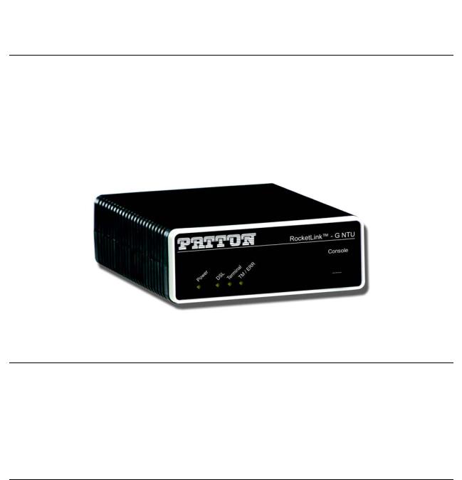
RocketLink-G 3088 overview
The Patton Electronics Model 3088 G.SHDSL RocketLink provides high speed 2-wire connectivity to ISPs, PTTs, and enterprise environments using Symmetrical High-data-rate Digital Subscriber Line
(G.SHDSL) technology.
As a symmetric DSL NTU, RocketLink DSL offers the same data rates in both directions over a single pair of regular twisted pair lines using TC-PAM modulation. Line connection is made with an RJ-45 jack. Standard versions of Model 3088 are powered by an 100/230 VAC (Universal) supply. The NTU features externallyaccessible DIP switches, loopback diagnostics, SNMP/HTTP remote-management capabilities using RocketLink Plug ‘n’ Play, as well as in-band management.
Figure 1. RocketLink-G 3088
Serial interface types
The Model 3088 versions listed below provide the following types of built-in serial interfaces:
•Model 3088/CA provides a V.35 interface on a DB-25 female connector.
•Model 3088/D provides an X.21 interface on a DB-15 female connector.
•Model 3088/T provides a T1/E1 interface on an RJ-48C receptacle.
•Model 3088/K provides a T1/E1 (G.703/G.704) interface on dual BNC connectors and an RJ-48C receptacle.
Features
•Symmetrical high data-rate DSL (G.SHDSL)
•Data rates up to 4.6 Mbps in 64-kbps intervals for X.21 and V.35 models
•Data rates up to 2.048 Mbps in 64-kbps intervals for T1 and E1 models
•One of the following built-in serial interfaces:
-Serial V.35 (DCE only) — Model 3088/CA
-X.21 (selectable DCE or DTE) — Model 3088/D
-T1/E1 — Model 3088/K
-T1/E1 — Model 3088/T
•RS-232 console port for management and configuration
RocketLink-G 3088 overview |
15 |
Model 3088 Series User Manual |
1 • General information |
|
|
•Built-in testing and diagnostics
•RocketLink Plug ‘n’ Play for easy installations
•Interoperable with other Patton G.SHDSL modems
•Configurable as remote (CP) units
•Configurable as central (CO) units to operate back-to-back
•Front-panel status indicators
•CE marked
Power input connector
The RocketLink-G comes with an AC or DC power supply. (See section “Power and power supply specifications” on page 73.)
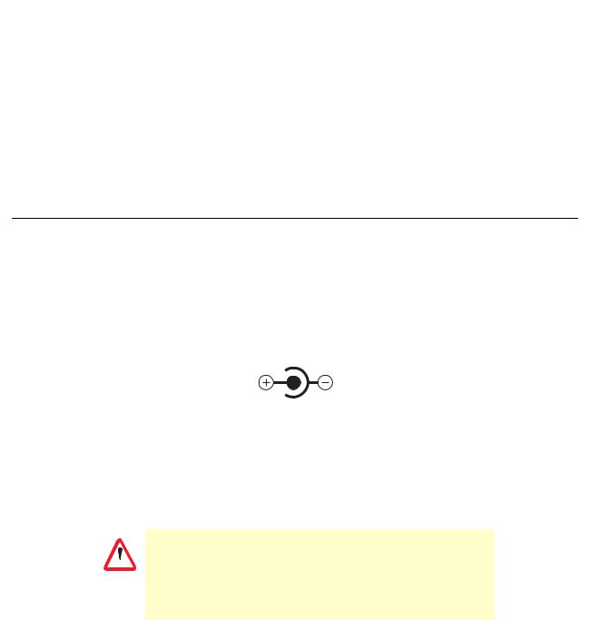
•The power connection to the NTU is a 2.5 mm barrel receptacle with the center conductor positive (see figure 2).
•Rated voltage: 5 VDC
Rated current: 1 A
5 VDC
Figure 2. Power connection barrel receptacle 5 VDC diagram
External AC universal power supply
For additional specifications, see section “Power and power supply specifications” on page 73.
•Output from power supply: 5 VDC, 2 A
•Input to power supply: universal input 100–240 VAC 50/60 Hz 0.3A
The external AC adaptor shall be a listed limited power source that incorporates a disconnect device and shall be positioned
 within easy reach of the operator. Ensure that the AC power CAUTION cable meets all applicable standards for the country in which it is
to be installed, and that it is connected to a wall outlet which has earth ground.
Power input connector |
16 |

Model 3088 Series User Manual |
1 • General information |
|
|
External 48 VDC power supply
The external DC adaptor shall be a listed limited power source that incorporates a disconnect device and shall be positioned within easy reach of the operator. The interconnecting cables
CAUTION shall be rated for the proper voltage, current, anticipated temperature, flammability, and mechanical serviceability
Refer to section “Power and power supply specifications” on page 73 for additional specifications.
•Input
-Rated voltage: 36–60 VDC
-Rated current: 0.25 A DC
-3-pin locking connector, 3.5 mm pitch
-Transient over-voltage protection, 100VDC at 2 ms
•Output
-Rated voltage: 5 VDC ± 5%, 5W
-Rated current; 1 A DC
-6-inch cable terminated with 2.5 mm barrel plug, center positive
Power input connector |
17 |

Chapter 2 |
Configuration |
|
Chapter contents |
|
|
Introduction .......................................................................................................................................................... |
|
19 |
Software (CLI) configuration .......................................................................................................................... |
19 |
|
Hardware (DIP-switch) configuration ............................................................................................................. |
19 |
|
Configuring the DIP switches ......................................................................................................................... |
22 |
|
System reset mode ........................................................................................................................................... |
23 |
|
Software upgrades ..................................................................................................................................... |
23 |
|
Configuration reset to factory defaults ....................................................................................................... |
23 |
|
DIP switch settings ......................................................................................................................................... |
23 |
|
DIP switch settings for RocketLink-G models 3088/CA and 3088/D ............................................................. |
24 |
|
S1-1 through S1-7: Data Rate (RocketLink-G models 3088/CA and 3088/D) ......................................... |
25 |
|
S1-8: TX Clock (RocketLink-G models 3088/CA and 3088/D) ............................................................... |
27 |
|
S2-2: Line Probe (Models 3088/CA and D) .............................................................................................. |
27 |
|
S2-3: Annex A/B (Models 3088/CA and D) .............................................................................................. |
27 |
|
S2-4 through S2-5: Clock Mode (Models 3088/CA and D) ...................................................................... |
27 |
|
X.21 operation. ................................................................................................................................... |
28 |
|
S2-6: DTE Loops (RocketLink-G models 3088/CA only) ........................................................................ |
28 |
|
DIP switch settings for RocketLink-G models 3088/K and 3088/T ................................................................ |
29 |
|
S1-1 through S1-6: TimeSlots & Data Rate (RocketLink-G Models 3088/K and 3088/T) ....................... |
30 |
|
S1-7 and S1-8: Line Build Out (Models 3088/K and 3088/T) .................................................................. |
31 |
|
S2-2 Line Code (Models 3088/K and 3088/T) ......................................................................................... |
31 |
|
S2-3: Annex A/B (Models 3088/K and 3088/T) ....................................................................................... |
31 |
|
S2-4 through S2-5: Clock Mode (Models 3088/K and 3088/T)) .............................................................. |
31 |
|
S2-6 through S2-8: Line Type (Models 3088/K and 3088/T) ................................................................... |
32 |
|
Console ........................................................................................................................................................... |
|
32 |
Help Commands ....................................................................................................................................... |
35 |
|
System Configuration Commands ............................................................................................................ |
35 |
|
System Status Commands ......................................................................................................................... |
36 |
|
DSL Configuration Commands ................................................................................................................ |
36 |
|
DSL Status Command .............................................................................................................................. |
37 |
|
DSL Clear Errcntrs Command .................................................................................................................. |
37 |
|
T1/E1 Configuration Commands ............................................................................................................. |
37 |
|
T1/E1 Status Commands .......................................................................................................................... |
38 |
|
Remote Console |
.............................................................................................................................................. |
38 |
Example Command Line Interface Session ................................................................................................ |
38 |
|
RocketLink Plug ‘n’ Play ................................................................................................................................. |
39 |
|
18
Model 3088 Series User Manual |
2 • Configuration |
|
|
Introduction
You can configure the RocketLink-G (see figure 3) in one of two ways:
•Software configuration using command line interface (CLI) via the console port
•Hardware configuration via DIP switches
Figure 3. RocketLink-G (Model 3088/D shown)
Software (CLI) configuration
To use software configuration you must set all the DIP switches to the ON position before powering-up the RocketLink-G. When all the DIP switches are set to ON the RocketLink-G will operate in software-configura- tion mode. When set for software-configuration mode the RocketLink-G will read any configuration data previously saved to FLASH memory during system power-up. If no configuration data was previously saved to FLASH, then the RocketLink-G will load the factory-default configuration from FLASH memory. After power-up, you may use console commands or the Embedded Operations Channel (EOC) to modify the configuration parameters.
Hardware (DIP-switch) configuration
To use DIP-switch configuration you must first set the DIP switches to a position other than all OFF or all ON before powering-up the RocketLink-G. When all the DIP switches are set to any position other than all OFF or all ON the RocketLink-G will operate in hardware (DIP-switch)-configuration mode. In DIP-switch-configu- ration mode the RocketLink-G will read the DIP-switch settings during system startup and configure itself according to the switch settings.
Once you power-up the RocketLink-G in DIP-switch mode it will operate in DIP-switch mode until powereddown. When operating in DIP-switch mode you cannot change any configuration settings:
•Changing the DIP switch settings while the device is running will not modify the operating configuration because the RocketLink-G only reads the DIP switches during system startup.
•If you attempt to modify the configuration by issuing console commands, the device will not execute your commands. Instead, the RocketLink-G will respond with a message indicating the device is operating in DIP-switch-configuration mode.
Introduction |
19 |

Model 3088 Series User Manual |
2 • Configuration |
|
|
•If you attempt to modify any configuration parameters via the EOC (by changing (EOC variables), the RocketLink-G will not execute your changes.
Table 2 lists the Model 3088’s configurable parameters.
Table 2. RocketLink-G configurable parameters
Parameter |
Description |
Possible Values |
|
|
|
Password |
The password used to login to the console. |
Character strings 1–9 |
|
|
characters long. |
Circuit ID |
The circuit ID used to identify the unit. |
Character string 1–64 |
|
|
characters long. |
|
|
|
Front Panel |
If the device is populated with front panel switches, they can be |
Enabled or Disabled |
Switches |
used to start and stop test modes. If they are disabled, however, |
|
|
the front panel switch settings will be ignored. |
|
DTE Loops |
The V.35 interface can request LALs and RDLs using its RRDL and |
Enabled or Disabled |
(model C) |
RLAL pins. If DTE loops are disabled, requests for loopbacks on |
|
|
these pins will be ignored. |
|
|
|
|
TX Clock |
Defines where (V.35 or X.21) serial transmit data is sampled in |
Normal or Inverted |
(models C, A & D) |
relation to the TX clock: on the falling edge (normal) or the rising |
|
|
edge (inverted) of the TX clock. |
|
DSL Data Rate/ |
Defines the number of DSL timeslots. The DSL data rate is calculated |
1–72 |
Timeslots |
by the equation: data rate = DSL timeslots x 64k. This value also |
|
|
defines the maximum serial/T1/E1 data rate. |
|
|
|
|
Serial/T1/E1 |
Defines the total number of serial/T1/E1 timeslots utilized. This value |
1–72 (V.35) |
Timeslots |
must be less than or equal to DSL timeslots. |
1–72 (X.21) |
|
|
1–24 (T1) |
|
|
1–32 (E1) |
Timeslot |
Defines T1/E1–to–DSL timeslot mapping. By default defined/utilized |
|
Mapping |
DSL timeslots are mapped to the first n data–bearing timeslots on the |
|
(models K & T) |
T1/E1 line. Line type determines which timeslots are data–bearing: |
|
|
T1–Unframed: 1–24a |
|
|
T1–SF: 1–24a |
|
|
T1–ESF: 1–24a |
|
|
E1–Unframed: 0–31 |
|
|
E1–Fractional: 1–31 |
|
|
E1–CRC: 1–31 |
|
|
E1–MF: 1–15,17–31 |
|
|
E1–CRCMF: 1–15,17–31 |
|
|
|
|
Line Type |
Defines the framing format of the T1 or E1 line. |
T1–Unframeda |
(models K & T) |
|
T1–SF (D4)a |
|
|
T1–ESFa |
|
|
E1–Unframed |
|
|
(Clear Channel |
|
|
G.703) |
|
|
E1–Fractional |
|
|
E1–CRC |
|
|
E1–Multiframe |
|
|
E1–CRC & Multiframe |
|
|
|
Introduction |
20 |
Model 3088 Series User Manual |
2 • Configuration |
|
|
Table 2. RocketLink-G configurable parameters (Continued)
Parameter |
Description |
Possible Values |
|
|
|
Line Code |
Selects line coding for the T1 or E1 line. |
AMI |
(models K & T) |
|
HDB3 (E1 only) |
|
|
B8ZS (T1 only) |
|
|
|
Line Build Out |
Selects wave form used on the T1 or E1 line. |
Pulse–75 Ohm(E1) |
(models K & T) |
|
Pulse–120 Ohm (E1) |
|
|
0.0 dB (T1) |
|
|
-7.5 dB (T1) |
|
|
-15.0 dB (T1) |
|
|
-22.5 dB (T1) |
RX Equalizer |
When enabled, this feature removes signal distortion introduced on |
Enabled (select for |
(models K & T) |
the T1 or E1 cable. |
long–haul link). |
|
|
Disabled (select for |
|
|
short–haul link). Long |
|
|
haul LBO (line build- |
|
|
out) is defined by |
|
|
ANSI T1.403). |
|
|
|
Pass Framing |
When enabled, the RocketLink-G transparently passes framing infor- |
Enabled or Disabled. |
(models K & T) |
mation (T1 F-bit or E1 TS0) over the DSL link to the remote T1/E1 net- |
Must always be |
|
work. |
enabled for T1. |
Pass Alarms |
When enabled, the RocketLink-G passes alarms detected on one T1/ |
Enabled or Disabled |
(models K & T) |
E1 network over the DSL link to the remote T1/E1 network. |
|
|
|
|
Clock Mode |
Defines the clock source operation for both DSL and serial/T1/E1 |
Internal |
|
ports as follows. Internal: the on–board oscillator in the 3088 pro- |
External |
|
vides clock for both serial/T1/E1 and DSL lines. External: the |
Receive Recover |
|
serial/T1/E1interface provides clock for the DSL line. Receive |
|
|
Recover: the DSL interface provides clock for the serial/T1/ |
|
|
E1 line. |
|
Annex |
The G.991.2 Annex. |
A or B |
|
|
|
Line Probe |
When this special Patton feature is enabled, the 3088 will set the |
Enabled or Disabled |
|
DSL data rate to the best rate in the 3–36 timeslot range that both |
|
|
NTUs can support. Enable for rate adaptive applications. |
|
Loopback |
The 3088 provides both a local loopback (LAL) and a remote |
OFF, LAL, or RDL |
|
loopback (RDL). This can be used to troubleshoot problems. |
|
|
|
|
Pattern |
The 3088 provides an internal PRBS pattern generator and detec- |
OFF, 511, or 511E |
|
tor that can be used to run BER tests without external equipment. |
|
|
The patterns offered are 511 and 511 with errors. |
|
DSL Error Monitor |
The number of errors allowed in an interval before considering |
0–255 |
Maximum Intervals |
the interval errored. A value of 0 disables the error monitor. |
|
|
|
|
Introduction |
21 |
Model 3088 Series User Manual |
2 • Configuration |
|
|
Table 2. RocketLink-G configurable parameters (Continued)
Parameter |
Description |
Possible Values |
|
|
|
DSL Error Monitor |
The length, in seconds, of an interval. |
1–255 |
Interval Time |
|
|
DSL Error Monitor |
The number of errored intervals allowed before restarting the DSL |
1–255 |
Interval Count |
link. |
|
|
|
|
DSL Error Monitor |
The number of intervals to inspect before disabling the error mon- |
0–255 |
Total Intervals |
itor. |
|
DSL Error Monitor |
The length, in seconds, to wait after DSL link comes up before |
0–255 |
Startup Delay |
enabling the error monitor. |
|
|
|
|
a. For T1 operation, pass framing must be enabled (see Pass Framing parameter for details).
Configuring the DIP switches
The Model 3088 is equipped with two sets of DIP switches, which you can use to configure the RocketLink-G for a broad range of applications. This section describes switch locations and discusses the configuration options available.
Note By default, the RocketLink-G’s DIP switches are all set to “ON” so the NTU can be configured via RocketLink Plug ‘n’ Play from a 3096RC. If that is how you will be configuring the NTU, skip ahead to section “Console” on page 32. Otherwise, read the following sections to manually configure the DIP switch settings.
The two sets of DIP switches are externally accessible from the underside of the Model 3088 (see figure 4).
|
|
|
|
s ed |
oM |
|
|
|
|
|
|
|
|
|
dau |
Q - |
rebi |
|
|
|
|
||
|
|
7G. |
|
|
|
|
|
|
|
|
|
M40RocketLink |
|
|
|
||
7 . |
G/30 |
|
|
|
|
doG- |
|
|
|
|
|
NTUme |
|
|
|
|
|
|
|
|
07. |
G |
|
|
|
|
3 |
|
|
1 |
|
|
407 |
.G/ |
|
|
E491 |
|
tseT |
legin |
S |
|
|||
|
|
|
||||
|
oM |
|
|
|
|
|
F ed |
|
|
|
|
|
|
ledoM
|
|
|
|
|
|
|
|
|
|
|
|
|
1 |
|
|
ON |
|
|
|
|
|
|
|
|
|
|
|
|
|
2 |
|
|
|
|
|
|
|
|
|
|
|
|
|
|
|
|
|
|
|
|
|
|
|
|
|
|
|
|
|
|
|
|
|
3 |
|
|
|
|
|
|
|
|
|
|
|
|
|
|
|
|
|
|
|
|
|
|
|
|
|
|
|
|
|
|
|
|
|
4 |
|
|
|
|
|
|
|
|
|
|
|
|
|
|
|
|
|
|
|
|
|
|
|
|
|
|
|
|
1 |
|
|
ON |
|
5 |
|
|
|
|
|
|
|
|
|
|
|
|
|
|||||||
|
|
|
|
|
|
|
2 |
|
|
|
|
6 |
|
|
|
|
|
|
|
|
|
|
|
|
|
|
|
|
|
|
|||
|
|
|
|
|
|
|
|
3 |
|
|
|
|
7 |
|
|
|
|
|
|
|
|
|
|
|
|
|
|
|
|
|
|||
|
|
|
|
|
|
|
4 |
|
|
|
|
8 |
|
|
|
|
|
|
|
|
|
|
|
|
|
|
|
|
|
|
|||
|
|
|
|
|
|
|
|
5 |
|
|
|
|
|
|
|
|
|
|
|
|
|
|
|
|
|
|
|
|
S1 |
||||
|
|
|
|
|
|
|
|
7 6 |
|
|
|
|
|
|||
|
|
|
|
|
|
|
|
|
|
|
|
|
||||
|
|
|
|
|
|
|
|
|
|
|
|
|
||||
|
|
|
|
|
|
|
|
|
|
|
|
|
||||
|
|
|
|
|
|
|
|
8 |
|
|
|
|
|
|
|
|
|
|
|
|
|
|
|
|
|
|
|
|
|
|
|
|
|
|
|
|
|
|
|
|
|
|
|
|
|
|
|
|
|
|
|
|
|
|
|
|
|
|
|
S2 |
|
|
|
|
|||
3088 C/D Models
|
|
|
|
|
|
|
|
|
|
|
|
|
|
|
8 |
|
|
|
|
|
|
|
|
|
|
|
|
|
|
|
|
|
|
|
|
7 |
|
|
|
|
|
|
|
|
|
|
|
|
|
|
|
|
|
|
|
|
|
|
|
|
|
|
|
|
|
|
|
|
|
|
|
|
|
|
|
|
|
|
|
|
|
|
|
|
|
|
|
|
|
|
|
|
|
|
|
|
|
|
6 |
|
|
|
|
|
|
|
|
|
|
|
|
|
|
|
|
|
|
|
|
|
|
|
|
|
|
|
|
|
|
|
|
|
|
|
|
|
|
|
|
|
5 |
|
|
|
|
|
|
|
|
|
|
|
|
|
|
|
|
|
|
|
|
|
|
|
|
|
|
|
|
|
|
|
|
|
|
|
|
|
|
|
|
|
4 |
|
|
|
|
8 |
|
|
|
|
|
|
|
|
|
|
|
|
|
|
|
|
|
|
|
||
|
|
|
|
|
|
|
|
|
|
|
|
|
|
|
3 |
|
|
|
|
7 |
|
|
|
|
|
|
|
|
|
|
|
|
|
|
|
2 |
|
|
|
|
6 |
|
|
|
|
|
|
|
|
|
|
|
|
|
|
|
|
|
|
|
||
|
|
|
|
|
|
|
|
|
|
|
|
ON |
|
|
1 |
|
|
|
|
5 |
|
|
|
|
|
|
|
|
|
|
|
|
|
|
|
|
|
|
|||
|
|
|
|
|
|
|
|
|
|
|||||||||||
|
|
|
|
|
|
|
|
|
|
|
|
|
|
|
|
|
|
|
4 |
|
|
|
|
|
|
|
|
|
|
|
|
|
|
S1 |
|
|
|
|
|||
|
|
|
|
|
|
|
|
|
|
|
|
|
ON |
|
|
2 3 |
||||
|
|
|
|
|
|
|
|
|
|
|
|
|
|
|
||||||
|
|
|
|
|
|
|
|
|
|
|
|
|
||||||||
|
|
|
|
|
|
|
|
|
|
|
|
|
|
|
||||||
|
|
|
|
|
|
|
|
|
|
|
|
|
|
|
||||||
|
|
|
|
|
|
|
|
|
|
|
|
|
||||||||
|
|
|
|
|
|
|
|
|
|
|
|
|
|
|
|
|
|
|
1 |
|
|
|
|
|
|
|
|
|
|
|
|
|
|
|
|
|
|
|
|
||
|
|
|
|
|
|
|
|
|
|
|
|
|
|
|
|
|
|
|
|
|
|
|
|
|
|
|
|
|
|
|
|
|
|
|
|
|
|
|
S2 |
||
|
|
|
|
seT |
407G. |
|
|
S E4911 l |
|
M |
3088 K/T Models |
|
|
|
|
|
|
/307 |
.G |
e do |
|
||
|
|
|
|
|
|
|
|
|
|||
|
|
|
M t |
|
|
egl |
in |
|
|
|
|
|
|
se |
do |
ed |
o M |
|
|
|
|
|
|
|
|
|
|
|
|
|
|
|
|||
|
|
|
reb |
iF |
|
|
|
|
|
|
|
|
G da |
uQ - |
|
|
|
|
|
|
|
|
|
|
|
|
|
|
|
|
|
|
|
|
|
40RocketLink7. |
|
|
|
|
|
|
|
|
|
|
|
G/307. |
|
|
|
|
|
|
|
|
|
|
|
doMG- |
|
|
|
|
|
|
|
|
|
|
|
meNTU |
|
|
|
|
|
|
|
|
|
|
|
Figure 4. Underside of Model 3088 showing location of DIP switches
Introduction |
22 |

Model 3088 Series User Manual |
2 • Configuration |
|
|
The two sets of DIP switches on the underside of the Model 3088 are referred to as S1 and S2. As shown in figure 5, DIP switch orientation with respect to ON and OFF positions is consistent for all switches.
|
|
|
|
ON |
|
|
|
|
|
|
|
|
|
|
1 |
|
|
|
ON |
|
|
|
||
2 |
|
|
|
|
|
|
|
|
|
3 |
|
|
|
|
|
|
|
|
|
4 |
|
|
|
|
|
|
|
|
|
5 |
|
|
|
|
|
|
|
|
|
6 |
|
|
|
|
|
|
|
|
|
7 |
|
|
|
|
|
|
|
|
|
8 |
|
|
|
|
|
|
|
|
|
|
|
|
|
|
OFF |
|
|
|
|
|
|
|
||
Figure 5. Close-up of configuration switches (all sets are identical appearance)
System reset mode
To enter system reset mode, switch all DIP switches to the OFF position and power cycle the unit. You can use a VT100 emulator configured for 19,200 kbps/1 stop bit/ no parity/ XON-XOFF flow control to access the console. Upon restart, you will see the message “Reset Mode”.
System reset mode provides two functions:
•Software upgrades
•Configuration reset to factory defaults
Software upgrades
The software is upgraded by waiting for the Reset Mode message. Then, the user can send an Intel HEX file supplied by Patton. After the VT100 emulator has finished sending this file, the 3088 will respond with a message stating how many errors were detected. The user may then set the DIP switches to the desired configuration and power cycle the unit to run the upgraded software.
Configuration reset to factory defaults
To recover from a forgotten password, the user may reset the unit to its factory configuration. After seeing the Reset Mode message, the user should type the ‘*’ key. This will result in a ‘:’ prompt. At the prompt, the user should enter the command reset. This will restore the unit to the factory configuration. The unit can then be restarted with the settings in place.
DIP switch settings
You can configure the 3088 by setting the DIP switches to the desired positions before you power up the Rock- etLink-G. If the DIP switches are set to anything other than all OFF or all ON, the RocketLink-G will operate in DIP switch configuration mode. Once the device is powered up and operating in DIP switch configuration mode, you cannot change configuration by any method until you power it down again.
Introduction |
23 |

Model 3088 Series User Manual |
2 • Configuration |
|
|
DIP switch settings for RocketLink-G models 3088/CA and 3088/D
An overview of the RocketLink-G DIP switch functions for Models 3088/CA and 3088/D is provided in table 3 and table 4. The detailed switch settings are shown in following tables.
Table 3. Model 3088/CA and 3088/D - S1 DIP-Switch Functions
Position |
Function |
|
|
S1-1 |
Data Rate |
S1-2 |
|
|
|
S1-3 |
|
S1-4 |
|
|
|
S1-5 |
|
S1-6 |
|
|
|
S1-7 |
|
S1-8 |
TX Clock |
|
|
Table 4. Model 3088/CA and 3088/D - S2 DIP-Switch Functions
Position |
Function |
|
|
S2-1 |
Reserved |
S2-2 |
Line Probe |
|
|
S2-3 |
Annex |
S2-4 |
Clock Mode |
|
|
S2-5 |
|
S2-6 |
DTE Loops |
|
|
S2-7 |
Reserved |
S2-8 |
|
|
|
Introduction |
24 |

Model 3088 Series User Manual |
2 • Configuration |
|
|
S1-1 through S1-7: Data Rate (RocketLink-G models 3088/CA and 3088/D)
Switches S1-1 through S1-7 define both the DSL data rate and the serial data rate.
Table 5. S1-1 through S1-7 Data Rate DIP switch settings
S1-1 |
S1-2 |
S1-3 |
S1-4 |
S1-5 |
S1-6 |
S1-7 |
Data Rate (kbps) |
|
|
|
|
|
|
|
|
OFF |
ON |
ON |
ON |
ON |
ON |
ON |
64 |
ON |
OFF |
ON |
ON |
ON |
ON |
ON |
128 |
|
|
|
|
|
|
|
|
OFF |
OFF |
ON |
ON |
ON |
ON |
ON |
192 |
ON |
ON |
OFF |
ON |
ON |
ON |
ON |
256 |
|
|
|
|
|
|
|
|
OFF |
ON |
OFF |
ON |
ON |
ON |
ON |
320 |
ON |
OFF |
OFF |
ON |
ON |
ON |
ON |
384 |
|
|
|
|
|
|
|
|
OFF |
OFF |
OFF |
ON |
ON |
ON |
ON |
448 |
ON |
ON |
ON |
OFF |
ON |
ON |
ON |
512 |
|
|
|
|
|
|
|
|
OFF |
ON |
ON |
OFF |
ON |
ON |
ON |
576 |
ON |
OFF |
ON |
OFF |
ON |
ON |
ON |
640 |
|
|
|
|
|
|
|
|
OFF |
OFF |
ON |
OFF |
ON |
ON |
ON |
704 |
ON |
ON |
OFF |
OFF |
ON |
ON |
ON |
768 |
|
|
|
|
|
|
|
|
OFF |
ON |
OFF |
OFF |
ON |
ON |
ON |
832 |
ON |
OFF |
OFF |
OFF |
ON |
ON |
ON |
896 |
|
|
|
|
|
|
|
|
OFF |
OFF |
OFF |
OFF |
ON |
ON |
ON |
960 |
ON |
ON |
ON |
ON |
OFF |
ON |
ON |
1024 |
|
|
|
|
|
|
|
|
OFF |
ON |
ON |
ON |
OFF |
ON |
ON |
1088 |
ON |
OFF |
ON |
ON |
OFF |
ON |
ON |
1152 |
|
|
|
|
|
|
|
|
OFF |
OFF |
ON |
ON |
OFF |
ON |
ON |
1216 |
ON |
ON |
OFF |
ON |
OFF |
ON |
ON |
1280 |
|
|
|
|
|
|
|
|
OFF |
ON |
OFF |
ON |
OFF |
ON |
ON |
1344 |
ON |
OFF |
OFF |
ON |
OFF |
ON |
ON |
1408 |
|
|
|
|
|
|
|
|
OFF |
OFF |
OFF |
ON |
OFF |
ON |
ON |
1472 |
ON |
ON |
ON |
OFF |
OFF |
ON |
ON |
1536 |
|
|
|
|
|
|
|
|
OFF |
ON |
ON |
OFF |
OFF |
ON |
ON |
1600 |
ON |
OFF |
ON |
OFF |
OFF |
ON |
ON |
1664 |
|
|
|
|
|
|
|
|
OFF |
OFF |
ON |
OFF |
OFF |
ON |
ON |
1728 |
ON |
ON |
OFF |
OFF |
OFF |
ON |
ON |
1792 |
|
|
|
|
|
|
|
|
OFF |
ON |
OFF |
OFF |
OFF |
ON |
ON |
1856 |
ON |
OFF |
OFF |
OFF |
OFF |
ON |
ON |
1920 |
|
|
|
|
|
|
|
|
OFF |
OFF |
OFF |
OFF |
OFF |
ON |
ON |
1984 |
ON |
ON |
ON |
ON |
ON |
OFF |
ON |
2048 |
|
|
|
|
|
|
|
|
OFF |
ON |
ON |
ON |
ON |
OFF |
ON |
2112 |
ON |
OFF |
ON |
ON |
ON |
OFF |
ON |
2176 |
|
|
|
|
|
|
|
|
OFF |
OFF |
ON |
ON |
ON |
OFF |
ON |
2240 |
ON |
ON |
OFF |
ON |
ON |
OFF |
ON |
2304 |
|
|
|
|
|
|
|
|
Introduction |
25 |
Loading...