


 Loading...
Experiment Guide
013-13906B
Complete Microwave Optics System
WA-9316A
Experiment Guide
See the PASCO Web site at www.pasco.com for information about the Complete Microwave Optics System.
Important Note
•CAUTION — Under some circumstances, microwaves can interfere with electronic medical devices. If you use a pacemaker, or other electronic medical device, check with your doctor or the manufacturer to be certain that low power microwaves at a frequency of 10.525 GHz will not interfere with its operation.

Experiment Guide
Table Of Contents
Introduction - - - - - - - - - - - - - - - - - - - - - - - - - - - - - - - - - - - - - - - - - - - - - - - - - - - - - - - - - - - - - - - - - - - - - - - - - - - - 3 Microwave Optics System Equipment - - - - - - - - - - - - - - - - - - - - - - - - - - - - - - - - - - - - - - - - - - - - - - - - - - - - - - - - - - 3 Technical Support - - - - - - - - - - - - - - - - - - - - - - - - - - - - - - - - - - - - - - - - - - - - - - - - - - - - - - - - - - - - - - - - - - - - - - - - 4 Experiments
Experiment 1: Introduction to the Microwave Optics System- - - - - - - - - - - - - - - - - - - - - - - - - - - - - - - - - - - - - - - - 5 Experiment 2: Reflection - - - - - - - - - - - - - - - - - - - - - - - - - - - - - - - - - - - - - - - - - - - - - - - - - - - - - - - - - - - - - - - - 9 Experiment 3: Standing Waves - Measuring Wavelengths - - - - - - - - - - - - - - - - - - - - - - - - - - - - - - - - - - - - - - - - - -11 Experiment 4: Refraction Through a Prism - - - - - - - - - - - - - - - - - - - - - - - - - - - - - - - - - - - - - - - - - - - - - - - - - - - -15 Experiment 5: Polarization- - - - - - - - - - - - - - - - - - - - - - - - - - - - - - - - - - - - - - - - - - - - - - - - - - - - - - - - - - - - - - -17 Experiment 6: Double-Slit Interference - - - - - - - - - - - - - - - - - - - - - - - - - - - - - - - - - - - - - - - - - - - - - - - - - - - - - -19 Experiment 7: Lloyds Mirror - - - - - - - - - - - - - - - - - - - - - - - - - - - - - - - - - - - - - - - - - - - - - - - - - - - - - - - - - - - - -21 Experiment 8: Fabry-Perot Interferometer - - - - - - - - - - - - - - - - - - - - - - - - - - - - - - - - - - - - - - - - - - - - - - - - - - - -23 Experiment 9: Michelson Interferometer - - - - - - - - - - - - - - - - - - - - - - - - - - - - - - - - - - - - - - - - - - - - - - - - - - - - -25 Experiment 10: Fiber Optics- - - - - - - - - - - - - - - - - - - - - - - - - - - - - - - - - - - - - - - - - - - - - - - - - - - - - - - - - - - - - -27 Experiment 11: Brewster’s Angle - - - - - - - - - - - - - - - - - - - - - - - - - - - - - - - - - - - - - - - - - - - - - - - - - - - - - - - - - -28 Experiment 12: Bragg Diffraction - - - - - - - - - - - - - - - - - - - - - - - - - - - - - - - - - - - - - - - - - - - - - - - - - - - - - - - - - -31
(Note that Experiment 3 can be done with the WA-9319A Microwave Detector Probe and that Experiment 11 and Experiment 12 use equipment from the WA-9315 Microwave Accessory Package.)
Teacher’s Guide - - - - - - - - - - - - - - - - - - - - - - - - - - - - - - - - - - - - - - - - - - - - - - - - - - - - - - - - - - - - - - - - - - - - - - - - -33
2
013-13906B |
Introduction |
Introduction
The experiments are designed to give a thorough introduction to wave theory using the Microwave Optics System. Basic principles are only briefly discussed in each experiment because it is assumed that the students have the appropriate theoretical background. These experiments range from quantitative investigation of reflection and refraction to microwave models of the Michelson and Fabry-Perot interferometers. Experiments for investigating Bragg diffraction and Brewster’s angle are included, but require the Microwave Accessory Package.
The experiments are written in a worksheet format. Fee free to copy the experiment write-ups for use in your lab.
Microwave Optics System Equipment
The Complete Microwave Optics System consists of the Microwave Optics System (WA-9314C) and the Microwave Accessory Package (WA-9315). The Microwave Optics System comes with a 2.85 centimeter wavelength microwave transmitter and a receiver with variable amplification from 1X to 30X. All the accessory equipment needed to investigate a variety of wave phenomena is also included.
Microwave Optics System (WA-9314C) |
Microwave Optics System (WA-9314C) |
|
|
Microwave Receiver WA-9800 |
Metal Reflectors (2) |
|
|
Microwave Transmitter WA-9801 |
Partial Reflectors (2) |
|
|
Mounting Stands (2) WA-9802 |
Polarizers (2) |
|
|
Power Adapters (2) |
Slit Extender Arm |
|
|
Goniometer |
Narrow Slit Spacer |
|
|
Fixed Arm Assembly |
Wide Slit Spacer |
|
|
Rotating Table |
Ethafoam Prism Mold |
|
|
Component Holders (2) |
Styrene Pellets (1 jar) |
|
|
Rotating Component Holder |
Tubular Plastic Bags (4) |
|
|
.
Microwave Accessory Package (WA-9315)
Cubic Lattice* (Bragg’s crystal model)
Polyethylene Panel
*The Cubic Lattice contains 100 metal spheres in a 5 by 5 by 4 array.
Assembling Equipment for Experiments
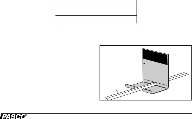
The arms of the Goniometer or the Fixed Arm Assembly slide through the holes in the Component Holders as shown. Make sure the magnetic strip on the bottom of the arm grips the base of the carriage. To adjust the position of the holders, just slide them along the arms. Attach the mounting stands of the microwave Transmitter and Receiver to the arms of the Goniometer or Fixed Arm Assembly in the same manner.
For most experiments it is advantageous to attach the Transmitter to the long arm of the Goniometer and the Receiver to the shorter, rotatable arm. This maintains a fixed relationship between the microwave beam and components mounted on the long arm (or on the degree plate) of the Goniometer. In turn the Receiver moves easily to sample the output.
Holder |
Arm |
3 |

Experiment Guide |
Technical Support |
|
|
|
|
Reflectors, Partial Reflectors, Polarizers, Slit Spacers, and the Slit Extender Arm all attach magnetically to the Component Holders. The metric scale along the Goniometer and Fixed Arm Assembly arms and the degree plate at the junction of the Goniometer arms allow easy measurement of component placement.
•It is recommended that the apparatus be mounted on a CLEAN, SMOOTH table.
•Before setting up the equipment, brush off any material—particularly metal chips—that might have adhered to the magnetic strips and magnetic pads.
Maintenance
Regular maintenance for this equipment is minimal. When not in use, the equipment can be stored in the shipping box. Inspect the magnetic strips and magnetic pads and remove anything - especially bits of metal - that adhere to them.
If problems arise with the equipment DO NOT attempt to fix this equipment yourself. Contact PASCO scientific. (See the Technical Support information.)
Technical Support
For assistance with any PASCO product, contact PASCO at:
Address: PASCO scientific 10101 Foothills Blvd.
Roseville, CA 95747-7100
Phone: +1 916 786 3800 (worldwide) 800-772-8700 (U.S.)
E-mail: support@pasco.com Web www.pasco.com
For the latest information about the Complete Microwave Optics System or its accessories,
go to the PASCO web site at www.pasco.com and enter the model number or the product name in the search window.
Limited Warranty For a description of the product warranty, see the PASCO catalog. Copyright The PASCO scientific Experiment Guide is copyrighted with all rights reserved. Permission is granted to non-profit educational institutions for reproduction of any part of this manual, providing the reproductions are used only in their laboratories and classrooms, and are not sold for profit. Reproduction under any other circumstances, without the written consent of PASCO scientific, is prohibited. Trademarks PASCO, PASCO Capstone, PASPORT, SPARK Science Learning System, SPARK SLS, and SPARKvue are trademarks or registered trademarks of PASCO scientific, in the United States and/or in other countries. For more information visit www.pasco.com/legal.
Product End of Life Disposal Instructions:
This electronic product is subject to disposal and recycling regulations that vary by country and region. It is your responsibility to recycle your electronic equipment per your local environmental laws and regulations to ensure that it will be recycled in a manner that protects human health and the environment. To find out where you can drop off your waste equipment for recycling, please contact your local waste recycle/disposal service, or the place where you purchased the product.
The European Union WEEE (Waste Electronic and Electrical Equipment) symbol (to the right) and on the product or its packaging indicates that this product must not be disposed of in a standard waste container.
4
013-13906B |
Experiment 1: Introduction to the Microwave Optics System |
Experiment 1: Introduction to the Microwave Optics System
Equipment Needed:
Item |
Item |
|
|
|
|
|
Transmitter |
Goniometer |
|
Receiver |
Reflector |
Purpose |
|
|
This activity gives an introduction to the Microwave Optics System which may prove helpful in learning to use the equipment effectively and in understanding the significance of measurements made with this equipment.
Procedure
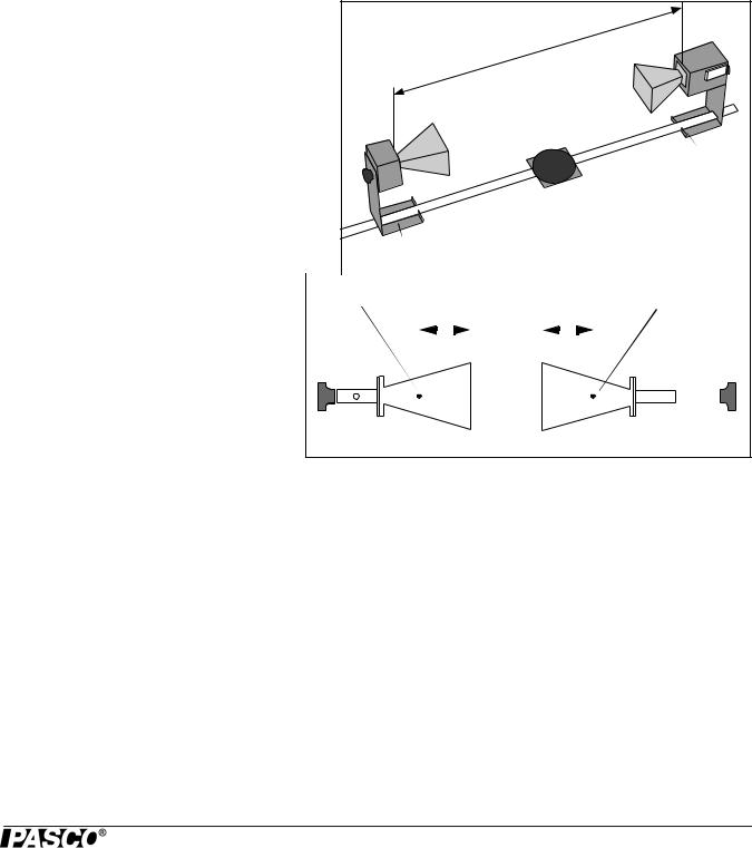
1. Arrange the Transmitter and Receiver on the Goni- |
R |
|||||||||||||||||
ometer as shown in Figure 1 with the Transmitter |
|
|
|
|
|
|
|
|
|
|
||||||||
attached to the fixed arm. Be sure to adjust both |
|
|
|
|
|
|
|
|
|
|
||||||||
Transmitter and Receiver to the same polarity — the |
|
|
|
|
|
|
|
|
|
|
||||||||
horns should have the same orientation, as shown. |
|
|
|
|
|
|
|
|
|
|
||||||||
2. Plug in the Transmitter and the Receiver. Turn the |
|
|
|
|
|
|
|
R |
||||||||||
INTENSITY selection switch on the Receiver from |
|
|
|
|
T |
|||||||||||||
OFF to 10X. (The LEDs should light up on both |
|
|
|
|
|
|
|
|
|
|
||||||||
units.) |
|
|
|
|
|
|
|
|
|
|
|
|
|
|
|
|
|
|
|
|
|
|
|
T |
Figure1.1: Equipment Setup |
||||||||||||
|
|
|
|
|
|
|
|
|
||||||||||
3. Adjust the Transmitter and Receiver so the |
|
|
|
|
|
|
|
|
|
|
|
|
|
|
|
|
|
|
Effective Point of Emission of |
|
|
|
|
Effective Point of Reception |
|||||||||||||
distance between the source diode in the |
|
|
Transmitter Signal |
|
|
|
|
of Transmitter Signal |
||||||||||
Transmitter and the detector diode in the |
|
|
|
|
|
|
|
|
|
|
|
|
|
|
|
|
|
|
Receiver (the distance labeled R in Figure 1) |
|
|
|
|
|
|
|
|
|
|
|
|
|
|
|
|
|
|
|
|
|
|
|
|
|
|
|
|
|
|
|
|
|
|
|
|
|
is 40 cm (see Figure 1.2 for location of points |
|
|
|
|
|
5 cm |
|
5 cm |
|
|||||||||
of transmission and reception). The diodes are |
|
|
|
|
|
|
|
|
|
|
|
|
|
|
|
|
|
|
|
|
|
|
|
|
|
|
|
|
|
|
|
|
|
|
|
|
|
at the locations directly above the points |
|
|
|
|
|
|
|
|
|
|
|
|
|
|
|
|
|
|
marked “T” and “R” on the stands. Adjust the |
|
|
|
|
|
|
|
|
|
|
|
|
|
|
|
|
|
|
INTENSITY and VARIABLE SENSITIVITY |
|
|
|
|
|
|
|
|
|
|
|
|
|
|
|
|
|
|
knobs on the Receiver so that the meter reads |
|
|
|
|
|
|
Figure1.2: Equipment Setup |
|||||||||||
1.0 (full scale).
4.Set the distance R to each of the values shown in Table 1. Record the meter reading for each value of R. (Do not adjust the Receiver controls between measurements.) After making the measurements, perform the calculations shown in the table.
Table 1.1: Data
R (cm) |
Meter Reading (M) |
M X R (cm) |
M X R2 (cm2) |
40 |
|
|
|
|
|
|
|
50 |
|
|
|
|
|
|
|
60 |
|
|
|
|
|
|
|
70 |
|
|
|
|
|
|
|
80 |
|
|
|
|
|
|
|
90 |
|
|
|
|
|
|
|
100 |
|
|
|
|
|
|
|
5
Experiment Guide |
Experiment 1: Introduction to the Microwave Optics System |
|
|
|
|
5.Set R to some value between 70 and 90 cm. While watching the meter, slowly decrease the distance between the Transmitter and Receiver. Does the meter deflection increase steadily as the distance decreases?
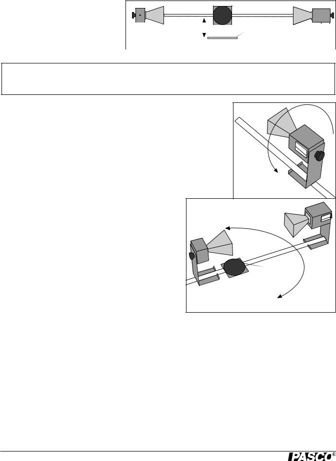
6.Set R to between 50 and 90 cm. Move a Reflector, its plane parallel to the axis of
the microwave beam, toward and away |
|
|
|
|
|
|
|
|
|
|
|
|
|
|
|
|
|
|
|
||
from the beam axis, as shown in Figure |
|
|
|
|
Reflector |
|||||
1.3. Observe the meter readings. Can you |
|
|
|
|
||||||
|
|
|
|
|||||||
explain your observations in steps 5 and |
|
Figure1.3: Reflections |
||||||||
6? (Don’t worry if you can’t; you will |
|
|
|
|
|
|
|
|
|
|
|
|
|
|
|
|
|
|
|
||
have a chance to investigate these phenomena more closely in other experiments.) For now just be aware of the following:
IMPORTANT: Reflections from nearby objects, including the table top, can affect the results of your microwave experiments. To reduce the effects of extraneous reflections, keep your experiment table clear of all objects, especially metal objects, other than those components required for the current experiment.
7.Loosen the hand screw on the back of the Receiver and rotate the Receiver as shown in Figure 1.4. This varies the polarity of maximum detection. (Look into the receiver horn and notice the alignment of the detector diode.) Observe the meter readings through a full 360 degree rotation of the horn. A small mirror may be helpful to view the meter reading as the receiver is turned. At what polarity
does the Receiver detect no signal?
NOTE: Try rotating the Transmitter horn as well. When finished, reset the Transmitter and Receiver so their polarities match (e.g., both horns are horizontal or both horns are vertical).
Figure1.4: Polarization
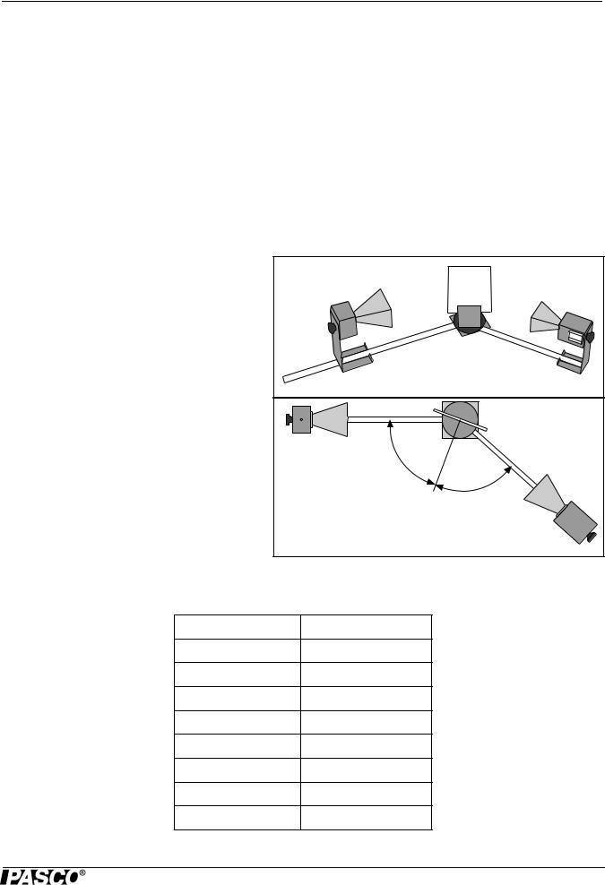
8.Position the Transmitter so the output surface of the horn is centered directly over the center of the Degree Plate of the Goni-
ometer arm (see Figure 1.5). With the Receiver directly facing |
|
the Transmitter and as far back on the Goniometer arm as possi- |
|
ble, adjust the Receiver controls for a meter reading of 1.0. |
|
Then rotate the rotatable arm of the Goniometer as shown in the |
|
figure. Set the angle of rotation (measured relative to the |
|
180-degree point on the degree scale) to each of the values |
|
shown in Table 2, and record the meter reading at each setting |
Angle = 180° |
|
Figure1.5: Signal Distribution
.
Table 1.2: Data
Angle of |
Meter |
Angle of |
Meter |
Angle of |
Meter |
Receiver |
Reading |
Receiver |
Reading |
Receiver |
Reading |
|
|
|
|
|
|
90° |
|
160 |
|
230 |
|
|
|
|
|
|
|
100 |
|
170 |
|
240 |
|
|
|
|
|
|
|
110 |
|
180 |
|
250 |
|
|
|
|
|
|
|
120 |
|
190 |
|
260 |
|
|
|
|
|
|
|
130 |
|
200 |
|
270 |
|
|
|
|
|
|
|
140 |
|
210 |
|
|
|
|
|
|
|
|
|
150 |
|
220 |
|
|
|
|
|
|
|
|
|
6

013-13906B |
Experiment 1: Introduction to the Microwave Optics System |
Questions
1.The electric field of an electromagnetic wave is inversely proportional to the distance from the wave source, (i.e.,
E = 1/R). Use your data from step 4 of the experiment to determine if the meter reading of the Receiver is directly proportional to the electric field of the wave.
2.The intensity of an electromagnetic wave is inversely proportional to the square of the distance from the wave source (i.e., I = 1/R2). Use your data from step 4 of the experiment to determine if the meter reading of the Receiver is directly proportional to the intensity of the wave.
3.Considering your results in step 7, to what extent can the Transmitter output be considered a spherical wave? A plane wave?
7

Experiment Guide |
Experiment 1: Introduction to the Microwave Optics System |
|
|
|
|
8
013-13906B Experiment 2: Reflection
Experiment 2: Reflection
Equipment Needed:
|
Item |
Item |
|
|
|
|
Transmitter |
Goniometer |
|
Receiver |
Metal Reflector |
|
Rotating Component Holder |
|
Purpose |
|
|
This experiment explores the relationship of reflected microwaves to incident microwaves when the incident microwaves encounter a flat reflector at some angle measured from the normal of the reflector.
Procedure
1.Arrange the equipment as shown in Figure 2.1 with the Transmitter attached to the fixed arm of the Goniometer. Be sure to adjust the Transmitter and Receiver to the same polarity; the horns should have the same orientation as shown.
2.Plug in the Transmitter and turn the Receiver INTENSITY selection switch to 30X.
3.The angle between the incident wave from the Transmitter and a line normal to the plane of the Reflector is called the Angle of Incidence (see Figure 2.2). Adjust the Rotating Component Holder so that the Angle of Incidence equals 45°.
4.Without moving the Transmitter or the Reflector, rotate the movable arm of the Goniometer until the meter reading is a maximum. The angle between the axis of the Receiver horn and a line normal to the plane of the Reflector is called the Angle of Reflection.
Figure 2.1: Equipment Setup |
Figure 2.2: Angles of Incidence and Reflection |
5.Measure and record the angle of reflection for each of the angles of incidence shown in Table 2.1.
Table 2.1: Data
Angle of Incidence |
Angle of Reflection |
20°
30°
40°
50°
60°
70°
80°
90°
NOTE: At various angle settings the Receiver will detect both the reflected wave and the wave coming directly from the Transmitter, thus giving misleading results. Determine the angles for which this is true and mark the data collected at these angles with an asterisk (“*”).
9

Experiment Guide |
Experiment 2: Reflection |
|
|
|
|
Questions
1.What relationship holds between the angle of incidence and the angle of reflection? Does this relationship hold for all angles of incidence?
2.In measuring the angle of reflection, you measured the angle at which a maximum meter reading was found. Can you explain why some of the wave reflected into different angles? How does this affect your answer to question 1?
3.Ideally you would perform this experiment with a perfect plane wave, so that all the Transmitter radiation strikes the Reflector at the same angle of incidence. Is the microwave from the Transmitter a perfect plane wave (see Experiment 1, step 7)? Would you expect different results if it were a perfect plane wave? Explain.
Questions for Additional Experimentation
1.How does reflection affect the intensity of the microwave? Is all the energy of the wave striking the Reflector reflected? Does the intensity of the reflected signal vary with the angle of incidence?
2.Metal is a good reflector of microwaves. Investigate the reflective properties of other materials. How well do they reflect? Does some of the energy pass through the material? Does the material absorb some of it? Compare the reflective properties of conductive and non-conductive materials.
10
013-13906B |
Experiment 3: Standing Waves – Measuring Wavelength |
Experiment 3: Standing Waves – Measuring Wavelength
Equipment Needed:
|
Item |
Item |
|
|
|
|
Transmitter |
Goniometer |
|
Receiver |
Reflector |
|
Component Holder (2) |
Optional: Microwave Detector Probe |
Introduction |
|
|
When two electromagnetic waves meet in space, they superpose. The superposition principle describes that the total electric field at any point is the sum of the electric fields created by both waves at that point. If the two waves travel at the same frequency but in opposite direction, they form a standing wave. Nodes appear where the fields of the two waves cancel and antinodes appear where the superposed fields oscillate between a maximum and a minimum. The distance between nodes in the standing wave pattern is just one-half (1/2) the wavelength, of the two waves.
Purpose
In this experiment, you will reflect the wave from the Transmitter back upon itself, creating a standing wave pattern. By measuring the distance between nodes in the pattern and multiplying by two, you can determine the wavelength, , of the microwave radiation.
Procedure
Method A
1.Set up the equipment as shown in Figure 3.1. Adjust the Receiver controls to get a full-scale
meter reading with the Transmitter and Receiver as close together as possible. Slowly move the Receiver along the Goniometer arm away from the Transmitter. How does this motion effect the meter reading?
NOTE: The microwave horns are not perfect collectors of microwave radiation. Instead, they act as par-
tial reflectors, so that the radiation from the Transmitter reflects back and forth between the
Transmitter and Reflector horns, diminishing in amplitude at each pass. However, if the distance
between the Transmitter and Receiver diodes is equal to n /2, (where n is an integer and is the wavelength of the radiation), then all the multiply-reflected waves entering the Receiver horn will be in phase with the primary transmitted wave. When this occurs, the meter reading will be a maximum. (The distance between adjacent positions in order to see a maximum is therefore/2.)
2.Slide the Receiver one or two centimeters along the Goniometer arm to obtain a maximum meter reading. Record the Receiver position along the metric scale of the Goniometer arm.
• |
Initial Position of Receiver = _________________________. |
3. |
While watching the meter, slide the Receiver away from the Transmitter. Do not stop until the Receiver passed through at |
|
least 10 positions at which you see a minimum meter reading and it returned to a position where the reading is a maxi- |
|
mum. Record the new position of the Receiver and the number of minima that were traversed. |
• |
Minima Traversed= _________________________. |
• |
Final Receiver Position = _________________________. |
4.Use the data you have collected to calculate the wavelength of the microwave radiation.
11
Experiment Guide |
Experiment 3: Standing Waves – Measuring Wavelength |
|
|
|
|
•= _________________________.
5.Repeat your measurements and recalculate l.
•Initial Position of Receiver = _________________________.
•Minima Traversed = _________________________.
•Final Receiver Position = _________________________.
•= _________________________.
Question
Use the relationship velocity = to calculate the frequency, , of the microwave signal (assuming velocity of propagation in air is 3 x 10⁸ m/s).
( = the expected frequency of the microwave radiation - 10.525 GHz).
NOTE: This experiment can also be performed using the PASCO Microwave Detector Probe (Model ME-9319A), as described in Method B below. Method A can be used for those without a probe. However, in Method A, the wavelength, can not be measured directly from the standing wave pattern. In Method B, the wavelength can be measured directly from the standing wave pattern.
Method B
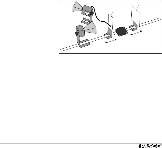
1. Arrange the equipment as shown in Fig- |
Receiver |
Reflector |
|
ure 3.1. |
|||
|
Detector |
||
|
|
Probe |
2. Plug the Detector Probe into the EXTERNAL ANTENNA connector on the Receiver. Face the Receiver horn directly away from the Transmitter so that none of the microwave signal enters the horn. Adjust the Receiver controls as needed to get a strong meter reading.
3. Slide the Probe along the Goniometer arm (no more than a centimeter or two)
until the meter shows a maximum read-
ing. Then slide the Reflector (again, no more than a centimeter or two) to find a maximum meter reading. Continue making slight adjustments to the Probe and Reflector positions until the meter reading is as high as possible.
4.Now find a node of the standing wave pattern by adjusting the Probe until the meter reading is a minimum. Record the Probe Position along the metric scale on the Goniometer arm.
• |
Initial Probe Position = _____________________. |
5. |
While watching the meter, slide the Probe along the Goniometer arm until the Probe has passed through at least 10 |
|
antinodes and returned to a node. Record the new position of the Probe and the number of antinodes that were traversed. |
• |
Antinodes Traversed= __________________________. |
• |
Final Probe Position = _________________________. |
6.Use your data to calculate , the wavelength of the microwave radiation.
=_________________________.
7.Repeat your measurements and recalculate .
•Initial Probe Position =_________________________.
•Antinodes Traversed =_________________________.
12

013-13906B |
Experiment 3: Standing Waves – Measuring Wavelength |
•Final Probe Position =_________________________.
•=_________________________.
Question
Use the relationship velocity = to calculate the frequency, , of the microwave signal (assuming velocity of propagation in air is 3 x 10⁸ m/s).
( = the expected frequency of the microwave radiation - 10.525 GHz).
13
Loading...