


 Loading...
HOTWIRE 7975
M/SDSL STANDALONE TERMINATION UNIT
USER'S GUIDE
Document No. 7975-A2-GB20-40
December 1998

Copyright E 1998 Paradyne Corporation.
All rights reserved.
Printed in U.S.A.
Notice
This publication is protected by federal copyright law. No part of this publication may be copied or distributed, transmitted, transcribed, stored in a retrieval system, or translated into any human or computer language in any form or by any means, electronic, mechanical, magnetic, manual or otherwise, or disclosed to third parties without the express written permission of Paradyne Corporation, 8545 126th Ave. N., Largo, FL 33773.
Paradyne Corporation makes no representation or warranties with respect to the contents hereof and specifically disclaims any implied warranties of merchantability or fitness for a particular purpose. Further, Paradyne Corporation reserves the right to revise this publication and to make changes from time to time in the contents hereof without obligation of Paradyne Corporation to notify any person of such revision or changes.
Changes and enhancements to the product and to the information herein will be documented and issued as a new release to this manual.
Warranty, Sales, and Service Information
Contact your local sales representative, service representative, or distributor directly for any help needed. For additional information concerning warranty, sales, service, repair, installation, documentation, training, distributor locations, or Paradyne worldwide office locations, use one of the following methods:
HVia the Internet: Visit the Paradyne World Wide Web site at http://www.paradyne.com
HVia Telephone: Call our automated call system to receive current information via fax or to speak with a company representative.
ÐWithin the U.S.A., call 1-800-870-2221
ÐOutside the U.S.A., call 1-727-530-2340
Trademarks
All products and services mentioned herein are the trademarks, service marks, registered trademarks or registered service marks of their respective owners.
Document Feedback
We welcome your comments and suggestions about this document. Please mail them to Technical Publications, Paradyne Corporation, 8545 126th Ave. N., Largo, FL 33773, or send e-mail to userdoc@eng.paradyne.com. Include the number and title of this document in your correspondence. Please include your name and phone number if you are willing to provide additional clarification.
Printed on recycled paper
A |
December 1998 |
7975-A2-GB20-40 |

Important Information
Important Safety Instructions
1.Read and follow all warning notices and instructions marked on the product or included in the manual.
2.Input power to this product must be provided by one of the following: (1) a UL Listed/CSA Certified power source with a Class 2 or Limited Power Source (LPS) output for use in North America; or (2) a 24 Vdc National Electric Code (NEC) ANSI/NFPA 70/Canadian Electric Code (CEC) Class 2 circuit installed in accordance with articles 110-16, 110-17, and 110-18 of the NEC, and articles 2-308, 2-310, 2-312, 2-314, 2-200, and 2-202 of the CEC, or
(3)a Safety Extra Low Voltage (SELV) power source with a maximum available output of less than 240 VA, certified for use in the country of installation.
3.Slots and openings in the cabinet are provided for ventilation. To ensure reliable operation of the product and to protect it from overheating, these slots and openings must not be blocked or covered.
4.Do not allow anything to rest on the power cord and do not locate the product where persons will walk on the power cord.
5.Do not attempt to install or service this product yourself, as opening or removing covers may expose you to dangerous high voltage points or other risks. Refer all installation and servicing to qualified service personnel.
6.General purpose cables are provided with this product. Special cables, which may be required by the regulatory inspection authority for the installation site, are the responsibility of the customer.
7.When installed in the final configuration, the product must comply with the applicable Safety Standards and regulatory requirements of the country in which it is installed. If necessary, consult with the appropriate regulatory agencies and inspection authorities to ensure compliance.
8.A rare phenomenon can create a voltage potential between the earth grounds of two or more buildings. If products installed in separate buildings are interconnected, the voltage potential may cause a hazardous condition. Consult a qualified electrical consultant to determine whether or not this phenomenon exists and, if necessary, implement corrective action prior to interconnecting the products.
9.In addition, if the equipment is to be used with telecommunications circuits, take the following precautions:
Ð Never install telephone wiring during a lightning storm.
Ð Never install telephone jacks in wet locations unless the jack is specifically designed for wet locations.
Ð Never touch uninsulated telephone wires or terminals unless the telephone line has been disconnected at the network interface.
Ð Use caution when installing or modifying telephone lines.
Ð Avoid using a telephone (other than a cordless type) during an electrical storm. There may be a remote risk of electric shock from lightning.
Ð Do not use the telephone to report a gas leak in the vicinity of the leak.
7975-A2-GB20-40 |
December 1998 |
B |

Important Information
EMI Warnings
! WARNING:
This equipment has been tested and found to comply with the limits for a Class A digital device, pursuant to Part 15 of the FCC rules. These limits are designed to provide reasonable protection against harmful interference when the equipment is operated in a commercial environment. This equipment generates, uses, and can radiate radio frequency energy and, if not installed and used in accordance with the instruction manual, may cause harmful interference to radio communications. Operation of this equipment in a residential area is likely to cause harmful interference in which case the user will be required to correct the interference at his own expense.
The authority to operate this equipment is conditioned by the requirements that no modifications will be made to the equipment unless the changes or modifications are expressly approved by Paradyne Corporation.
! WARNING:
To Users of Digital Apparatus in Canada:
This Class A digital apparatus meets all requirements of the Canadian interference-causing equipment regulations.
Cet appareil numérique de la classe A respecte toutes les exigences du règlement sur le matérial brouilleur du Canada.
C |
December 1998 |
7975-A2-GB20-40 |

Contents
About This Guide
H Document Purpose and Intended Audience . . . . . . . . . . . . . . . . . . . . . . . . . |
v |
|
H |
Document Summary . . . . . . . . . . . . . . . . . . . . . . . . . . . . . . . . . . . . . . . . . . . . . |
v |
H |
Product-Related Documents . . . . . . . . . . . . . . . . . . . . . . . . . . . . . . . . . . . . . . |
vi |
1 About the Hotwire 7975 Standalone Termination Unit
H |
M/SDSL Overview . . . . . . . . . . . . . . . . . . . . . . . . . . . . . . . . . . . . . . . . . . . . . . |
1-1 |
H |
Hotwire 7975 Features . . . . . . . . . . . . . . . . . . . . . . . . . . . . . . . . . . . . . . . . . . . |
1-2 |
H |
Network Configuration . . . . . . . . . . . . . . . . . . . . . . . . . . . . . . . . . . . . . . . . . . . |
1-3 |
H |
User Interface Types . . . . . . . . . . . . . . . . . . . . . . . . . . . . . . . . . . . . . . . . . . . . |
1-3 |
H Front Panel LED Status Indicators . . . . . . . . . . . . . . . . . . . . . . . . . . . . . . . . . |
1-4 |
|
H Rear Panel Interface Connections . . . . . . . . . . . . . . . . . . . . . . . . . . . . . . . . . |
1-4 |
|
H |
SNMP Management Capabilities . . . . . . . . . . . . . . . . . . . . . . . . . . . . . . . . . . |
1-5 |
|
Management Information Base (MIB) Support . . . . . . . . . . . . . . . . . . . |
1-5 |
|
SNMP Traps Support . . . . . . . . . . . . . . . . . . . . . . . . . . . . . . . . . . . . . . . . |
1-5 |
2 Using the Asynchronous Terminal Interface
H |
User Interface Access . . . . . . . . . . . . . . . . . . . . . . . . . . . . . . . . . . . . . . . . . . . |
2-1 |
H |
Communication Port Settings . . . . . . . . . . . . . . . . . . . . . . . . . . . . . . . . . . . . . |
2-1 |
H Initiating an ATI Session . . . . . . . . . . . . . . . . . . . . . . . . . . . . . . . . . . . . . . . . . |
2-2 |
|
H |
Screen Work Areas . . . . . . . . . . . . . . . . . . . . . . . . . . . . . . . . . . . . . . . . . . . . . |
2-5 |
H |
Navigating the Screens . . . . . . . . . . . . . . . . . . . . . . . . . . . . . . . . . . . . . . . . . . |
2-6 |
|
Keyboard Keys . . . . . . . . . . . . . . . . . . . . . . . . . . . . . . . . . . . . . . . . . . . . . . |
2-6 |
|
Screen Function Keys . . . . . . . . . . . . . . . . . . . . . . . . . . . . . . . . . . . . . . . . |
2-7 |
|
Switching Between Screen Work Areas . . . . . . . . . . . . . . . . . . . . . . . . |
2-8 |
H Ending an ATI Session . . . . . . . . . . . . . . . . . . . . . . . . . . . . . . . . . . . . . . . . . . . |
2-9 |
|
7975-A2-GB20-40 |
December 1998 |
i |

Contents
3 |
Initial Startup and Configuration |
|
|
|
H |
Overview . . . . . . . . . . . . . . . . . . . . . . . . . . . . . . . . . . . . . . . . . . . . . . . . . . . . . . |
3-1 |
|
H Connecting Power to the Unit . . . . . . . . . . . . . . . . . . . . . . . . . . . . . . . . . . . . . |
3-2 |
|
|
|
Connecting the Unit to an Optional External DC Power Source . . . . |
3-2 |
|
H Connecting to the Network . . . . . . . . . . . . . . . . . . . . . . . . . . . . . . . . . . . . . . . |
3-3 |
|
|
H Connecting to a System Terminal . . . . . . . . . . . . . . . . . . . . . . . . . . . . . . . . . |
3-3 |
|
|
H |
Entering Identity Information . . . . . . . . . . . . . . . . . . . . . . . . . . . . . . . . . . . . . . |
3-4 |
|
H Choosing a Configuration Mode . . . . . . . . . . . . . . . . . . . . . . . . . . . . . . . . . . . |
3-5 |
|
|
H Configuring the Unit Using the Configuration Menus . . . . . . . . . . . . . . . . . |
3-5 |
|
|
|
Configuration Options . . . . . . . . . . . . . . . . . . . . . . . . . . . . . . . . . . . . . . . . |
3-5 |
|
H Configuring the Unit Using the Internal Switches . . . . . . . . . . . . . . . . . . . . |
3-6 |
|
|
|
Switchpack Locations . . . . . . . . . . . . . . . . . . . . . . . . . . . . . . . . . . . . . . . . |
3-7 |
|
|
Switchpack Definitions . . . . . . . . . . . . . . . . . . . . . . . . . . . . . . . . . . . . . . . |
3-8 |
|
H Accessing and Displaying Configuration Options . . . . . . . . . . . . . . . . . . . . |
3-11 |
|
|
H |
Configuration Edit/Display . . . . . . . . . . . . . . . . . . . . . . . . . . . . . . . . . . . . . . . . |
3-12 |
|
H |
Configuring AutoRate . . . . . . . . . . . . . . . . . . . . . . . . . . . . . . . . . . . . . . . . . . . . |
3-13 |
|
H |
Configuration Loader . . . . . . . . . . . . . . . . . . . . . . . . . . . . . . . . . . . . . . . . . . . . |
3-14 |
|
H |
Saving Configuration Options . . . . . . . . . . . . . . . . . . . . . . . . . . . . . . . . . . . . . |
3-16 |
|
H |
Download Code . . . . . . . . . . . . . . . . . . . . . . . . . . . . . . . . . . . . . . . . . . . . . . . . . |
3-17 |
4 |
Monitoring the Unit |
|
|
H What to Monitor . . . . . . . . . . . . . . . . . . . . . . . . . . . . . . . . . . . . . . . . . . . . . . . . . |
4-1 |
|
H Viewing System and Test Status . . . . . . . . . . . . . . . . . . . . . . . . . . . . . . . . . . |
4-2 |
|
Health and Status . . . . . . . . . . . . . . . . . . . . . . . . . . . . . . . . . . . . . . . . . . . |
4-3 |
|
Self-Test Results . . . . . . . . . . . . . . . . . . . . . . . . . . . . . . . . . . . . . . . . . . . . |
4-4 |
|
Test Status . . . . . . . . . . . . . . . . . . . . . . . . . . . . . . . . . . . . . . . . . . . . . . . . . |
4-5 |
|
H Viewing Network Error Statistics . . . . . . . . . . . . . . . . . . . . . . . . . . . . . . . . . . |
4-6 |
|
H Viewing Network Performance Statistics . . . . . . . . . . . . . . . . . . . . . . . . . . . |
4-8 |
|
H Viewing 7975 Standalone Termination Unit LEDs . . . . . . . . . . . . . . . . . . . . |
4-9 |
|
H 7975 Standalone Termination Unit LEDs . . . . . . . . . . . . . . . . . . . . . . . . . . . |
4-10 |
ii |
December 1998 |
7975-A2-GB20-40 |

Contents
5 |
Testing |
|
|
|
H Accessing the Test Menu . . . . . . . . . . . . . . . . . . . . . . . . . . . . . . . . . . . . . . . . . |
5-1 |
|
|
H |
Running Network Tests . . . . . . . . . . . . . . . . . . . . . . . . . . . . . . . . . . . . . . . . . . |
5-2 |
|
|
Line Loopback . . . . . . . . . . . . . . . . . . . . . . . . . . . . . . . . . . . . . . . . . . . . . . |
5-3 |
|
|
Repeater Loopback . . . . . . . . . . . . . . . . . . . . . . . . . . . . . . . . . . . . . . . . . . |
5-4 |
|
|
Send Remote Line Loopback . . . . . . . . . . . . . . . . . . . . . . . . . . . . . . . . . |
5-5 |
|
|
Send and Monitor 511 . . . . . . . . . . . . . . . . . . . . . . . . . . . . . . . . . . . . . . . . |
5-6 |
|
H Running SYNC Data Port Tests . . . . . . . . . . . . . . . . . . . . . . . . . . . . . . . . . . . |
5-7 |
|
|
|
Data Terminal Loopback . . . . . . . . . . . . . . . . . . . . . . . . . . . . . . . . . . . . . . |
5-8 |
|
|
Data Channel Loopback . . . . . . . . . . . . . . . . . . . . . . . . . . . . . . . . . . . . . . |
5-9 |
|
|
Send Remote Data Channel Loopback . . . . . . . . . . . . . . . . . . . . . . . . . |
5-10 |
|
H |
Device Tests . . . . . . . . . . . . . . . . . . . . . . . . . . . . . . . . . . . . . . . . . . . . . . . . . . . |
5-11 |
|
|
Lamp Test . . . . . . . . . . . . . . . . . . . . . . . . . . . . . . . . . . . . . . . . . . . . . . . . . . |
5-11 |
|
H Ending an Active Test . . . . . . . . . . . . . . . . . . . . . . . . . . . . . . . . . . . . . . . . . . . . |
5-12 |
|
6 Messages and Troubleshooting |
|
|
H |
Overview . . . . . . . . . . . . . . . . . . . . . . . . . . . . . . . . . . . . . . . . . . . . . . . . . . . . . . |
6-1 |
H |
Configuring SNMP Traps . . . . . . . . . . . . . . . . . . . . . . . . . . . . . . . . . . . . . . . . . |
6-2 |
H |
Device Messages . . . . . . . . . . . . . . . . . . . . . . . . . . . . . . . . . . . . . . . . . . . . . . . |
6-3 |
H |
Troubleshooting . . . . . . . . . . . . . . . . . . . . . . . . . . . . . . . . . . . . . . . . . . . . . . . . . |
6-5 |
7 |
Security |
|
|
|
H |
Overview . . . . . . . . . . . . . . . . . . . . . . . . . . . . . . . . . . . . . . . . . . . . . . . . . . . . . . |
7-1 |
|
H |
ATI Access Levels . . . . . . . . . . . . . . . . . . . . . . . . . . . . . . . . . . . . . . . . . . . . . . |
7-1 |
|
H |
Creating a Login . . . . . . . . . . . . . . . . . . . . . . . . . . . . . . . . . . . . . . . . . . . . . . . . |
7-2 |
|
H |
Deleting a Login . . . . . . . . . . . . . . . . . . . . . . . . . . . . . . . . . . . . . . . . . . . . . . . . |
7-4 |
|
H |
Controlling SNMP Access . . . . . . . . . . . . . . . . . . . . . . . . . . . . . . . . . . . . . . . . |
7-4 |
|
|
Assigning SNMP Community Names and Access Types . . . . . . . . . . |
7-4 |
|
|
Limiting SNMP Access through the IP Addresses of the Managers . 7-5 |
|
|
H Resetting the Termination Unit's COM Port or Factory Defaults . . . . . . . . |
7-5 |
|
8 |
IP Addressing |
|
|
|
H |
Selecting an IP Addressing Scheme . . . . . . . . . . . . . . . . . . . . . . . . . . . . . . . |
8-1 |
|
H |
IP Addressing Example . . . . . . . . . . . . . . . . . . . . . . . . . . . . . . . . . . . . . . . . . . |
8-2 |
7975-A2-GB20-40 |
December 1998 |
iii |

Contents
A Configuration Option Tables
H |
Overview . . . . . . . . . . . . . . . . . . . . . . . . . . . . . . . . . . . . . . . . . . . . . . . . . . . . . . |
A-1 |
H Network Interface Options Menu . . . . . . . . . . . . . . . . . . . . . . . . . . . . . . . . . . |
A-2 |
|
H Synchronous Data Port Options Menu . . . . . . . . . . . . . . . . . . . . . . . . . . . . . |
A-4 |
|
H |
System Options Menu . . . . . . . . . . . . . . . . . . . . . . . . . . . . . . . . . . . . . . . . . . . |
A-7 |
H |
Communication Port . . . . . . . . . . . . . . . . . . . . . . . . . . . . . . . . . . . . . . . . . . . . . |
A-8 |
H Management and Communication Options Menu . . . . . . . . . . . . . . . . . . . . |
A-11 |
|
|
Telnet Sessions Options . . . . . . . . . . . . . . . . . . . . . . . . . . . . . . . . . . . . . . |
A-11 |
|
Communication Protocol Options . . . . . . . . . . . . . . . . . . . . . . . . . . . . . . |
A-12 |
|
SNMP Traps Options . . . . . . . . . . . . . . . . . . . . . . . . . . . . . . . . . . . . . . . . |
A-14 |
|
General SNMP Management Options . . . . . . . . . . . . . . . . . . . . . . . . . . |
A-16 |
|
SNMP NMS Security Options . . . . . . . . . . . . . . . . . . . . . . . . . . . . . . . . . |
A-17 |
B Standards Compliance for SNMP Traps
H |
SNMP Traps . . . . . . . . . . . . . . . . . . . . . . . . . . . . . . . . . . . . . . . . . . . . . . . . . . . |
B-1 |
|
warmStart . . . . . . . . . . . . . . . . . . . . . . . . . . . . . . . . . . . . . . . . . . . . . . . . . . |
B-1 |
|
authenticationFailure . . . . . . . . . . . . . . . . . . . . . . . . . . . . . . . . . . . . . . . . . |
B-1 |
|
linkUp and linkDown . . . . . . . . . . . . . . . . . . . . . . . . . . . . . . . . . . . . . . . . . |
B-2 |
H |
Enterprise-Specific Traps . . . . . . . . . . . . . . . . . . . . . . . . . . . . . . . . . . . . . . . . |
B-3 |
C Cables and Pin Assignments
H |
Overview . . . . . . . . . . . . . . . . . . . . . . . . . . . . . . . . . . . . . . . . . . . . . . . . . . . . . . |
C-1 |
H DSL Network Interface Cable . . . . . . . . . . . . . . . . . . . . . . . . . . . . . . . . . . . . . |
C-2 |
|
H COM Port Interface Cable . . . . . . . . . . . . . . . . . . . . . . . . . . . . . . . . . . . . . . . . |
C-3 |
|
H EIA-530A Port Interface Connector . . . . . . . . . . . . . . . . . . . . . . . . . . . . . . . . |
C-5 |
|
H |
EIA-530A-to-X.21 Interface Cable . . . . . . . . . . . . . . . . . . . . . . . . . . . . . . . . . |
C-6 |
H |
EIA-530A-to-RS449 Cable Interface . . . . . . . . . . . . . . . . . . . . . . . . . . . . . . . |
C-8 |
H |
EIA-530A-to-V.35 Cable Interface . . . . . . . . . . . . . . . . . . . . . . . . . . . . . . . . . |
C-10 |
H |
Power Input Connector . . . . . . . . . . . . . . . . . . . . . . . . . . . . . . . . . . . . . . . . . . |
C-12 |
H |
Optional Power Cable . . . . . . . . . . . . . . . . . . . . . . . . . . . . . . . . . . . . . . . . . . . |
C-12 |
DTechnical Specifications
Glossary
Index
iv |
December 1998 |
7975-A2-GB20-40 |

About This Guide
Document Purpose and Intended Audience
This guide contains information needed to set up, configure, and operate the Hotwire 7975 Multirate/Symmetric Digital Subscriber Line (M/SDSL) Standalone Termination Unit and is intended for installers and operators.
Document Summary
Section |
Description |
Chapter 1 |
About the 7975 Standalone Termination Unit. Describes the |
|
7975 Termination Unit's features and capabilities. |
Chapter 2 |
Using the Asynchronous Terminal Interface. Provides |
|
instructions for accessing the user interface and navigating |
|
through the screens. |
Chapter 3 |
Initial Startup and Configuration. Provides procedures for |
|
setting up the user interface and configuration steps. |
Chapter 4 |
Monitoring the Unit. Describes using the LEDs, status, and |
|
network statistics to monitor the unit. |
Chapter 5 |
Testing. Provides information about available tests and test |
|
setup. |
Chapter 6 |
Messages and Troubleshooting. Provides information on |
|
SNMP traps, device messages, and troubleshooting. |
Chapter 7 |
Security. Presents procedures for creating a login, setting |
|
the effective access levels, and controlling SNMP access. |
Chapter 8 |
IP Addressing. Provides information and examples |
|
regarding IP addresses. |
7975-A2-GB20-40 |
December 1998 |
v |

About This Guide
Section |
Description |
Appendix A |
Configuration Option Tables. Contains all configuration |
|
options, default settings, and possible settings. |
Appendix B |
Standards Compliance for SNMP Traps. Contains SNMP |
|
trap compliance information. |
Appendix C |
Cables and Pin Assignments. Contains connector and |
|
interface information. |
Appendix D |
Technical Specifications. Contains physical and regulatory |
|
specifications, network and port interfaces, power |
|
consumption values, and accessory part numbers. |
Glossary |
Defines acronyms and terms used in this document. |
Index |
Lists key terms, acronyms, concepts, and sections in |
|
alphabetical order. |
Product-Related Documents
Document Number |
Document Title |
|
8775-A2-GB20 |
Hotwire 8775 |
M/SDSL Termination Unit User's Guide |
8775-A2-GZ40 |
Hotwire 8775 |
M/SDSL Termination Unit Installation |
|
Instructions |
|
Contact your sales or service representative to order additional product documentation.
Paradyne documents are also available on the World Wide Web at:
http://www.paradyne.com
Select Service & Support → Technical Manuals
vi |
December 1998 |
7975-A2-GB20-40 |
About the Hotwire 7975
Standalone Termination Unit
1
M/SDSL Overview
Hotwire Multirate/Symmetrical Digital Subscriber Line (M/SDSL) products maximize customer service areas by varying the DSL line rate. This ensures symmetric DSL connectivity over a wide range of telephone line distances and transmission line qualities.
Hotwire M/SDSL products can transport at full or fractional payload rates over a 2-wire, full-duplex circuit over varying distances based on the conditions of the 2-wire loop. Examples include support for router, multiplexer and PBX connections at 128 kbps, with distances exceeding 29,000 feet (8.9 km) on
24 gauge (.5 mm) cable, or up to 15,000 feet (4.6 km) delivered at 2.048 Mbps on 24 gauge (.5 mm) cable.
Hotwire M/SDSL is equipped with an automatic configuration capability that reduces the M/SDSL installation process to a simple plug and play mode. Simply connecting the units to the line automatically configures the customer for the maximum data rate supported by the local loop. M/SDSL units can also be configured at fixed line speeds to achieve maximum distances.
7975-A2-GB20-40 |
December 1998 |
1-1 |

About the Hotwire 7975 Standalone Termination Unit
Hotwire 7975 Features
The Hotwire 7975 M/SDSL Standalone Termination Unit is an endpoint for the chassis-mounted Hotwire 8775 M/SDSL Termination Unit housed in the Hotwire 8600 or 8800 Digital Subscriber Line Access Multiplexer (DSLAM).
Two Hotwire 7975 M/SDSL Standalone Termination Units can also be configured to operate in a central office (CO) to customer premises (CP) environment.
The 7975 Standalone Termination Unit offers these standard features:
HAutoRate Capability. Provides automatic configuration of line speed and data rate upon connection.
HEmbedded Operations Channel (EOC). Provides remote SNMP Traps or Telnet session capability over the M/SDSL network.
HAsynchronous Terminal Interface (ATI). Provides a menu-driven VT100-compatible terminal interface for configuring and managing the termination unit locally or remotely by Telnet session.
HLocal Management. Provides local management using a:
ÐTerminal or PC via the COM port of the unit
ÐNMS connection through the 10BaseT port
HRemote Management. Provides remote management using:
ÐTerminal or PC via the Management Serial port of the DSLAM
ÐNetwork Management System (NMS) via the COM port or MCC port of the DSLAM
ÐTelnet over the EOC
ÐExternal modem out-of-band
ÐUsing SNMP or Telnet through the 10BaseT port or the Internal Management Channel (IMC).
HAlarm Indication. Provides front panel status LEDs.
HDiagnostic Testing. Provides the capability to diagnose device and network problems and perform tests, including digital loopbacks, pattern tests, and self-test.
HDevice and Performance Monitoring. Provides the capability of tracking and evaluating the unit's operation, including health and status, and error-rate monitoring.
1-2 |
December 1998 |
7975-A2-GB20-40 |
About the Hotwire 7975 Standalone Termination Unit
Network Configuration
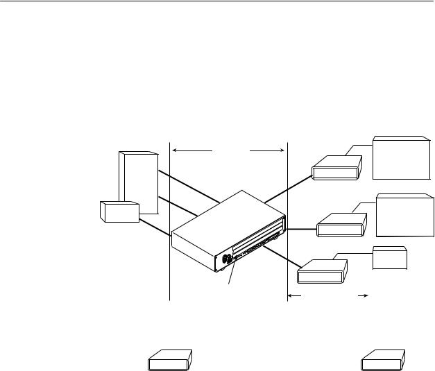
Figure 1-1 shows a network application using a 4-port Hotwire 8775 M/SDSL Termination Unit for access concentration in a central office (CO). A frame relay switch and a router are connected, through the termination unit, to partner units supporting a host or router, and frame relay encapsulated or unframed data.
|
|
|
V.35 |
E1 Host |
|
CO Site |
|
|
|
|
|
|
(Frame Relay |
|
Frame |
|
|
7975 |
|
|
|
Encapsulated |
||
Relay |
|
|
|
Data) |
Switch |
V.35 |
|
|
|
|
|
|
|
|
|
V.35 |
2.048 Mb |
V.35 |
Router |
|
|
|
||
Router |
|
over |
7975 |
(Frame Relay |
|
|
SDSL |
Encapsulated |
|
V.35 |
|
|
|
Data) |
|
|
|
|
|
|
|
|
V.35 |
|
|
|
7975 |
Router |
|
|
|
|
||
|
8775 Termination Unit |
Customer |
|
|
|
in 8600 DSLAM |
Premises (CP) |
|
|
|
CO Site |
|
|
Customer |
|
|
|
Premises |
|
|
LTU |
|
|
NTU |
7975 

 7975
7975
V.35 |
V.35 |
98-15938
Figure 1-1. Sample M/SDSL Configurations
User Interface Types
There are three types of user interfaces to the 7975 Standalone Termination Unit:
HMenu-driven async terminal interface screens. See Chapter 2, Using the Asynchronous Terminal Interface.
HFront panel LED status indicators. See Chapter 4, Monitoring the Unit.
HInternal DIP Switches. See Chapter 3, Initial Startup and Configuration.
7975-A2-GB20-40 |
December 1998 |
1-3 |
About the Hotwire 7975 Standalone Termination Unit
Front Panel LED Status Indicators
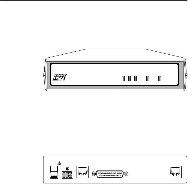
Figure 1-2 shows the front panel of the 7975 Standalone Termination Unit. For more information on front panel LEDs, refer to Chapter 4, Monitoring the Unit.
TM
POWERALARM TEST |
DSL |
DTE |
TM 7975 M/SDSL
98-15856
Figure 1-2. Hotwire 7975 Standalone Termination Unit Front Panel
Rear Panel Interface Connections
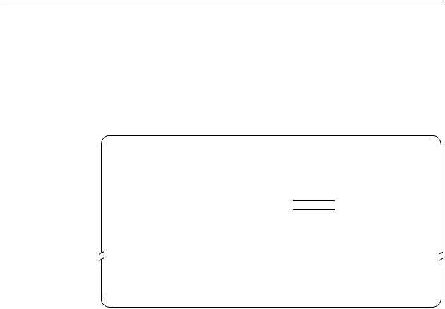
Figure 1-3 shows the physical interfaces of the 7975 Standalone Termination
Unit.
POWER |
COM |
DSL |
I |
|
PORT |
|
|
|
O |
|
|
98-15880
Figure 1-3. Hotwire 7975 Standalone Termination Unit Rear Panel
1-4 |
December 1998 |
7975-A2-GB20-40 |
About the Hotwire 7975 Standalone Termination Unit
SNMP Management Capabilities
The termination unit supports SNMP Version 1, and can be managed by any industry-standard SNMP manager and accessed using SNMP by external SNMP managers.
Management Information Base (MIB) Support
For a detailed description of supported MIBs, visit Paradyne's web site at
http://www.paradyne.com. The following MIBs are supported:
HMIB II (RFC 1213 and RFC 1573) ± Defines the general objects for use with a network management protocol in TCP/IP internets and provides general information about the unit. MIB II is backward-compatible with MIB I.
HRS-232-Like MIB (RFC 1659) ± Defines objects for managing RS-232-type interfaces (e.g., V.35, RS-422, RS-423, etc.) and supports the synchronous data port on the DSU.
HEnterprise MIB ± Supports configuration, status, statistics, and tests.
SNMP Traps Support
The 7975 Standalone Termination Unit supports traps as defined in
RFC 1215. They may include variable-bindings specified in the following MIBs:
HMIB II (RFC 1573) ± Defines the general objects for use with a network management protocol in TCP/IP internets and provides general information about the 7975 Standalone Termination Unit. MIB II is backward-compatible with MIB I.
HEnterprise MIB ± Supports configuration, status, statistics, and tests.
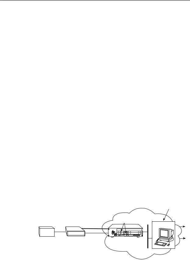
Figure 1-4 illustrates a typical M/SDSL SNMP configuration. Refer to Chapter 8,
IP Addressing and Appendix B, Standards Compliance for SNMP Traps.
|
|
|
|
|
Operation, Maintenance |
|
|
|
|
|
|
and Provisioning Center |
|
|
|
|
|
Network |
|
|
|
|
|
8775 |
|
SNMP NMS |
|
|
SDSL |
|
|
|
Data |
|
V.35 |
|
|
|
|
||
|
AC |
|
|
|
|
|
Router |
|
T5A |
|
|
|
|
|
EOC |
250V |
|
|
|
|
|
AC |
. |
|
|
|
|
|
|
INPUT |
. .. |
|
|
Voice |
7975 |
|
8600 |
|
Ethernet |
|
|
|
|
DSLAM |
Interface |
|
|
|
|
|
|
|
Ethernet |
|
|
|
|
|
|
LAN |
|
|
|
|
|
|
|
|
98-15858 |
Figure 1-4. M/SDSL SNMP Configuration
7975-A2-GB20-40 |
December 1998 |
1-5 |

About the Hotwire 7975 Standalone Termination Unit
1-6 |
December 1998 |
7975-A2-GB20-40 |

Using the Asynchronous Terminal
Interface
2
User Interface Access
You can communicate with the Hotwire 7975 Standalone Termination Unit with an asynchronous terminal interface (ATI) using one of the following methods:
HDirect connection through the COM port.
HUsing an external modem through the COM port.
HTelnet session through the Embedded Operations Channel (EOC).
NOTE:
Only one asynchronous terminal interface session can be active at a time, and another user's session cannot be forced to end. To automatically log out a user due to inactivity, enable the Inactivity Timeout option (see Table A-5, Telnet Sessions Options, in Appendix A, Configuration Option Tables).
Security can limit ATI access several ways. To limit user access or set up login
IDs, refer to Chapter 7, Security.
Communication Port Settings
Ensure that the device you connect communicates using these settings:
HData rate set to 9.6 kbps.
HCharacter length set to 8.
HParity set to None.
HStop Bits set to 1.
7975-A2-GB20-40 |
December 1998 |
2-1 |
Using the Asynchronous Terminal Interface
Initiating an ATI Session
The Main Menu screen is displayed on the screen unless a login ID and password is required or the ATI is already in use.
If security is enabled on the 7975 Standalone Termination Unit and you used Telnet to access it directly (you did not log in through the MCC), the system prompts you for a login ID and password
Login |
Hotwire |
|
Model: 7975 |
LOGIN
Login ID:
Enter Password:
±±±±±±±±±±±±±±±±±±±±±±±±±±±±±±±±±±±±±±±±±±±±±±±±±±±È±±±±±±±±±±±±±±±±±±±±±±±±±±±±±
Ctrl-a to access these functions Exit
After you enter a valid login ID and password, the Main Menu appears. If you enter an invalid login ID and password after three attempts, the Telnet session closes or the terminal connection returns to an idle state. Refer to Chapter 7,
Security.
If the ATI is already in use, you will see a connection refused or connection failed message (if you are using a Telnet session), or you will see the IP address of the other user (if you are using the Management Serial port).
2-2 |
December 1998 |
7975-A2-GB20-40 |
Using the Asynchronous Terminal Interface
main |
Access Level: Administrator |
Hotwire |
|
|
Model 7975 |
|
MAIN MENU |
|
|
Status |
|
|
Test |
|
Screen |
Configuration |
|
Area |
Control |
|
|
|
Screen
Function
Keys
Area
±±±±±±±±±±±±±±±±±±±±±±±±±±±±±±±±±±±±±±±±±±±±±±±±±±±È±±±±±±±±±±±±±±±±±±±±±±±±±±±±±
Ctrl-a to access these functions Exit
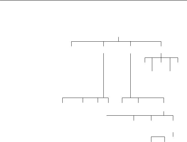
Entry to all of the termination unit's tasks begins at the Main Menu screen. The four branches of the Main menu are as follows:
Select . . . |
To . . . |
|
|
Status |
View system status, diagnostic test results, statistics, LEDs, and device |
|
identity information. |
|
|
Test |
Select and cancel tests for the termination unit's interfaces. |
|
|
Configuration |
Display and edit the configuration options. |
|
|
Control |
Change the device identity, administer logins, download new firmware, or |
|
initiate a power-up reset of the termination unit. |
|
|
After selecting an option, what appears on the screens depends on the:
HCurrent configuration ± How your termination unit is currently configured.
HEffective security access level ± An access level that is typically set by the system administrator for each interface and each user.
HData selection criteria ± What you entered in previous screens.
7975-A2-GB20-40 |
December 1998 |
2-3 |
Using the Asynchronous Terminal Interface
The following illustration shows the paths to the different ATI screens.
|
|
|
|
|
|
|
|
|
|
|
|
|
|
Main |
|
|
|
|
|
|
|
|
|
|
|
|
|
|
||
|
|
|
|
|
|
|
|
|
|
|
|
|
|
|
|
|
|
|
|
|
|
|
|
|
|
|
|
|||
|
|
|
|
|
|
|
|
|
|
|
|
|
|
|
|
|
|
|
|
|
|
|
|
|
|
|
||||
|
|
|
|
Status |
|
|
|
|
Test |
|
|
|
Configuration |
|
|
Control |
|
|
|
|
|
|
||||||||
|
|
|
|
|
|
|
|
|
|
|
|
|
|
|
|
|
|
|
|
|
|
|
|
|
|
|
|
|||
|
|
|
|
|
|
|
|
|
|
|
|
|
|
|
|
|
|
|
|
|
|
|
||||||||
|
|
|
|
|
|
|
|
|
|
|
|
|
|
|
|
|
|
|
|
|
|
|
||||||||
System and |
Performance |
Display Identity |
|
|
|
|
|
|
|
|
|
Change |
Download |
Reset |
|
|||||||||||||||
Test Status |
Statistics |
LEDs |
|
|
|
|
|
|
|
|
|
|
|
|
Identity |
Code |
AutoRate |
|
||||||||||||
|
|
|
|
|
|
|
|
|
|
|
|
|
|
|
|
|
|
|
|
|
Administer |
|
Apply |
|
|
|
||||
|
|
|
|
|
|
|
|
|
|
|
|
|
|
|
|
|
|
|
|
|
|
|
Reset |
|||||||
|
|
|
|
|
|
|
|
|
|
|
|
|
|
|
|
|
|
|
|
|
Logins |
Download |
Device |
|||||||
|
Network |
|
Network |
|
|
|
|
|
|
|
|
|
|
|
|
|
|
|
|
|
|
|
|
|
|
|
||||
|
Error |
Performance |
|
|
|
|
|
|
|
|
|
|
|
|
|
|
|
|
|
|
|
|
|
|
|
|||||
|
Statistics |
|
Statistics |
|
|
|
|
|
|
|
|
|
|
|
|
|
|
|
|
|
|
|
|
|
|
|
||||
|
Network Tests |
SYNC Data |
Device |
Abort |
Factory |
Configuration Current Configuration |
|
|
|
|||||||||||||||||||||
|
|
|
|
|
Port Tests |
Tests |
|
All |
Config |
|
Loader |
Edit/Display |
|
|
|
|||||||||||||||
|
|
|
|
|
|
|
|
|
|
|
Tests |
|
|
|
|
|
|
|
|
|
|
|
|
|
|
|
|
|
||
|
|
|
|
|
|
|
|
|
|
|
|
|
|
|
|
|
|
|||||||||||||
|
|
|
|
|
|
|
|
|
|
|
|
|
|
|
|
|
|
|
|
|
|
|
|
|
|
|
|
|||
|
|
|
|
|
|
|
|
|
|
|
System |
|
Communication Management |
|||||||||||||||||
|
|
|
|
|
|
|
|
|
|
Network |
Sync |
|
||||||||||||||||||
|
|
|
|
|
|
|
|
|
|
|
|
|
|
Port |
Options |
|
Port |
|
|
|
|
and |
|
|
|
|||||
|
|
|
|
|
|
|
|
|
|
|
|
|
|
|
|
|
|
|
|
|
|
|
Communication |
|||||||
|
|
|
|
|
|
|
|
|
|
|
|
|
|
|
|
|
|
|
|
|
|
|
|
|
|
|||||
|
|
|
|
|
|
|
|
|
|
|
|
|
|
|
|
|
|
|
|
|
|
|
|
|
||||||
|
|
|
|
|
|
|
|
|
|
|
|
|
|
|
|
|
|
|
|
|
Telnet |
SNMP |
Communication |
|||||||
|
|
|
|
|
|
|
|
|
|
|
|
|
|
|
|
|
|
|
|
|
Session |
Traps |
Protocol Option |
|||||||
|
|
|
|
|
|
|
|
|
|
|
|
|
|
|
|
|
|
|
|
|
|
|
|
|
|
|
|
98-15859 |
||
2-4 |
December 1998 |
7975-A2-GB20-40 |
Using the Asynchronous Terminal Interface
Screen Work Areas
There are two user work areas:
HScreen area ± This is the area above the dotted line that provides the menu path, menus, and input fields.
The menu path appears as the first line on the screen. In this manual, the menu path is presented as a menu selection sequence with the names of the screens:
Main Menu → Configuration → Load Configuration From → Network
Interface Options
HScreen function key area ± This is the area below the dotted line that lists function keys specific to the screen, field value choices, and system messages.
Menu Path
|
main/config/network |
Hotwire |
|
|
Model: 7975 |
|
NETWORK INTERFACE OPTIONS |
|
|
Margin Threshold: |
±3db |
|
Excessive Error Rate Threshold: 1E±5 |
|
|
AutoRate: |
Enable |
Input |
Peer IP Address: |
111.255.255.000 Clear |
|
|
|
Fields
|
Circuit Identifier: |
|
|
Clear |
|
±±±±±±±±±±±±±±±±±±±±±±±±±±±±±±±±±±±±±±±±±±±±±±±±±±±È±±±±±±±±±±±±±±±±±±±±±±±±±±±±± |
|||
Screen |
Ctrl-a to access these functions, ESC for previous menu |
MainMenu Exit |
||
Function |
Save |
|
|
|
Keys |
Select: 1E±4, 1E±5, 1E±6, 1E±7, 1E±8, 1E±9 |
LOS at Net, Pt n |
||
|
|
|
|
|
Field Value |
|
System |
|
|
Choices |
|
Messages |
|
|
7975-A2-GB20-40 |
December 1998 |
2-5 |

Using the Asynchronous Terminal Interface
Navigating the Screens
You can navigate the screens by:
HUsing keyboard keys
HUsing screen function keys
HSwitching between the two screen work areas
Keyboard Keys
Use the following keyboard keys to navigate within the screen.
Press . . . |
To . . . |
|
|
Ctrl-a |
Move cursor between the screen area and the screen function |
|
keys area below the dotted line at the bottom of the screen. |
|
|
Esc |
Return to the previous screen. |
|
|
Tab |
Move cursor to the next field on the screen. |
|
|
Backspace |
Move cursor to the previous field on the screen. |
|
|
Return (Enter) |
Accept entry or display valid options on the last row of the screen |
|
when pressed before entering data or after entering invalid data. |
|
|
Ctrl-k |
Tab backwards (move cursor one field to the left). |
|
|
Spacebar |
Select the next valid value for the field. |
|
|
Delete (Del) |
Delete character that the cursor is on. |
|
|
Up Arrow or Ctrl-u |
Move cursor up one field within a column on the same screen. |
|
|
Down Arrow or Ctrl-d |
Move cursor down one field within a column on the same screen. |
|
|
Right Arrow or Ctrl-f |
Move cursor one character to the right if in edit mode. |
|
|
Left Arrow or Ctrl-b |
Move cursor one character to the left if in edit mode. |
|
|
Ctrl-l |
Redraw the screen display, clearing information typed in but not |
|
yet entered. |
|
|
"Procedure
To make a menu or field selection:
1.Press the Tab key or the right arrow key to position the cursor on a menu or field selection. Each selection is highlighted as you press the key to move the cursor from position to position.
2.Press Enter.
The selected menu or screen appears.
3.Continue Steps 1 and 2 until you reach the screen you want.
2-6 |
December 1998 |
7975-A2-GB20-40 |

Using the Asynchronous Terminal Interface
The current setting or value appears to the right of the field name. You can enter information into a selected field by:
HTyping in the first letter(s) of a field value or command.
HSwitching from the screen area to the screen function area below the dotted line and selecting or entering the designated screen function key.
If a field is blank and the Field Values screen area displays valid selections, press the spacebar and the first valid value for the field will appear. Continue pressing the spacebar to scroll through other valid values.
Screen Function Keys
All screen function keys located below the dotted line operate the same way (upperor lowercase) throughout the screens.
For the screen |
Select . . . |
And press Enter to . . . |
function . . . |
||
|
|
|
ClrFar |
F or f |
Clear far-end network statistics and refresh the screen. |
|
|
|
ClrNear |
N or n |
Clear near-end network statistics and refresh the screen. |
|
|
|
Delete |
L or l |
Delete data. |
|
|
|
Exit |
E or e |
Terminate the async terminal session. |
|
|
|
MainMenu |
M or m |
Return to the Main Menu screen. |
|
|
|
New |
N or n |
Enter new data. |
|
|
|
PgDn |
D or d |
Display the next page, or group of entries. |
|
|
|
PgUp |
U or u |
Display the previous page, or group of entries. |
|
|
|
ResetMon |
R or r |
Reset an active Monitor 511 test counter to zero. |
|
|
|
Save |
S or s |
Save information. |
|
|
|
7975-A2-GB20-40 |
December 1998 |
2-7 |

Using the Asynchronous Terminal Interface
Switching Between Screen Work Areas
Select Ctrl-a to switch between the two screen work areas to perform all screen functions.
"Procedure
To access the screen function area below the dotted line:
1.Press Ctrl-a to switch from the screen area to the screen function key area below the dotted line.
2.Select either the function's designated (underlined) character or press the Tab key until you reach the desired function key.
Example:
To save the current screen, type s or S (Save).
3.Press Enter.
4.To return to the screen area above the dotted line, press Ctrl-a again
main/config/network |
|
Hotwire |
|
|
|
Model: 7975 |
|
|
NETWORK INTERFACE OPTIONS |
|
|
Margin Threshold: |
±3db |
||
Excessive Error Rate Threshold: 1E±5 |
|||
AutoRate |
Disable |
||
DSL Line rate |
144 |
|
|
Peer IP Address: |
111.255.255.000 Clear |
||
Circuit Identifier: |
|
|
Clear |
±±±±±±±±±±±±±±±±±±±±±±±±±±±±±±±±±±±±±±±±±±±±±±±±±±±È±±±±±±±±±±±±±±±±±±±±±±±±±±±±±
Ctrl-a to access these functions, ESC for previous menu |
MainMenu Exit |
Save |
|
2-8 |
December 1998 |
7975-A2-GB20-40 |

Using the Asynchronous Terminal Interface
Ending an ATI Session
Use the Exit function key from any screen to terminate the session.
"Procedure
To end a session with the asynchronous terminal interface:
1.Press Ctrl-a to go to the screen function key area below the dotted line.
2.Save changes if required. A confirmation message appears if you have made but not saved changes to your configuration.
3.Tab to Exit (or type e or E) and press Enter.
7975-A2-GB20-40 |
December 1998 |
2-9 |

Using the Asynchronous Terminal Interface
2-10 |
December 1998 |
7975-A2-GB20-40 |

Initial Startup and Configuration
3
Overview
This chapter provides instructions on how to access and configure your unit for the first time. This chapter includes procedures for:
HConnecting power to the unit.
HConnecting the unit to the network.
HConnecting a system terminal.
HProviding initial unit identity information or changing existing identity information.
HConfiguring your unit using internal switchpacks or using the Configuration Edit menus.
HChoosing the current or factory default configuration options or downloading configuration options from a TFTP server.
HModifying current configuration options using the Configuration Edit/Display menu.
HSaving your changes.
HDownloading unit firmware from a TFTP server.
7975-A2-GB20-40 |
December 1998 |
3-1 |

Initial Startup and Configuration
Connecting Power to the Unit
If your package includes a power pack: Plug the power pack into an ac outlet having a nominal voltage rating between 100±240 Vac. Connect the output cable of the power pack to the connector marked POWER on the rear panel.
If your package includes a direct-connection dc power cable: Connect the unit to an external dc power source as described in Connecting the Unit to an Optional External DC Power Source.
Connecting the Unit to an Optional External DC Power Source
Use the following procedures only if you want to use the dc power cable.
Using the dc power cable, the Hotwire 7975 Standalone Termination Unit is capable of operating on a +24 Vdc power supply.
"Procedure
To use the dc power cable:
1.Connect the green wire to a suitable earth ground.
2.Connect the orange wire to the +24 Vdc source.
3.Connect the white wire to the return.
4.Cut the black, red, and blue wires off at the outer insulation.
5.Plug the power connector into the 7975 Standalone Termination Unit.
|
|
Black |
X |
|
1 |
||
|
|
||
|
Red |
||
|
2 |
X |
|
|
|
||
|
Green |
||
|
3 |
Earth Ground |
|
|
|
||
|
White |
||
|
4 |
RTN |
|
|
|
||
|
Orange |
||
|
5 |
+24 Vdc |
|
|
|
||
|
Blue |
||
|
6 |
X |
|
|
|
||
|
|
|
|
|
|
|
|
98-14158-01
+24 Vdc Power Supply Pinouts
3-2 |
December 1998 |
7975-A2-GB20-40 |

Initial Startup and Configuration
Connecting to the Network
"Procedure
To connect your unit to the network:
1.Connect one end of the network cable into the rear panel DSL jack. Connect the other end to your DSL network interface.
NOTE:
Do not use a flat VF network cable as this may severely degrade the performance of the termination unit. Use only Cat 5 twisted-pair network cable.
Connecting to a System Terminal
An optional system maintenance terminal may be attached to your Hotwire 7975 Standalone Termination Unit through the modular jack on the rear panel. You may have terminals attached to both endpoints. The system terminal must be a VT100-compatible terminal or a PC running terminal emulation software.
The system maintenance terminal allows you to view the status of the unit, and change configuration options.
Connect the 9-pin end of the terminal cable into a COM port on your PC. Plug the other end into the modular jack on the rear panel. If your PC requires a 25-pin connector to the COM port, see Appendix C, Cables and Pin Assignments, for the correct cable pinouts.
Make sure the communication parameters on your PC or terminal are set to:
H9600 baud
H8 bit characters
Hno parity
H1 stop bit
Hno flow control
Press Enter from your terminal or PC to activate the Main Menu for the attached unit. The system runs diagnostics and status checks. After a few moments, the Main Menu or Logon screen appears on your terminal.
7975-A2-GB20-40 |
December 1998 |
3-3 |

Initial Startup and Configuration
Entering Identity Information
After accessing your unit for the first time, use the Change Identity screen to determine SNMP administrative system information that will be displayed on the Identity screen of the Status branch. To access the Card Identity screen, follow this menu selection sequence:
Main Menu → Control → Change
main/control/change_identity |
Hotwire |
|||
|
|
|
|
Model: 7975 |
|
|
IDENTITY |
|
|
System Name: |
lllQJ98-001 |
Clear |
||
|
|
|
|
|
System Location: Bldg. A412, 2nd Floor, Left cabinet |
|
Clear |
||
System Contact: |
C. Parker 800-727-2396 pager 888-555-1212 |
Clear |
||
±±±±±±±±±±±±±±±±±±±±±±±±±±±±±±±±±±±±±±±±±±±±±±±±±±±È±±±±±±±±±±±±±±±±±±±±±±±±±±±±±
Ctrl-a to access these functions, ESC for previous menu |
MainMenu Exit |
Save |
|
The three System entry fields are alphanumeric and provide 128 characters for each field. The System entries appear on the Identity display as shown above. The SNMP System entry fields are:
HSystem Name: The general SNMP system name.
HSystem Location: The physical location of the SNMP-managed device.
HSystem Contact: Identification information, such as contact name, phone number, or mailing address.
Valid entry values are any printable ASCII character. ASCII printable characters include:
HNumeric 0±9
HUpper or lower case A±Z
HSpace
HAll ASCII symbols except the caret (^)
Select Clear to reset a field to a null value.
3-4 |
December 1998 |
7975-A2-GB20-40 |
Loading...