


 Loading...
You have accessed an older version of a Paradyne product document.
Paradyne is no longer a subsidiary of AT&T. Any reference to AT&T Paradyne is amended to read Paradyne Corporation.

COMSPHERE
3000 Series Carrier
Installation Manual
Document No. 3000-A2-GA31-80


 Paradyne
Printed on recycled paper
December 1994

COMSPHERE 3000 Series Carrier
COMSPHERE
3000 Series Carrier
Installation Manual
3000-A2-GA31-80
9th Edition (December 1994)
Changes and enhancements to the product and to the information herein will be documented and issued as a new release.
A customer opinion card is provided at the front of this publication and your comments are appreciated. If the form has been removed, address comments to AT&T Paradyne Corporation, Technical Publications, 8545 126th Ave. N., P.O. Box 2826, Largo, Florida, 34649-2826. AT&T Paradyne may use or distribute any of the information supplied, as appropriate, without incurring any obligation whatsoever.
ACCULINK is a registered trademark of AT&T.
ACCUNET is a registered trademark of AT&T.
ANALYSIS is a trademark of AT&T.
AT is a trademark of Hayes Microcomputer Products, Inc.
COMSPHERE is a registered trademark of AT&T.
DATAPHONE is a registered trademark of AT&T.
Dataroute is a registered trademark of Bell Canada.
MCI is a registered trademark of MCI Communications, Inc.
Microsoft is a registered trademark of Microsoft Corporation.
US SPRINT is a registered trademark of US SPRINT Communications Company.
Windows is a trademark of Microsoft Corporation.
COPYRIGHT E 1994 AT&T Paradyne Corporation. All rights reserved.
This publication is protected by federal copyright law. No part of this publication may be copied or distributed, transmitted, transcribed, stored in a retrieval system, or translated into any human or computer language in any form or by any means, electronic, mechanical, magnetic, manual or otherwise, or disclosed to third parties without the express written permission of AT&T Paradyne Corporation, 8545 126th Avenue North, P.O. Box 2826, Largo, Florida 34649-2826.
AT&T Paradyne Corporation makes no representation or warranties with respect to the contents hereof and specifically disclaims any implied warranties of merchantability or fitness for a particular purpose. Further, AT&T Paradyne Corporation reserves the right to revise this publication and to make changes from time to time in the contents hereof without obligation of AT&T Paradyne Corporation to notify any person of such revision or changes.
A |
December 1994 |
3000-A2-GA31-80 |

Safety Instructions
Important Safety Instructions
1.Read and follow all warning notices and instructions marked on the product or included in the manual.
2.This product is intended to be used with a three-wire grounding type plug - a plug which has a grounding pin. This is a safety feature. Equipment grounding is vital to ensure safe operation. Do not defeat the purpose of the grounding type plug by modifying the plug or using an adaptor.
Prior to installation, use an outlet tester or a voltmeter to check the ac receptacle for the presence of earth ground. If the receptacle is not properly grounded, the installation must not continue until a qualified electrician has corrected the problem.
If a three-wire grounding type power source is not available, consult a qualified electrician to determine another method of grounding the equipment.
The dc configuration of this product is to be grounded by connecting an external wire between the building ground and the equipment ground screw on the rear of the power supply assembly. Consult a qualified electrician to ensure that the ground connections are connected.
3.Slots and openings in the cabinet are provided for ventilation. To ensure reliable operation of the product and to protect it from overheating, these slots and openings must not be blocked or covered.
4.Do not allow anything to rest on the power cord and do not locate the product where persons will walk on the power cord.
5.Do not attempt to service this product yourself, as opening or removing covers may expose you to dangerous high voltage points or other risks. Refer all servicing to qualified service personnel.
6.General purpose cables are provided with this product. Special cables, which may be required by the regulatory inspection authority for the installation site, are the responsibility of the customer.
7.When installed in the final configuration, the product must comply with the applicable Safety Standards and regulatory requirements of the country in which it is installed. If necessary, consult with the appropriate regulatory agencies and inspection authorities to ensure compliance.
8.A rare phenomenon can create a voltage potential between the earth grounds of two or more buildings. If products installed in separate buildings are interconnected, the voltage potential may cause a hazardous condition. Consult a qualified electrical consultant to determine whether or not this phenomenon exists and, if necessary, implement corrective action prior to interconnecting the products.
In addition, if the equipment is to be used with telecommunications circuits, take the following precautions:
±Never install telephone wiring during a lightning storm.
±Never install telephone jacks in wet locations unless the jack is specifically designed for wet locations.
±Never touch uninsulated telephone wires or terminals unless the telephone line has been disconnected at the network interface.
±Use caution when installing or modifying telephone lines.
±Avoid using a telephone (other than a cordless type) during an electrical storm. There may be a remote risk of electric shock from lightning.
±Do not use the telephone to report a gas leak in the vicinity of the leak.
3000-A2-GA31-80 |
December 1994 |
B |

COMSPHERE 3000 Series Carrier
Notices
|
|
|
|
WARNING |
|
THIS EQUIPMENT HAS BEEN TESTED AND FOUND TO COMPLY WITH THE LIMITS FOR A CLASS A |
DIGITAL DEVICE, |
||||
PURSUANT |
TO |
PART |
15 OF THE FCC RULES. THESE LIMITS ARE DESIGNED TO PROVIDE |
REASONABLE |
|
PROTECTION AGAINST HARMFUL INTERFERENCE WHEN THE EQUIPMENT IS OPERATED IN A COMMERCIAL |
|||||
ENVIRONMENT. THIS EQUIPMENT GENERATES, USES, AND CAN RADIATE RADIO FREQUENCY ENERGY AND, IF NOT |
|||||
INSTALLED |
AND |
USED |
IN ACCORDANCE WITH THE INSTRUCTION MANUAL, MAY CAUSE HARMFUL INTERFERENCE |
||
TO RADIO COMMUNICATIONS. OPERATION OF THIS EQUIPMENT IN A RESIDENTIAL AREA IS LIKELY TO CAUSE |
|||||
HARMFUL |
INTERFERENCE IN WHICH CASE THE USER WILL BE REQUIRED TO CORRECT THE INTERFERENCE AT |
||||
HIS |
OWN |
EXPENSE. |
|
|
|
THE |
AUTHORITY |
TO |
OPERATE THIS EQUIPMENT IS CONDITIONED BY THE REQUIREMENTS THAT NO |
||
MODIFICATIONS WILL BE MADE TO THE EQUIPMENT UNLESS THE CHANGES OR MODIFICATIONS ARE EXPRESSLY |
|||||
APPROVED |
BY AT&T |
PARADYNE. |
|||
|
|
|
|
|
|
WARNING
TO USERS OF DIGITAL APPARATUS IN CANADA:
THE DIGITAL APPARATUS DOES NOT EXCEED THE CLASS A LIMITS FOR RADIO NOISE EMISSIONS FROM DIGITAL APPARATUS SET OUT IN THE RADIO INTERFERENCE REGULATIONS OF THE CANADIAN DEPARTMENT OF COMMUNICATIONS.
LE PRESÉNT APPAREIL NUMÉRIQUE N'ÉMET PAS DE BRUITS RADIOÉLECTRIQUES DÉPASSANT LES LIMITES APPLICABLES AUX APPAREILS NUMÉRIQUES DE LA CLASSE A PRESCRITES DANS LE RÈGLEMENT SUR LE BROUILLAGE RADIOÉLECTRIQUE ÉDICTÉ PAR LE MINISTÈRE DES COMMUNICATIONS DU CANADA.
C |
December 1994 |
3000-A2-GA31-80 |

Table of Contents
Preface
Objectives and Reader Assumptions . . . . . . . . . . . . . . . . . . . . . . . . . . . vii Abstract . . . . . . . . . . . . . . . . . . . . . . . . . . . . . . . . . . . . . . . . . . . . . . . . . vii Related Documents . . . . . . . . . . . . . . . . . . . . . . . . . . . . . . . . . . . . . . . . vii
1. Introduction
Overview . . . . . . . . . . . . . . . . . . . . . . . . . . . . . . . . . . . . . . . . . . . . . . . . 1-1
Features . . . . . . . . . . . . . . . . . . . . . . . . . . . . . . . . . . . . . . . . . . . . . . . . . 1-1
Technical Specifications . . . . . . . . . . . . . . . . . . . . . . . . . . . . . . . . . . . . 1-3
Equipment Warranty and Support . . . . . . . . . . . . . . . . . . . . . . . . . . . . . 1-8
2. Installation Planning
Overview . . . . . . . . . . . . . . . . . . . . . . . . . . . . . . . . . . . . . . . . . . . . . . . . 2-1
Customer Responsibilities . . . . . . . . . . . . . . . . . . . . . . . . . . . . . . . . . . . 2-2
Installation Considerations . . . . . . . . . . . . . . . . . . . . . . . . . . . . . . . . . . . 2-2
3. Installation
Overview . . . . . . . . . . . . . . . . . . . . . . . . . . . . . . . . . . . . . . . . . . . . . . . . 3-2 Cabinet Unpacking and Setup . . . . . . . . . . . . . . . . . . . . . . . . . . . . . . . . 3-4 Carrier Installation . . . . . . . . . . . . . . . . . . . . . . . . . . . . . . . . . . . . . . . . . 3-5 Power Transformer Unit Installation . . . . . . . . . . . . . . . . . . . . . . . . . . . 3-10 Fan Module Installation . . . . . . . . . . . . . . . . . . . . . . . . . . . . . . . . . . . . . 3-15 Shared Diagnostic Control Panel (SDCP) Installation . . . . . . . . . . . . . 3-17 Speaker Panel Installation . . . . . . . . . . . . . . . . . . . . . . . . . . . . . . . . . . . 3-19 Shared Diagnostic Unit (SDU) Installation . . . . . . . . . . . . . . . . . . . . . . 3-22 Auxiliary Backplane Installation . . . . . . . . . . . . . . . . . . . . . . . . . . . . . . 3-32 Network Interface Installation . . . . . . . . . . . . . . . . . . . . . . . . . . . . . . . . 3-37 Circuit Card Installation . . . . . . . . . . . . . . . . . . . . . . . . . . . . . . . . . . . . . 3-47
3000-A2-GA31-80 |
December 1994 |
i |

COMSPHERE 3000 Series Carrier
Appendices
A. COMSPHERE Interface Connections . . . . . . . . . . . . . . . . . . . . . . A-1 B. Models 3151/3161 Interface Connections . . . . . . . . . . . . . . . . . . . B-1 C. Equipment List . . . . . . . . . . . . . . . . . . . . . . . . . . . . . . . . . . . . . . . . C-1
Glossary
Index
ii |
December 1994 |
3000-A2-GA31-80 |

Table of Contents
List of Figures
Figure |
Page |
|
1-1 |
COMSPHERE 3000 Series Carrier . . . . . . . . . . . . . . . . . . . . . . . . . . . . . . . . . . . . |
. . 1-2 |
3-1 |
COMSPHERE 3000 Series Carrier Assembly . . . . . . . . . . . . . . . . . . . . . . . . . . . |
. . 3-2 |
3-2 |
COMSPHERE 3000 Series Carrier Mounting Brackets . . . . . . . . . . . . . . . . . . . . |
. . 3-6 |
3-3 |
Installation of First Carrier into Cabinet with Threaded Screw Holes . . . . . . . . . |
. . 3-7 |
3-4 |
Installation of First Carrier into Cabinet with No Threaded Screw Holes . . . . . . |
. . 3-8 |
3-5 |
72-Inch Cabinet Fully Configured with Six COMSPHERE 3000 Series Carriers |
. . 3-9 |
3-6 |
Power Transformer Unit Installation . . . . . . . . . . . . . . . . . . . . . . . . . . . . . . . . . . . |
. . 3-10 |
3-7 |
COMSPHERE 3000 Series Carrier (Rear) . . . . . . . . . . . . . . . . . . . . . . . . . . . . . . |
. . 3-11 |
3-8 |
Alarm Output or Ground Strap Terminal Installation . . . . . . . . . . . . . . . . . . . . . . |
. . 3-13 |
3-9 |
Alarm Output Contacts . . . . . . . . . . . . . . . . . . . . . . . . . . . . . . . . . . . . . . . . . . . . . |
. . 3-14 |
3-10 |
Fan Module Installation . . . . . . . . . . . . . . . . . . . . . . . . . . . . . . . . . . . . . . . . . . . . . |
. . 3-16 |
3-11 |
Shared Diagnostic Control Panel . . . . . . . . . . . . . . . . . . . . . . . . . . . . . . . . . . . . . . |
. . 3-17 |
3-12 |
Shared Diagnostic Control Panel (SDCP) Installation . . . . . . . . . . . . . . . . . . . . . |
. . 3-18 |
3-13 |
Models 3811/3911 Speaker Panel Installation Directly to Cabinet Rails . . . . . . . |
. . 3-20 |
3-14 |
SDU Faceplate . . . . . . . . . . . . . . . . . . . . . . . . . . . . . . . . . . . . . . . . . . . . . . . . . . . . |
. . 3-22 |
3-15 |
Shared Diagnostic Unit Circuit Card, Rear View . . . . . . . . . . . . . . . . . . . . . . . . . |
. . 3-23 |
3-16 |
Circuit Pack Lock . . . . . . . . . . . . . . . . . . . . . . . . . . . . . . . . . . . . . . . . . . . . . . . . . |
. . 3-26 |
3-17 |
NMS to a COMSPHERE 3000 Series Carrier Connection . . . . . . . . . . . . . . . . . . |
. . 3-28 |
3-18 |
Daisy Chaining of Devices into a COMSPHERE 3000 Series Carrier . . . . . . . . . |
. . 3-29 |
3-19 |
Daisy Chaining of Devices from a COMSPHERE 3000 Series Carrier . . . . . . . . |
. . 3-30 |
3-20 |
NMS and Shared Diagnostic Control Panel Interface Connections . . . . . . . . . . . |
. . 3-31 |
3-21 |
Auxiliary Backplane Being Installed over Slots 9 ±16 of the |
|
|
COMSPHERE 3000 Series Carrier . . . . . . . . . . . . . . . . . . . . . . . . . . . . . . . . . . |
. . 3-32 |
3-22 |
COMSPHERE 3000 Series Carrier with Two Auxiliary Backplanes . . . . . . . . . . |
. . 3-33 |
3-23 |
T1 Network Cable Retainer . . . . . . . . . . . . . . . . . . . . . . . . . . . . . . . . . . . . . . . . . . |
. . 3-34 |
3-24 |
Auxiliary Backplane . . . . . . . . . . . . . . . . . . . . . . . . . . . . . . . . . . . . . . . . . . . . . . . |
. . 3-35 |
3-25 |
COM Port Adapter . . . . . . . . . . . . . . . . . . . . . . . . . . . . . . . . . . . . . . . . . . . . . . . . . |
. . 3-36 |
3-26 |
PC Attached to Auxiliary Backplane Using COM Port Adapter and Cable . . . . . |
. . 3-36 |
3-27 |
Network Interface Cable Installation . . . . . . . . . . . . . . . . . . . . . . . . . . . . . . . . . . . |
. . 3-37 |
3-28 |
Dial/Lease Modem Interconnection Schemes . . . . . . . . . . . . . . . . . . . . . . . . . . . . |
. . 3-39 |
3-29 |
DSU, DBM, or DSU with V.32 or 2-Wire Switched 56 DBM |
|
|
Interconnection Schemes . . . . . . . . . . . . . . . . . . . . . . . . . . . . . . . . . . . . . . . . . . |
. . 3-40 |
3-30 |
DSU with 4-Wire Switched 56 DBM Interconnection Schemes . . . . . . . . . . . . . . |
. . 3-41 |
3-31 |
Network Interface Module . . . . . . . . . . . . . . . . . . . . . . . . . . . . . . . . . . . . . . . . . . . |
. . 3-44 |
3-32 |
Dial Network Interface Module Installation . . . . . . . . . . . . . . . . . . . . . . . . . . . . . |
. . 3-45 |
3-33 |
Network Interface for Models 3151 and 3161 Using an Auxiliary Backplane . . . |
. . 3-46 |
3-34 |
Modular DSU or Dial/Lease Modem, and Rear Connector Plate . . . . . . . . . . . . . |
. . 3-47 |
3-35 |
Modular DSU-TDM or DSU-MCMP and Connector Module . . . . . . . . . . . . . . . |
. . 3-48 |
3-36 |
Model 3151 and 3161 Circuit Cards . . . . . . . . . . . . . . . . . . . . . . . . . . . . . . . . . . . |
. . 3-49 |
3000-A2-GA31-80 |
December 1994 |
iii |

COMSPHERE 3000 Series Carrier
Figure |
Page |
|
3-37 |
Circuit Card Installation . . . . . . . . . . . . . . . . . . . . . . . . . . . . . . . . . . . . . . . . . . . . . . . |
3-51 |
3-38 |
Cabling and Ferrite Chokes . . . . . . . . . . . . . . . . . . . . . . . . . . . . . . . . . . . . . . . . . . . . |
3-52 |
A-1 |
50-Pin Cable Connector . . . . . . . . . . . . . . . . . . . . . . . . . . . . . . . . . . . . . . . . . . . . . . . |
A-1 |
A-2 |
50-Pin to Modular Plug Digital/Lease Conversion Cable . . . . . . . . . . . . . . . . . . . . |
A-4 |
A-3 |
Connectors on the COMSPHERE 3000 Series Carrier Backplane . . . . . . . . . . . . . . |
A-9 |
B-1 |
Auxiliary Backplane Connectors . . . . . . . . . . . . . . . . . . . . . . . . . . . . . . . . . . . . . . . . |
B-2 |
B-2 |
T1 Line Interface Multiplug Adapter with RJ48C Connector |
|
|
(Feature Number 3100-F1-930) . . . . . . . . . . . . . . . . . . . . . . . . . . . . . . . . . . . . . . . |
B-4 |
B-3 |
T1 Network Interface Multiport Adapter with 50-pin RJ48H to |
|
|
8-pin RJ48C Connectors (Feature Number 3100-F1-930) . . . . . . . . . . . . . . . . . . |
B-5 |
B-4 |
DTE (DSX-1) Cable . . . . . . . . . . . . . . . . . . . . . . . . . . . . . . . . . . . . . . . . . . . . . . . . . |
B-7 |
B-5 |
COM Port-to-PC Cable (Feature Number 3100-F1-550) . . . . . . . . . . . . . . . . . . . . . |
B-8 |
B-6 |
COM Port-to-PC Adapter (Feature Number 3100-F1-920) . . . . . . . . . . . . . . . . . . . |
B-9 |
B-7 |
COM Port Adapter . . . . . . . . . . . . . . . . . . . . . . . . . . . . . . . . . . . . . . . . . . . . . . . . . . . |
B-9 |
B-8 |
COM Port-to-Terminal/Printer Cable (Feature Number 3100-F1-540) . . . . . . . . . . |
B-10 |
B-9 |
EIA-530A to RS449 Adapter Cable (Feature Number 3100-F1-580) . . . . . . . . . . . . |
B-13 |
B-10 |
EIA-530A to V.35 Adapter Cable (Feature Number 3100-F1-570) . . . . . . . . . . . . . |
B-15 |
B-11 |
External Clock Connector . . . . . . . . . . . . . . . . . . . . . . . . . . . . . . . . . . . . . . . . . . . . . |
B-16 |
B-12 |
Diagnostic Channel Extension Cable Connectors . . . . . . . . . . . . . . . . . . . . . . . . . . . |
B-17 |
B-13 |
Diagnostic Channel Extension Cable (Feature Number 3100-F1-910) . . . . . . . . . . . |
B-17 |
iv |
December 1994 |
3000-A2-GA31-80 |

Table of Contents
List of Tables
Table |
|
Page |
1-1 |
Technical Specifications for the COMSPHERE 3000 Series Carrier . . . . . . . . . . . . |
1-3 |
3-1 |
Fan Module Cooling Requirements . . . . . . . . . . . . . . . . . . . . . . . . . . . . . . . . . . . . . . |
3-15 |
3-2 |
Shared Diagnostic Control Panel Status Indicators . . . . . . . . . . . . . . . . . . . . . . . . . . |
3-17 |
3-3 |
Shared Diagnostic Unit Status Indicators . . . . . . . . . . . . . . . . . . . . . . . . . . . . . . . . . |
3-23 |
3-4 |
Carrier Address DIP Switches . . . . . . . . . . . . . . . . . . . . . . . . . . . . . . . . . . . . . . . . . . |
3-24 |
3-5 |
Carrier Address Assignment . . . . . . . . . . . . . . . . . . . . . . . . . . . . . . . . . . . . . . . . . . . |
3-25 |
3-6 |
Protocol DIP Switches . . . . . . . . . . . . . . . . . . . . . . . . . . . . . . . . . . . . . . . . . . . . . . . . |
3-25 |
A-1 |
Digital or Analog Leased-Line Network Interface . . . . . . . . . . . . . . . . . . . . . . . . . . |
A-2 |
A-2 |
RJ21X (Permissive) Dial and 2-Wire Switched 56 Network Interface Module . . . . |
A-2 |
A-3 |
RJ27X (Programmable) Dial Network Interface Module . . . . . . . . . . . . . . . . . . . . . |
A-3 |
A-4 |
SJA57 4-Wire Switched 56 Network Interface Module . . . . . . . . . . . . . . . . . . . . . . |
A-3 |
A-5 |
SDU ± NMS Interface . . . . . . . . . . . . . . . . . . . . . . . . . . . . . . . . . . . . . . . . . . . . . . . . |
A-4 |
A-6 |
SDU ± Shared Diagnostic Control Panel Interface . . . . . . . . . . . . . . . . . . . . . . . . . . |
A-4 |
A-7 |
Pinout for 3600-F2-503 (Digital and JM8 Leased) Network Interface Cables . . . . . |
A-5 |
A-8 |
Pinout for 3600-F2-504 (Dial Programmable ± RJ45S) Network Interface Cable . . |
A-6 |
A-9 |
Pinout for 3600-F1-505 (Dial Permissive ± RJ11C) Network Interface Cable . . . . . |
A-7 |
A-10 |
Pinout for 3000-F1-009 (50-Pin to Eight 6-Pin Modular) Network |
|
|
Interface Cable . . . . . . . . . . . . . . . . . . . . . . . . . . . . . . . . . . . . . . . . . . . . . . . . . . . . |
A-8 |
A-11 |
Connectors on the COMSPHERE 3000 Series Carrier's Backplane . . . . . . . . . . . . . |
A-9 |
A-12 |
D-Lead Control Interface . . . . . . . . . . . . . . . . . . . . . . . . . . . . . . . . . . . . . . . . . . . . . . |
A-10 |
B-1 |
Auxiliary Backplane Connectors . . . . . . . . . . . . . . . . . . . . . . . . . . . . . . . . . . . . . . . . |
B-3 |
B-2 |
T1 Network Interface Connector (RJ48H) . . . . . . . . . . . . . . . . . . . . . . . . . . . . . . . . |
B-6 |
B-3 |
DTE (DSX-1) Interface Connector (J3) . . . . . . . . . . . . . . . . . . . . . . . . . . . . . . . . . . . |
B-7 |
B-4 |
COM Port Adapter Connector (J6) . . . . . . . . . . . . . . . . . . . . . . . . . . . . . . . . . . . . . . |
B-10 |
B-5 |
EIA-530A Port Interface Connector . . . . . . . . . . . . . . . . . . . . . . . . . . . . . . . . . . . . . |
B-11 |
B-6 |
RS449 Port Interface Connector . . . . . . . . . . . . . . . . . . . . . . . . . . . . . . . . . . . . . . . . |
B-12 |
B-7 |
V.35 Port Interface Connectors . . . . . . . . . . . . . . . . . . . . . . . . . . . . . . . . . . . . . . . . . |
B-14 |
B-8 |
External Clock Connector . . . . . . . . . . . . . . . . . . . . . . . . . . . . . . . . . . . . . . . . . . . . . |
B-16 |
3000-A2-GA31-80 |
December 1994 |
v |
COMSPHERE 3000 Series Carrier
This page intentionally left blank.
vi |
December 1994 |
3000-A2-GA31-80 |

Preface
Objectives and Reader
Assumptions
This manual contains installation information for the COMSPHEREr 3000 Series Carrier and is designed to be used with Data Service Units (Models 3511, 3551, 3611, and 3616), dial/lease modems (Models 3811 and 3911), T1 CSUs (Model 3151), and T1 DSU/CSUs
(Model 3161).
The appropriate supplements are referred to for specific unit installation and operation information. It is assumed that you are familiar with the functional operation of data equipment, digital network services, Data Service Units (DSUs), and dial/lease modems.
Abstract
Chapter 1 provides descriptive information about the COMSPHERE 3000 Series Carrier, the T1 CSUs, T1 DSU/CSUs, DSUs and dial/lease modems supported, optional equipment, and technical specifications.
Chapter 2 lists the customer's responsibilities and provides guidelines for installing the carrier and its related components.
Chapter 3 provides descriptive information and installation procedures for mounting the carrier in a cabinet, and installing the power supply, the optional fan module, the optional Shared Diagnostic Control Panel (SDCP), the optional speaker panel (for Models 3811 and 3911 dial/lease modems only), the network interface modules, Shared Diagnostic Unit (SDU), and the DSU or dial/lease modem.
The Glossary provides definitions for acronyms and product-specific terms used in this manual.
Related Documents
3000-A2-GB41 COMSPHERE ± 48 Vdc Central
Office Power Unit Installation
Guide
3100-A2-GK40 ACCULINK 3151 CSU and
3161 DSU/CSU General
Information Guide
3150-A2-GB21 ACCULINK 315x Channel
Service Unit Operator's Guide
3151-A2-GL11 ACCULINK 3151 Channel
Service Unit Reference Card
3160-A2-GB21 ACCULINK 316x Data Service
Unit/Channel Service Unit
Operator's Guide
3161-A2-GL11 ACCULINK 3161 DSU/CSU
Reference Card
3510-A2-GN32 3500 Series Data Service Units,
Models 3510 and 3511, User's
Guide
3550-A2-GB20 COMSPHERE 3550 Series Data
Service Units, Models 3550 and
3551, User's Guide
3610-A2-GB41 COMSPHERE 3600 Series Data
Service Units, Models 3610 and
3611, Time Division Multiplexer,
Multichannel Multipoint, and
Digital Bridge Options,
Applications Guide
3610-A2-GB46 COMSPHERE 3600 Series Data
Service Units, Models 3610 and
3611, Dial Backup Module and
SNA Diagnostic Interface
Options, User's Guide
3000-A2-GA31-80 |
December 1994 |
vii |

COMSPHERE 3000 Series Carrier
3610-A2-GB48 COMSPHERE 3600 Series Data
Service Units, Models 3610 and
3611, Time Division Multiplexer,
Multichannel Multipoint, and
Digital Bridge Options, User's
Guide Supplement
3610-A2-GN32 COMSPHERE 3600 Series Data
Service Units, Models 3610 and
3611, Dial Backup Module and
SNA Diagnostic Interface
Options, Applications Guide
3610-A2-GB91 COMSPHERE 3600 Series Data
Service Units, Models 3610 and
3611, Operator's Guide
3615-A2-GB20 COMSPHERE DualFlow Data
Service Units, Models 3615 and
3616, User's Guide
3810-A2-GB91 COMSPHERE 3800 Series
Modems, Models 3810, 3811,
and 3820, User's Guide
3910-A2-GN32 COMSPHERE 3900 Series
Modems, Models 3910 and
3911, Point-to-Point/Multipoint,
Installation and Operation
Manual
Ordering Information
To order AT&T Paradyne documentation, please call 1-800-545-2354, extension 2222.
viii |
December 1994 |
3000-A2-GA31-80 |

Introduction 1
Overview . . . . . . . . . . . . . . . . . . . . . . . . . . . . . . . . . . . . . . . . . . . . . . . . . . . . . . . . . . . . . . . . . . . . . . . . . . 1-1
Features . . . . . . . . . . . . . . . . . . . . . . . . . . . . . . . . . . . . . . . . . . . . . . . . . . . . . . . . . . . . . . . . . . . . . . . . . . . 1-1
Technical Specifications . . . . . . . . . . . . . . . . . . . . . . . . . . . . . . . . . . . . . . . . . . . . . . . . . . . . . . . . . . . . . . 1-3
Equipment Warranty and Support . . . . . . . . . . . . . . . . . . . . . . . . . . . . . . . . . . . . . . . . . . . . . . . . . . . . . . 1-8
Equipment Service . . . . . . . . . . . . . . . . . . . . . . . . . . . . . . . . . . . . . . . . . . . . . . . . . . . . . . . . . . . . . . . 1-8
Out of Warranty . . . . . . . . . . . . . . . . . . . . . . . . . . . . . . . . . . . . . . . . . . . . . . . . . . . . . . . . . . . . . . . 1-9
Enhanced Support Services . . . . . . . . . . . . . . . . . . . . . . . . . . . . . . . . . . . . . . . . . . . . . . . . . . . . . . . . . 1-9
Overview
AT&T Paradyne offers the COMSPHEREr 3000 Series Carrier, Figure 1-1, assembly to support
high-density mounting of the following AT&T Paradyne products in a central-site environment:
•Model 3151 Channel Service Units (T1 CSUs)
•Model 3161 Data Service Units/Channel Service Units (T1 DSU/CSUs)
•Models 3511, 3551, 3611, and 3616 Data Service Units (DSUs)
•Models 3811 and 3911 dial/lease modems
Features
The carrier provides a convenient assembly in which you can install a combination of up to 16 T1 CSUs, T1 DSU/CSUs, DSUs, and/or dial/lease modems in a space-efficient package for crowded computer/ communications room environments.
In addition to the 16 devices, a single carrier operates with a power transformer unit, an optional fan module, an optional Shared Diagnostic Control Panel (SDCP), and an optional speaker panel (for use with Models 3811 and 3911 dial/lease modems only).
The number of devices that can be installed in a carrier is reduced by one for each Time Division Multiplexer (TDM) or Multichannel Multipoint (MCMP) circuit card that is installed. A TDM or MCMP card (functioning as a multiplexer or digital bridge) is physically attached to a Model 3611 DSU and occupies a separate slot in the carrier. For digital bridge applications, each DBM-V, DBM-S, or DBM-D occupies a separate slot, as well.
The ac power distribution systems for the carrier consist of a power transformer unit that contains two transformers, each serving eight slots in the carrier. The backplane distributes low-voltage ac power from the transformers to each slot, and an individual power supply on each DSU or dial/lease modem produces the regulated dc voltage.
A carrier designed to operate from a ± 48 Vdc power unit is also available. This unit, called the Central Office (CO) Power Unit, consists of a single dc power module with a fan and operates in Basic mode (the mode of operation in which the single power module supplies power to the entire carrier). An optional second power module is available for the CO Power Unit. With the optional second power module, the CO Power Unit can be configured to operate in either the Redundant mode (the mode of operation in which both power modules serve all the slots in the carrier and if one power module fails, the remaining power module assumes the entire load) or the Independent mode (the mode of operation in which each power module serves only eight consecutive slots ±
Slots 1 through 8 or Slots 9 through 16 in the carrier). The Shared Diagnostic Unit (SDU), which is contained in Slot 0, is powered by both power modules. For more information, see the COMSPHERE ± 48 Vdc Central Office Power Unit Installation Guide.
3000-A2-GA31-80 |
December 1994 |
1-1 |
COMSPHERE 3000 Series Carrier
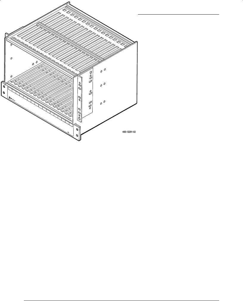
Figure 1-1. COMSPHERE 3000 Series Carrier
An optional fan module for the ac carriers is available to provide forced air cooling to dissipate heat generated within the carrier. It is recommended that fully configured carriers and cabinets be installed with fan modules to extend the life of the equipment. Guidelines for fan module provisions are listed in Table 3-1 of the Fan Module Installation section in Chapter 3.
An SDCP is required for initial installation and for testing of 3600 Series DSUs, 3151 T1 CSUs, and 3161 T1 DSU/CSUs and their options. Models 3811 and 3911 dial/lease modems can be installed using the SDCP or AT commands from the attached DTE. The SDCP, in conjunction with the SDU, allows up to eight COMSPHERE 3000 Series Carriers to be managed from one control panel. Models 3551, 3611, and 3616 DSUs and Models 3811 and 3911 dial/lease modems are managed by either the COMSPHERE 6700 or 6800 Series Network Management System (NMS).
Within the carrier, the first slot (Slot 0) is reserved for the SDU. The SDU provides the required interface that daisy chains carriers together for NMS and/or SDCP control. In a cabinet configuration, connectivity between the DSUs in the individual carriers allows control of compatible units in the cabinet through a single NMS interface, a single SDCP, or both.
On the rear of the carrier is a pair of 50-pin connectors (P21 and P22) that provide the following network interfaces:
•Digital line interface for DSUs.
•Analog leased-line interface for dial/lease modems.
1-2 |
December 1994 |
3000-A2-GA31-80 |

Introduction
Network Interface Modules (NIMs) can be installed at the rear of the carrier (when not occupied by an Auxiliary Backplane) to provide the PSTN (dial) or switched
56 kbps digital service interface for both DSUs and dial/lease modems. There are nine different NIMs. For a list of the feature/part numbers of these NIMs, see Appendix B of this manual.
Alternatively, you can install up to two Auxiliary Backplanes at the rear of the carrier to allow Model 3151 T1 CSUs and Model 3161 T1 DSU/CSUs to provide an interface between a T1 digital network and Customer Premise Equipment (CPE).
A modular DSU or dial/lease modem is a circuit card that contains ªgold fingerº contacts on the rear edge of the card and is supplied with a rear connector plate. A rear connector plate has two DTE connectors, a 25-pin EIA-232 connector and a 25-pin CCITT V.35 connector. It allows removal of a modular circuit card without disconnecting the DTE cables at the rear of the carrier. Also, there are connector modules which have six ports and are supplied with the modular DSU-TDM or
DSU-MCMP circuit cards. These connector plates and modules function as interfaces between the modular circuit cards and the DTEs.
This manual describes the procedure for installing a COMSPHERE 3000 Series Carrier into a COMSPHERE 72-inch cabinet. A COMSPHERE 72-inch cabinet with available equipment-mounting dimensions of 63 inches high by 19 inches wide has the capacity to hold up to six carriers, allowing for a high-density installation combination of up to 96 DSUs and/or dial/lease modems. COMSPHERE 3000 Series Carriers can also be mounted in other types of EIA standard 19or 23-inch wide cabinets. (The heights of the other types of cabinets may vary.)
Technical Specifications
Table 1-1 lists the Technical specifications for the COMSPHERE 3000 Series Carrier.
Table 1-1 (1 of 6)
Technical Specifications for the COMSPHERE 3000 Series Carrier
Technical Specifications |
Criteria |
|
|
ENVIRONMENT |
|
Operating Temperature |
32_F (0_C) to 122_F (50_C) |
Relative Humidity |
5% to 95% (noncondensing) |
Storage Temperature |
±4_F (±20_C) to 158_F (70_C) |
Shock and Vibration |
Withstands normal shipping and handling |
|
|
POWER REQUIREMENTS |
|
Carrier with ac power supply |
|
(maximum capacity) |
|
100 Vac (approved for use with |
85 100 Vac, 47-63 Hz (3.0 amp, 175 watts at 100 Vac) |
Models 3811 and 3911) |
90 132 Vac, 60 Hz ±3 (3.0 amp, 216 watts at 115 Vac) |
115 Vac (approved for use with |
|
Models 3151, 3161, 3511, 3551, 3611, |
|
3616, 3811, and 3911) |
|
230 Vac (approved for use with |
220Ð240 Vac nominal, 47 to 63 Hz (1.5 amp, 175 watts |
Models 3811 and 3911) |
at 230 Vac) |
Fan Module |
|
100 Vac |
Supplied by carrier, 45 watts at 100 Vac |
115 Vac |
Supplied by carrier, 45 watts at 115 Vac |
230 Vac |
Supplied by carrier, 57 watts at 230 Vac |
Shared Diagnostic Control Panel (SDCP) |
|
100 Vac |
Supplied by carrier, 1 watt at 100 Vac |
115 Vac |
Supplied by carrier, 1 watt at 115 Vac |
230 Vac |
Supplied by carrier, 1 watt at 230 Vac |
|
|
3000-A2-GA31-80 |
December 1994 |
1-3 |

COMSPHERE 3000 Series Carrier
Table 1-1 (2 of 6)
Technical Specifications for the COMSPHERE 3000 Series Carrier
Technical Specifications |
|
Criteria |
|
|
|
POWER REQUIREMENTS (Cont'd) |
|
Vac (CT), 60 Hz ±3 (0.01 amp, 1.5 watts at 115 Vac) |
Shared Diagnostic Unit (SDU) |
24 |
|
Model 3151 |
24 |
Vac (CT), 60 Hz ±3 (3.7 watts at 115 Vac) |
Model 3161 |
24 |
Vac (CT), 60 Hz ±3 (9.3 watts at 115 Vac) |
Model 3511 |
24 |
Vac (CT), 60 Hz ±3 (0.07 amp, 6 watts at 115 Vac) |
Models 3551 and 3611 |
24 |
Vac (CT), 60 Hz ±3 (0.03 amp, 4.5 watts at 115 Vac) |
DBM-V, DBM-S, or DBM-D |
24 |
Vac (CT), 60 Hz ±3 (0.05 amp, 8.0 watts at 115 Vac) |
Models 3551, 3611, and 3616 with DBM |
24 |
Vac (CT), 60 Hz ±3 (0.05 amp, 8.0 watts at 115 Vac) |
Model 3611 with TDM |
24 |
Vac (CT), 60 Hz ±3 (0.07 amp, 8.6 watts at 115 Vac) |
Model 3611 with DBM and TDM |
24 |
Vac (CT), 60 Hz ±3 (0.09 amp, 12.15 watts at 115 Vac) |
Model 3611 with MCMP |
24 |
Vac (CT), 60 Hz ±3 (0.08 amp, 9.1 watts at 115 Vac) |
Model 3611 with DBM and MCMP |
24 |
Vac (CT), 60 Hz ±3 (0.10 amp, 12.65 watts at 115 Vac) |
Model 3811 modem |
24 |
Vac (CT), 47Ð63 Hz (0.05 amp, 3.4 watts at 100 Vac) |
|
24 |
Vac (CT), 60 Hz ±3 (0.04 amp, 3.4 watts at 115 Vac) |
|
24 |
Vac (CT), 47Ð63 Hz (0.02 amp, 3.4 watts at 230 Vac) |
Model 3911 modem |
24 |
Vac (CT), 47Ð63 Hz (0.07 amp, 4.0 watts at 100 Vac) |
|
24 |
Vac (CT), 60 Hz ±3 (0.06 amp, 4.0 watts at 115 Vac) |
|
24 |
Vac (CT), 47Ð63 Hz (0.03 amp, 4.0 watts at 230 Vac) |
Carrier with sixteen 3551, 3611, and 3616 |
90Ð132 Vac, 60 Hz ±3 (1.65 amp, 165 watts at 115 Vac) |
|
DSUs with DBMs plus SDU and fan module |
|
|
Carrier with sixteen 3151 CSUs plus SDU, |
90Ð132 Vac, 60 Hz ±3 (1.25 amp, 111 watts at 115 Vac) |
|
SDCP, and fan module |
|
|
Carrier with sixteen 3161 DSU/CSUs plus |
90Ð132 Vac, 60 Hz ±3 (2.4 amp, 215 watts at 115 Vac) |
|
SDU, SDCP, and fan module |
|
|
|
|
|
FAN MODULE POWER DISSIPATION |
|
|
100 Vac |
154 Btu/hr |
|
115 Vac |
154 Btu/hr |
|
230 Vac |
195 Btu/hr |
|
|
|
|
1-4 |
December 1994 |
3000-A2-GA31-80 |

Introduction
|
Table 1-1 |
|
|
(3 of 6) |
|
Technical Specifications for the COMSPHERE 3000 Series Carrier |
||
|
|
|
Technical Specifications |
|
Criteria |
|
|
|
HEAT DISSIPATION (MAX.) |
|
|
Shared Diagnostic Unit (SDU) |
5.2 Btu/hr |
|
Model 3151 T1 CSU |
12.6 |
Btu/hr (3.7 watts) |
Model 3161 T1 DSU/CSU |
31.7 |
Btu/hr (99.3 watts) |
Model 3511 DSU |
20.5 |
Btu/hr |
Models 3551 and 3611 DSUs |
22.2 |
Btu/hr |
DBM-V, DBM-S, or DBM-D |
29.0 |
Btu/hr |
Models 3551, 3611, and 3616 with DBM |
29.0 |
Btu/hr |
Model 3611 with TDM |
33.4 |
Btu/hr |
Model 3611 with MCMP |
33.4 |
Btu/hr |
Model 3811 modem |
11.7 Btu/hr |
|
Model 3911 modem |
13.7 |
Btu/hr |
|
|
|
PHYSICAL DIMENSIONS |
|
|
Carrier |
|
|
Height |
10.5 inches (26.7 cm) |
|
Width |
19.0 inches (48.3 cm) |
|
Depth |
14.0 inches (35.6 cm) |
|
Power Transformer Unit |
|
|
Height |
2.5 inches (6.4 cm) |
|
Width |
16.9 inches (42.9 cm) |
|
Depth |
6.5 inches (16.5 cm) |
|
Fan Module |
|
|
Height |
1.8 inches (4.4 cm) |
|
Width |
19.0 inches (48.3 cm) |
|
Depth |
5.0 inches (12.7 cm) |
|
Shared Diagnostic Control Panel (SDCP) or |
|
|
Speaker Panel |
|
|
Height |
2.6 inches (6.5 cm) |
|
Width (length) |
19.0 inches (48.3 cm) |
|
Depth |
0.8 inches (1.1 cm) |
|
Shared Diagnostic Unit (SDU) |
|
|
Height |
7.1 inches (18.1 cm) |
|
Width |
1.0 inches (2.5 cm) |
|
Depth |
12.9 inches (32.8 cm) |
|
Models 3511, 3551, 3611, 3616, 3811, and |
|
|
3911 |
|
|
Height |
7.1 inches (18.1 cm) |
|
Width (thickness) |
1.0 inches (2.5 cm) |
|
Depth |
13.4 inches (34.0 cm) |
|
|
|
|
3000-A2-GA31-80 |
December 1994 |
1-5 |

COMSPHERE 3000 Series Carrier
|
Table 1-1 |
|
(4 of 6) |
Technical Specifications for the COMSPHERE 3000 Series Carrier |
|
|
|
Technical Specifications |
Criteria |
|
|
PHYSICAL DIMENSIONS (Cont'd) |
|
Model 3611 with TDM or MCMP |
|
Height |
7.1 inches (18.1 cm) |
Width (widest-point faceplates) |
2.0 inches (5.0 cm) |
Depth |
13.4 inches (34.0 cm) |
Models 3151 and 3161 |
|
Height |
7.1 inches (18.0 cm) |
Width |
1.0 inches (2.5 cm) |
Depth |
14.2 inches (36.1 cm) |
Rear Connector Plate (2-port) |
|
Height |
5.2 inches (13.2 cm) |
Width |
0.9 inches (2.3 cm) |
Depth (25-pin V.35 Interface) |
1.0 inches (2.5 cm) |
Connector Module (6-port) |
|
Height |
6.9 inches (17.5 cm) |
Width |
1.8 inches (4.6 cm) |
Depth |
3.3 inches (8.4 cm) |
Auxiliary Backplane |
|
Height |
9.0 inches (22.9 cm) |
Width |
8.0 inches (20.3 cm) |
Depth |
1.3 inches (3.3 cm) |
|
|
WEIGHT |
|
Carrier (empty) |
17.0 pounds (7.7 kg) |
Power Transformer Unit |
|
100 Vac |
14.6 pounds (6.6 kg) |
115 Vac |
19.0 pounds (8.6 kg) |
230 Vac |
14.1 pounds (6.4 kg) |
Fan Module |
|
100 Vac |
6.7 pounds (3.0 kg) |
115 Vac |
8.0 pounds (3.6 kg) |
230 Vac |
7.5 pounds (3.4 kg) |
Shared Diagnostic Control Panel (SDCP) |
1.6 pounds (0.7 kg) |
Rear Connector Plate (2-port) |
|
25-pin EIA-232/25-pin V.35 |
0.1 pounds (0.06 kg) |
Connector Module (6-port) |
1.0 pound (0.5 kg) |
Speaker Panel |
1.3 pounds (0.6 kg) |
Shared Diagnostic Unit (SDU) |
1.0 pounds (0.5 kg) |
Network Interface Module (NIM) |
0.2 pounds (0.1 kg) |
Model 3151 |
1.3 pounds (0.6 kg) |
Model 3161 |
1.8 pounds (0.82 kg) |
Auxiliary Backplane |
2.4 pounds (1.1 kg) |
|
|
1-6 |
December 1994 |
3000-A2-GA31-80 |

Introduction
Table 1-1 (5 of 6)
Technical Specifications for the COMSPHERE 3000 Series Carrier
Technical Specifications |
Criteria |
|
|
NETWORK INTERFACE |
Full Compliance with AT&T Technical Reference |
|
62310±1987, ``Digital Data System Channel Interface |
|
Specification,º November 1987; and Bell Canada ``Digital |
|
Circuit Terminating Equipment (DCTE) Specifications,º |
|
July 1989, Issue 1 |
Digital/Lease Network Interface |
(2) 50-pin connector |
|
Digital: USOC RJ48T |
|
Lease: 50-pin to 8-pin cable; JM8 |
Network Interface Module: |
(1 or 2) 50-pin connector |
Dial |
Permissive: USOC RJ21X |
|
Programmable: USOC RJ27X |
4-wire Switched 56 (U.S. only) |
(1 or 2) 50-pin connector; USOC SJA57 |
2-wire Switched 56 |
(1 or 2) 50-pin connector |
Model 3151 and 3161 Physical Interface |
|
USA |
(1 or 2) 50-pin connector; RJ48H (T1) |
Canada |
CA81A (T1 with adapter cable) |
|
|
DTE INTERFACE |
|
Model 3151 |
|
Physical Interface |
DB15S |
Framing Format |
D4, ESF |
Coding Format |
AMI, B8ZS |
DTE Line Equalization |
5 selectable ranges from 0 to 655 feet (0 to 196.5 meters) |
Send AIS |
Selectable |
Model 3161 (DSX-1) |
|
Physical Interface |
DB15S |
Framing Format |
D4, ESF |
Coding Format |
AMI, B8ZS |
DTE Line Equalization |
5 selectable ranges from 0 to 655 feet (0 to 196.5 meters) |
Send AIS |
Selectable |
|
|
MODEL 3161 PORT INTERFACE |
|
Standards |
EIA 530A, V.35, RS-449, V.11 |
Rates |
Nx64 ± 64-1.536 Mb |
|
Nx56 ± 56-1.344 Mb |
|
|
3000-A2-GA31-80 |
December 1994 |
1-7 |
COMSPHERE 3000 Series Carrier
Table 1-1 (6 of 6)
Technical Specifications for the COMSPHERE 3000 Series Carrier
Technical Specifications |
Criteria |
|
|
MODEL 3161 CLOCKING SOURCES |
T1 network interface, DSX-1 T1 interface, Port 1, internal |
|
clock, external clock |
|
|
APPROVALS |
|
Underwriters Laboratories, Inc. (UL) |
UL Standard for Safety, UL 1950 |
Recognized Component |
|
Canadian Standards Association |
CSA Standard C22.2 No. 950-M89 |
Certified Component |
|
|
|
Equipment Warranty
and Support
AT&T Paradyne's Customer Assistance Center is available 24 hours a day to help you place an installation request, report a hardware or software problem, or place a trouble report. The center provides technical support and remotely diagnoses equipment problems Monday through Friday, between the hours of 8 a.m. and 8 p.m. EST, excluding holidays. You can also call the center if you participate in the on-site support program (refer to the Enhanced Support Services section) or if you would like to request support on a time and materials basis.
Call the following toll-free number to reach the Customer Assistance Center:
1-800-237-0016
NOTE
Effective January 1, 1995, the Customer Assistance Center is available to provide technical support 24 hours a day,
365 days a year.
Equipment Service
To obtain service under your warranty, call the Customer Assistance Center at the number listed above. Please have the following information available before you call:
Company Name and Address
Contact Name and Telephone Number
Shipping Address, if different from the company address
Billing Address, if different than the shipping address
Model Number and Serial Number of the unit A brief description of the problem
The Customer Assistance Center will verify that the equipment is in need of repair. You are provided a Return Materials Authorization (RMA) number to help expedite the repair request. Once you receive an RMA number, pack the unit securely and ship the package insured and postage prepaid to:
AT&T Paradyne Corporation
Customer Support
Attn: Repair Center
8550 Ulmerton Road, Building B
Largo, Florida 34641
Make sure the RMA number is in a visible location on the outside of the package.
1-8 |
December 1994 |
3000-A2-GA31-80 |

Introduction
Out of Warranty
If your equipment is out of warranty and you do not have a maintenance support agreement, factory repair support is available.
To send equipment to AT&T Paradyne's Repair Center, call the following toll-free number Monday through Friday, between the hours of 8 a.m. and 5 p.m. EST, excluding holidays:
1-800-772-7691
Please have your purchase order number and the information listed in the Equipment Service section ready when you call for your RMA number. Package and ship the equipment to the Repair Center as described, making sure the RMA number is clearly visible on the outside of the package.
Enhanced Support Services
In addition to the customer support described, AT&T Paradyne offers a wide variety of enhanced customer support programs that are designed to meet our customers needs. Our high quality support programs range from equipment installation to premium on-site support, as well as network management.
For more information about our enhanced support services, contact your AT&T Paradyne representative, or call the following toll-free number, 8 a.m. to 5 p.m. EST, excluding holidays:
1-800-482-3333
3000-A2-GA31-80 |
December 1994 |
1-9 |

COMSPHERE 3000 Series Carrier
This page intentionally left blank.
1-10 |
December 1994 |
3000-A2-GA31-80 |

Installation Planning 2
Overview . . . . . . . . . . . . . . . . . . . . . . . . . . . . . . . . . . . . . . . . . . . . . . . . . . . . . . . . . . . . . . . . . . . . . . 2-1
Customer Responsibilities. . . . . . . . . . . . . . . . . . . . . . . . . . . . . . . . . . . . . . . . . . . . . . . . . . . . . . . . . . 2-2
Installation Considerations . . . . . . . . . . . . . . . . . . . . . . . . . . . . . . . . . . . . . . . . . . . . . . . . . . . . . . . . . 2-2
Overview
Before installing your COMSPHERE 3000 Series Carrier into a COMSPHERE cabinet (or equivalent), verify that you have everything you need to complete the installation, and that you have ordered the appropriate components.
The following steps are required for planning the installation of the carrier:
•Preparing the site.
•Determining the necessary components for your carrier.
•Securing ac power with proper grounding for your new equipment.
The following steps are required for the installation of the carrier and related components:
•Setting up the carrier cabinet.
•Installing the carrier(s) and removing the cover plate.
•Installing the Shared Diagnostic Control Panel ribbon cable if a Shared Diagnostic Control Panel (SDCP) is to be installed.
•Installing the power transformer unit.
•Installing the fan module, if applicable.
•Mounting the SDCP, if applicable, or replacing the cover plate.
•Mounting the speaker panel for Models 3811 and 3911 dial/lease modems, if applicable, between multiple carriers.
•Inter-connecting the Shared Diagnostic Unit (SDU) between carriers, if applicable.
•Connecting the SDU to an NMS, if applicable, between multiple carriers.
•Connecting the network cables.
•Installing a frame ground/signal ground strap.
•Connecting the carrier to an alarm output, if required.
•Supplying ac power to the carrier.
•Installing the rear connector plates and/or connector modules for modular devices, if applicable.
•Installing the Network Interface Modules (NIMs).
•Installing the 3151/3161 Auxiliary Backplanes, if needed.
•Installing the devices and/or filler panels. (Filler panels are required for unfilled slots in the carrier.)
3000-A2-GA31-80 |
December 1994 |
2-1 |

COMSPHERE 3000 Series Carrier
Customer Responsibilities
Preparing the installation site, including securing ac power with proper grounding, and verifying that you have the appropriate components for your site requirements are your responsibility. You can call your AT&T Paradyne representative, however, if you need assistance or have any questions.
When you order your COMSPHERE 3000 Series Carrier, certain components are supplied with your carrier; other components must be ordered separately.
Supplied with the carrier:
•3000 Series Carrier assembly
•Fuses
•Cable ties
•Signal ground/frame ground strap
You are responsible for ordering/supplying the following equipment:
•COMSPHERE 72-inch cabinet, or other non-AT&T Paradyne EIA standard 19or 23-inch wide cabinet.
•Power transformer unit.
•Fan module(s), if needed.
•SDCP.
•Speaker panel (for use with the Models 3811 and 3911 modems), if needed.
•One digital or leased network interface cable for each of the eight DSUs or modems.
•TDM (and MCMP) and/or digital bridge interface cables, if needed.
•One or two Network Interface Modules (NIMs), if needed.
•One or two dial network interface cables, if needed.
•Connecting cables and cords. (For a complete list of the available cables and cords, see Appendix B of this manual.)
•Rear connector plates for optional pre-mounting. (Modular devices are packaged with rear connector plates, but you can also order rear connector plates separately.)
•Shared Diagnostic Unit (SDU), if needed.
•3151/3161 Auxiliary Backplanes, if needed.
•T1 CSUs, T1 DSU/CSUs, DSUs, DBM-Vs, DBM-Ss, DBM-Ds, and/or dial/lease modems, and options needed (DBMs, TDMs, MCMPs).
•Filler panels for empty slots.
•Applicable manuals
An equipment list is included at the end of this manual to assist you in ordering any additional components you may require.
Installation Considerations
Your installation site should be well-ventilated, clean, and free of environmental extremes. There should be 2 to 3 feet of clearance at the front and rear of the cabinet in which the carrier is to be installed to allow access for installation of the power transformer unit, (optional) fan module, and (optional) SDCP, as well as the network interface connectors, rear connector plates, and DTE cables.
HANDLING PRECAUTIONS
FOR
STATIC SENSITIVE DEVICES
AT&T Paradyne products are designed to protect sensitive components from damage due to electrostatic discharge (ESD) during normal operation. When performing installation procedures, however, take proper static control precautions to prevent damage to equipment. If you are not sure of the proper static control precautions, contact the nearest AT&T Paradyne Customer Support office.
2-2 |
December 1994 |
3000-A2-GA31-80 |

Installation Planning
One COMSPHERE 72-inch cabinet can accommodate up to six COMSPHERE 3000 Series Carriers. A cabinet does not need to be fully populated with carriers, however. There are several general rules to follow during installation of the carrier.
1.If installing multiple carriers, install the lower one first, and if installing a full cabinet of carriers, install the carriers from the bottom of the cabinet and work up. This provides the following:
a.Proper alignment for subsequent carriers.
b.Easier carrier installation since they can be placed in the mounting and lowered onto the mounting screws.
c.Easier connection of the DTE interface.
d.Proper cabinet balance. Bottom-up installation keeps the cabinet from becoming top heavy.
2.You must mount carriers when they are empty.
If a carrier is installed in an EIA standard 23-inch (wide) cabinet, however, the mounting brackets on the carrier must be reversed before the carrier is mounted. Carriers can be installed in either EIA standard 19or 23-inch (wide) cabinets.
Models 3551, 3611, and 3616 DSUs and Models 3811 and 3911 dial/ lease modems within the COMSPHERE 3000 Series Carrier(s) can be managed from an SDCP, a Network Management System (NMS), or both. Remember that the Models 3551, 3611, and 3616 DSUs and Models 3811 and 3911 dial/lease modems are managed by the 6700 or 6800 Series NMS. A COMSPHERE 3000 Series Carrier cannot be connected to both a 6700 Series NMS and a 6800 Series NMS at the same time.
The location of the SDCP within the cabinet should be determined ahead of time. It should be installed at a convenient level, usually at eye-level. In a fully configured cabinet, this would be the fourth or fifth carrier from the bottom. Note that the Model 3511 DSUs are not capable of being managed by an SDCP.
The alarm output connection is closed, activating the customer-supplied alarm, when any DSU or Model 3811 or 3911 dial/lease modem in the carrier has an alarm condition that lights the red Alrm LED of the DSU or modem. For information on how to connect the alarm output, see the Alarm Output Connection section in Chapter 3.
Up to eight carriers can be controlled by an SDCP, but there must be a Shared Diagnostic Unit (SDU) installed in each carrier. (Slot 0 in each carrier is reserved for the SDU.) The SDU provides the interface that connects the SDCP to other carriers. Cabling is required that daisy chains these interfaces together.
If the units in the carriers are to be managed from an NMS, an SDU is required in all carriers. Up to eight carriers can be daisy chained together.
Cooling requirements should be given consideration. Depending upon the number of units in the carrier and how they are equipped, a fan module may be recommended. Table 3-1 in Chapter 3 will help you determine whether or not you need additional cooling for your carrier.
Two 50-pin connectors (P21 and P22) at the rear of the carrier, each serving eight slots, provide the digital interface for DSUs and the analog leased-line interface for dial/lease modems. DSUs and dial/lease modems can be placed in the same carrier, but they should be grouped together, (e.g., eight DSUs with a digital interface and eight dial/lease modems with an analog leased-line interface).
3000-A2-GA31-80 |
December 1994 |
2-3 |

COMSPHERE 3000 Series Carrier
If modular devices are installed in the same carrier as non-modular devices, the modular devices must be installed to the left of all other devices, as viewed from the front of the carrier.
If your carriers are equipped with DSUs with DBMs, dial/lease modems, or modems having dial backup capability, the half of the carrier containing those devices must have a Network Interface Module (NIM) installed to provide a dial network or switched 56 kbps digital service interface. Since one module serves eight slots, it is best to group units with dial capability.
NIMs can be installed at the rear of the carrier. There is a total of nine different NIMs available.
The carrier's backplane contains connectors which automatically engage mating connectors on DSUs (and TDM or MCMP circuit cards, if installed) or dial/lease modems when they are installed. To prevent accidental contact with these connectors, use filler panels for unfilled slots. Verify that you have ordered a sufficient quantity.
To use 3151 CSUs or 3161 DSU/CSUs in the carrier, you must remove any rear connector plates or modules and add the 3151/3161 Auxiliary Backplane. Using a single Auxiliary Backplane, you can install any combination of up to eight 3151 CSUs and 3161 DSU/CSUs on one side of the 3000 Series Carrier, and up to eight 3600, 3800, and 3900 Series devices on the other side of the carrier. Alternatively, using two Auxiliary Backplanes, you can install up to sixteen 3151 CSUs or 3161 DSU/CSUs in a single 3000 Series Carrier.
For each non-modular TDM or MCMP circuit card installed in the carrier, determine whether the circuit card is to be used as a Time Division Multiplexer (TDM) or as a digital bridge. A TDM interface cable is supplied with each non-modular TDM or MCMP circuit card. However, a digital bridge interface cable must be ordered separately.
For modular TDM or MCMP circuit cards, use standard cables for Ports 1 through 6. However, a 6-port V.35 interconnect cable is required for the 26-pin high-density D-type connector on the connector module. This cable must be ordered separately.
It is recommended that you do not perform any procedure that removes power to the carrier (for example, replacing the power transformer unit or disconnecting power to the power transformer to install an SDCP in a fully configured carrier) during peak operating hours since disconnecting power disables all units in the carrier.
2-4 |
December 1994 |
3000-A2-GA31-80 |

|
Installation |
3 |
Overview . . . . . . . . . . . . . . . . . . . . . . . . . . . . . . . . . . . . . . . . . . . . . . |
. . . . . . . . . . . . . . . . . . . . . . . . . . . 3-2 |
|
Cabinet Unpacking and Setup . . . . . . . . . . . . . . . . . . . . . . . . . . . . . . . . |
. . . . . . . . . . . . . . . . . . . . . . . . . . 3-4 |
|
Presetup Inspection . . . . . . . . . . . . . . . . . . . . . . . . . . . . . . . . . . . . . |
. . . . . . . . . . . . . . . . . . . . . . . . . . 3-4 |
|
Unpacking the Cabinet . . . . . . . . . . . . . . . . . . . . . . . . . . . . . . . . . . |
. . . . . . . . . . . . . . . . . . . . . . . . . . 3-4 |
|
Cabinet Setup . . . . . . . . . . . . . . . . . . . . . . . . . . . . . . . . . . . . . . . . . |
. . . . . . . . . . . . . . . . . . . . . . . . . . 3-5 |
|
Leveling the Cabinet . . . . . . . . . . . . . . . . . . . . . . . . . . . . . . . . . |
. . . . . . . . . . . . . . . . . . . . . . . . . . 3-5 |
|
Reversing the Cabinet Doors . . . . . . . . . . . . . . . . . . . . . . . . . . . |
. . . . . . . . . . . . . . . . . . . . . . . . . . 3-5 |
|
Carrier Installation . . . . . . . . . . . . . . . . . . . . . . . . . . . . . . . . . . . . . . . . |
. . . . . . . . . . . . . . . . . . . . . . . . . . 3-5 |
|
Preinspection Installation . . . . . . . . . . . . . . . . . . . . . . . . . . . . . . . . |
. . . . . . . . . . . . . . . . . . . . . . . . . . 3-5 |
|
Installation . . . . . . . . . . . . . . . . . . . . . . . . . . . . . . . . . . . . . . . . . . . . |
. . . . . . . . . . . . . . . . . . . . . . . . . . 3-6 |
|
Power Transformer Unit Installation . . . . . . . . . . . . . . . . . . . . . . . . . . |
. . . . . . . . . . . . . . . . . . . . . . . . . . 3-10 |
|
Preinstallation Inspection . . . . . . . . . . . . . . . . . . . . . . . . . . . . . . . . |
. . . . . . . . . . . . . . . . . . . . . . . . . . 3-10 |
|
Installation . . . . . . . . . . . . . . . . . . . . . . . . . . . . . . . . . . . . . . . . . . . |
. . . . . . . . . . . . . . . . . . . . . . . . . . 3-10 |
|
SDCP Ribbon Cable Installation . . . . . . . . . . . . . . . . . . . . . . . . |
. . . . . . . . . . . . . . . . . . . . . . . . . . 3-10 |
|
Power Transformer Unit Installation . . . . . . . . . . . . . . . . . . . . . |
. . . . . . . . . . . . . . . . . . . . . . . . . . 3-11 |
|
SGRD/FGRD Connection . . . . . . . . . . . . . . . . . . . . . . . . . . . . . |
. . . . . . . . . . . . . . . . . . . . . . . . . . 3-12 |
|
Alarm Output Connection . . . . . . . . . . . . . . . . . . . . . . . . . . . . . |
. . . . . . . . . . . . . . . . . . . . . . . . . . 3-13 |
|
Fan Module Installation . . . . . . . . . . . . . . . . . . . . . . . . . . . . . . . . . . . . |
. . . . . . . . . . . . . . . . . . . . . . . . . . 3-15 |
|
Preinstallation Inspection . . . . . . . . . . . . . . . . . . . . . . . . . . . . . . . . |
. . . . . . . . . . . . . . . . . . . . . . . . . . 3-15 |
|
Installation . . . . . . . . . . . . . . . . . . . . . . . . . . . . . . . . . . . . . . . . . . . . |
. . . . . . . . . . . . . . . . . . . . . . . . . . 3-15 |
|
Shared Diagnostic Control Panel (SDCP) Installation . . . . . . . . . . . . . |
. . . . . . . . . . . . . . . . . . . . . . . . . . 3-17 |
|
Preinstallation Inspection . . . . . . . . . . . . . . . . . . . . . . . . . . . . . . . . |
. . . . . . . . . . . . . . . . . . . . . . . . . . 3-18 |
|
Installation . . . . . . . . . . . . . . . . . . . . . . . . . . . . . . . . . . . . . . . . . . . . |
. . . . . . . . . . . . . . . . . . . . . . . . . . 3-18 |
|
Speaker Panel Installation . . . . . . . . . . . . . . . . . . . . . . . . . . . . . . . . . . |
. . . . . . . . . . . . . . . . . . . . . . . . . . 3-19 |
|
Preinstallation Inspection . . . . . . . . . . . . . . . . . . . . . . . . . . . . . . . . |
. . . . . . . . . . . . . . . . . . . . . . . . . . 3-19 |
|
Installation . . . . . . . . . . . . . . . . . . . . . . . . . . . . . . . . . . . . . . . . . . . |
. . . . . . . . . . . . . . . . . . . . . . . . . . 3-19 |
|
Shared Diagnostic Unit (SDU) Installation . . . . . . . . . . . . . . . . . . . . . |
. . . . . . . . . . . . . . . . . . . . . . . . . . 3-22 |
|
Preinstallation Inspection . . . . . . . . . . . . . . . . . . . . . . . . . . . . . . . . |
. . . . . . . . . . . . . . . . . . . . . . . . . . 3-22 |
|
Installation . . . . . . . . . . . . . . . . . . . . . . . . . . . . . . . . . . . . . . . . . . . . |
. . . . . . . . . . . . . . . . . . . . . . . . . . 3-24 |
|
NMS Connection . . . . . . . . . . . . . . . . . . . . . . . . . . . . . . . . . . . . . . . |
. . . . . . . . . . . . . . . . . . . . . . . . . . 3-27 |
|
Auxiliary Backplane Installation . . . . . . . . . . . . . . . . . . . . . . . . . . . . . |
. . . . . . . . . . . . . . . . . . . . . . . . . . 3-32 |
|
COM Port Connection ± External PC . . . . . . . . . . . . . . . . . . . . . . . |
. . . . . . . . . . . . . . . . . . . . . . . . . . 3-36 |
|
Network Interface Installation . . . . . . . . . . . . . . . . . . . . . . . . . . . . . . . |
. . . . . . . . . . . . . . . . . . . . . . . . . . 3-37 |
|
Digital or Analog Leased-Line Network Interfaces . . . . . . . . . . . . |
. . . . . . . . . . . . . . . . . . . . . . . . . . 3-42 |
|
Dial Network Interface . . . . . . . . . . . . . . . . . . . . . . . . . . . . . . . . . . |
. . . . . . . . . . . . . . . . . . . . . . . . . . 3-42 |
|
2-Wire Switched 56 kbps Network Interface . . . . . . . . . . . . . . . . . |
. . . . . . . . . . . . . . . . . . . . . . . . . . 3-43 |
|
4-Wire Switched 56 kbps Network Interface . . . . . . . . . . . . . . . . . |
. . . . . . . . . . . . . . . . . . . . . . . . . . 3-43 |
|
NIM Installation . . . . . . . . . . . . . . . . . . . . . . . . . . . . . . . . . . . . . . . |
. . . . . . . . . . . . . . . . . . . . . . . . . . 3-44 |
|
COMSPHERE 3811 Control Interface . . . . . . . . . . . . . . . . . . . . . . |
. . . . . . . . . . . . . . . . . . . . . . . . . . 3-45 |
|
Models 3151 and 3161 Network Interface . . . . . . . . . . . . . . . . . . . |
. . . . . . . . . . . . . . . . . . . . . . . . . . 3-45 |
|
Circuit Card Installation . . . . . . . . . . . . . . . . . . . . . . . . . . . . . . . . . . . . |
. . . . . . . . . . . . . . . . . . . . . . . . . . 3-47 |
|
Preinstallation Inspection . . . . . . . . . . . . . . . . . . . . . . . . . . . . . . . . |
. . . . . . . . . . . . . . . . . . . . . . . . . . 3-50 |
|
Modular Circuit Card Installation . . . . . . . . . . . . . . . . . . . . . . . . . . |
. . . . . . . . . . . . . . . . . . . . . . . . . . 3-50 |
|
Non-Modular Circuit Card Installation . . . . . . . . . . . . . . . . . . . . . |
. . . . . . . . . . . . . . . . . . . . . . . . . . 3-52 |
|
Models 3151 and 3161 Circuit Card . . . . . . . . . . . . . . . . . . . . . . . . |
. . . . . . . . . . . . . . . . . . . . . . . . . . 3-54 |
|
Filler Panels . . . . . . . . . . . . . . . . . . . . . . . . . . . . . . . . . . . . . . . . . . |
. . . . . . . . . . . . . . . . . . . . . . . . . . 3-54 |
|
3000-A2-GA31-80 |
December 1994 |
3-1 |

COMSPHERE 3000 Series Carrier
Overview
A COMSPHERE 72-inch cabinet is available for mounting the COMSPHERE 3000 Series Carriers. Up to six carriers can be mounted into a single cabinet. The COMSPHERE 3000 Series Carriers can also be mounted into other commercial EIA standard 19-inch and 23-inch cabinets.
The COMSPHERE 3000 Series Carrier, Figure 3-1, is designed to house T1 CSUs, T1 DSU/CSUs, DSUs, DBM-Vs, DBM-Ss, DBM-Ds, TDMs, MCMPs, and dial/lease modems. The carrier is a metal enclosure that contains slots for installation of 17 circuit cards. The slot labeled SDU (Slot 0) is reserved for the Shared Diagnostic Unit (SDU); Slots 1 through 16 are for T1 CSUs, T1 DSU/CSUs, DSUs, DBM-Vs, DBM-Ss, DBM-Ds, TDMs,
MCMPs, or dial/lease modems. Under each slot number (on the cover plate or SDCP) is a small area in which to write the circuit channel identification numbers.
The carrier's backplane contains connectors which automatically engage mating connectors on the devices as they are being installed. Filler panels (which must be ordered separately) are required for unfilled slots.
Two 50-pin connectors (P21 and P22) at the rear of the carrier (each serving eight carrier slots) provide an interface between the carrier and the digital line for DSUs and the carrier and the leased line for dial/lease modems. Above these are connectors for the dial network connections (P23 and P26). One or two network interface modules (each serving eight carrier slots) can be ordered, as needed, to establish dial network connections.
Figure 3-1. COMSPHERE 3000 Series Carrier Assembly
3-2 |
December 1994 |
3000-A2-GA31-80 |

Installation
There are nine NIMs available. The following NIMs are used with the 3600 Series DSUs/DBMs:
•Permissive NIM (for use with V.32 and 2-wire Switched 56 DBMs)
•Programmable NIM (for use with V.32 DBMs)
•4-wire Switched 56 NIM (for use with 4-wire Switched 56 DBMs)
WARNING
Do not connect a 2-wire switched 56 kbps plug into an RJ11C jack. This type of jack is intended for analog PSTN devices. Failure to do this may cause equipment damage and harm to the telephone network.
The following NIMs are used with the dial/lease modems, or a combination of DSUs with V.32 DBMs and dial/lease modems in the same carrier half:
•Permissive NIM (3911 only)
•Permissive NIM with the Make Busy feature
•Programmable NIM with the Make Busy feature (3811 only)
•Permissive NIM with the Service Line feature
•Programmable NIM with the Service Line feature (3811 only)
•Permissive NIM with both the Make Busy and Service Line features
•Programmable NIM with both the Make Busy and Service Line features (3811 only)
NOTE
You cannot use a NIM on the side of the carrier where an Auxiliary Backplane is installed.
Programmable mode corrects any loss in the transmit signal level between the modem and the central office by permitting the modem to transmit at the optimum signal level. This is accomplished by the local telephone company installing a resistor into the network interface and is usually identified by an RJ45S-type jack.
Permissive mode is a standard dial-line connection and is identified by the use of an RJ11Cor SJA48-type jack. (The carrier also supports RJ21Xand RJ27X-type mass termination interfaces for Permissive and Programmable modes, respectively.)
The DDD NIMs, programmable and permissive, may have Make Busy and Service Line as additional capabilities. The Make Busy feature is useful when modems are used in a ``huntº or ``rotaryº group. This feature ties the Tip and Ring signals together so that the modem appears busy. Make Busy is not used by DSUs with DBMs, but using a NIM with this feature will not affect the DBM's performance. The Service Line feature permits an extra dial line to be connected to a COMSPHERE 3000 Series Carrier. NIMs with this feature are identified by the two modular connectors mounted on the NIM.
WARNING
The Make Busy feature must only be used behind a PBX. Connecting a NIM with the Make Busy capability directly to the PSTN is a violation of FCC
Part 68 Rules and Canadian DOC CS-03 Regulations.
Non-modular DSUs equipped with TDM or MCMP circuit cards are supplied with time division multiplexer interface cables. If you plan to use the digital bridge function, you must order a digital bridge interface cable.
When modular DSUs or modems are to be installed in the carrier, rear connector plates or connector modules must be installed at the rear of the carrier. Modular DSUs and dial/lease modems are circuit cards that can be removed from the front of the carrier without disturbing the DTE cables attached to the rear connector plate at the rear of the carrier. Also, there are connector modules that are supplied with the modular DSU-TDM (or DSU-MCMP) circuit cards. These connector plates and modules function as interfaces between the modular circuit cards and the DTEs.
A power transformer unit provides low voltage
ac power to the carrier's internal power distribution bus. A carrier designed to operate from a ± 48 Vdc power unit is also available. This power unit is called the Central Office (CO) Power Unit and it consists of one dc power module. Note that an optional second power module is available. For more information on the CO Power Unit, see the COMSPHERE ± 48 Vdc Central Office Power Unit, Installation Guide.
3000-A2-GA31-80 |
December 1994 |
3-3 |
Loading...