


 Loading...
BitStorm® 4800 Express
Model 4821-A2
Installation Guide
Document No. 4821-A2-GN21-10
July 2004

Copyright © 2004 Paradyne Corporation.
All rights reserved.
Printed in U.S.A.
Notice
This publication is protected by federal copyright law. No part of this publication may be copied or distributed, transmitted, transcribed, stored in a retrieval system, or translated into any human or computer language in any form or by any means, electronic, mechanical, magnetic, manual or otherwise, or disclosed to third parties without the express written permission of Paradyne Corporation, 8545 126th Ave. N., Largo, FL 33773.
Paradyne Corporation makes no representation or warranties with respect to the contents hereof and specifically disclaims any implied warranties of merchantability or fitness for a particular purpose. Further, Paradyne Corporation reserves the right to revise this publication and to make changes from time to time in the contents hereof without obligation of Paradyne Corporation to notify any person of such revision or changes.
Changes and enhancements to the product and to the information herein will be documented and issued as a new release to this manual.
Warranty, Sales, Service, and Training Information
Contact your local sales representative, service representative, or distributor directly for any help needed. For additional information concerning warranty, sales, service, repair, installation, documentation, training, distributor locations, or Paradyne worldwide office locations, use one of the following methods:
Internet: Visit the Paradyne World Wide Web site at www.paradyne.com. (Be sure to register your warranty at www.paradyne.com/warranty.)
Telephone: Call our automated system to receive current information by fax or to speak with a company representative.
—Within the U.S.A., call 1-800-870-2221
—Outside the U.S.A., call 1-727-530-2340
Document Feedback
We welcome your comments and suggestions about this document. Please mail them to Technical Publications, Paradyne Corporation, 8545 126th Ave. N., Largo, FL 33773, or send e-mail to userdoc@paradyne.com. Include the number and title of this document in your correspondence. Please include your name and phone number if you are willing to provide additional clarification.
Trademarks
ACCULINK, BitStorm, COMSPHERE, FrameSaver, Hotwire, Jetstream, MVL, NextEDGE, OpenLane, Performance Wizard are registered trademarks of Paradyne Corporation. EtherLoop, GranDSLAM, GrandVIEW, iMarc, ReachDSL, StormTracker, and TruePut are trademarks of Paradyne Corporation. All other products and services mentioned herein are the trademarks, service marks, registered trademarks, or registered service marks of their respective owners.
A |
July 2004 |
4821-A2-GN21-10 |

Software and Firmware License Agreement
ONCE YOU HAVE READ THIS LICENSE AGREEMENT AND AGREE TO ITS TERMS, YOU MAY USE THE SOFTWARE AND/OR FIRMWARE INCORPORATED INTO THE PARADYNE PRODUCT. BY USING THE PARADYNE PRODUCT YOU SHOW YOUR ACCEPTANCE OF THE TERMS OF THIS LICENSE AGREEMENT.
IN THE EVENT THAT YOU DO NOT AGREE WITH ANY OF THE TERMS OF THIS LICENSE AGREEMENT, PROMPTLY RETURN THE UNUSED PRODUCT IN ITS ORIGINAL PACKAGING AND YOUR SALES RECEIPT OR INVOICE TO THE LOCATION WHERE YOU OBTAINED THE PARADYNE PRODUCT OR THE LOCATION FROM WHICH IT WAS SHIPPED TO YOU, AS APPLICABLE, AND YOU WILL RECEIVE A REFUND OR CREDIT FOR THE PARADYNE PRODUCT PURCHASED BY YOU.
The terms and conditions of this License Agreement (the “Agreement”) will apply to the software and/or firmware (individually or collectively the “Software”) incorporated into the Paradyne product (the “Product”) purchased by you and any derivatives obtained from the Software, including any copy of either. If you have executed a separate written agreement covering the Software supplied to you under this purchase, such separate written agreement shall govern.
Paradyne Corporation (“Paradyne”) grants to you, and you (“Licensee”) agree to accept a personal, non-transferable, non-exclusive, right (without the right to sublicense) to use the Software, solely as it is intended and solely as incorporated in the Product purchased from Paradyne or its authorized distributor or reseller under the following terms and conditions:
1.Ownership: The Software is the sole property of Paradyne and/or its licensors. The Licensee acquires no title, right or interest in the Software other than the license granted under this Agreement.
2.Licensee shall not use the Software in any country other than the country in which the Product was rightfully purchased except upon prior written notice to Paradyne and an agreement in writing to additional terms.
3.The Licensee shall not reverse engineer, decompile or disassemble the Software in whole or in part.
4.The Licensee shall not copy the Software except for a single archival copy.
5.Except for the Product warranty contained in the manual, the Software is provided “AS IS” and in its present state and condition and Paradyne makes no other warranty whatsoever with respect to the Product purchased by you. THIS AGREEMENT EXPRESSLY EXCLUDES ALL OTHER WARRANTIES, WHETHER EXPRESS OR IMPLIED, OR ORAL OR WRITTEN, INCLUDING WITHOUT LIMITATION:
a.Any warranty that the Software is error-free, will operate uninterrupted in your operating environment, or is compatible with any equipment or software configurations; and
b.ANY AND ALL IMPLIED WARRANTIES, INCLUDING WITHOUT LIMITATION IMPLIED WARRANTIES OF MERCHANTABILITY, FITNESS FOR A PARTICULAR PURPOSE AND NON-INFRINGEMENT.
Some states or other jurisdictions do not allow the exclusion of implied warranties on limitations on how long an implied warranty lasts, so the above limitations may not apply to you. This warranty gives you specific legal rights, and you may also have other rights which vary from one state or jurisdiction to another.
6.In no event will Paradyne be liable to Licensee for any consequential, incidental, punitive or special damages, including any lost profits or lost savings, loss of business information or business interruption or other pecuniary loss arising out of the use or inability to use the Software, whether based on contract, tort, warranty or other legal or equitable grounds, even if Paradyne has been advised of the possibility of such damages, or for any claim by any third party.
4821-A2-GN21-10 |
July 2004 |
B |

7.The rights granted under this Agreement may not be assigned, sublicensed or otherwise transferred by the Licensee to any third party without the prior written consent of Paradyne.
8.This Agreement and the license granted under this Agreement shall be terminated in the event of breach by the Licensee of any provisions of this Agreement.
9.Upon such termination, the Licensee shall refrain from any further use of the Software and destroy the original and all copies of the Software in the possession of Licensee together with all documentation and related materials.
This Agreement shall be governed by the laws of the State of Florida, without regard to its provisions concerning conflicts of laws.
! Important Safety Instructions
1.Read and follow all warning notices and instructions marked on the product or included in the manual.
2.This product is intended to be used with a 3-wire grounding type plug — a plug that has a grounding pin. This is a safety feature. Equipment grounding is vital to ensure safe operation. Do not defeat the purpose of the grounding type plug by modifying the plug or using an adapter. Prior to installation, use an outlet tester or a voltmeter to check the AC receptacle for the presence of earth ground. If the receptacle is not properly grounded, the installation must not continue until a qualified electrician has corrected the problem.
If a 3-wire grounding type power source is not available, consult a qualified electrician to determine another method of grounding the equipment.
3.Slots and openings in the cabinet are provided for ventilation. To ensure reliable operation of the product and to protect it from overheating, these slots and openings must not be blocked or covered.
4.Do not allow anything to rest on the power cord and do not locate the product where persons will walk on the power cord.
5.Do not attempt to service this product yourself, as it will void the warranty. Opening or removing covers may expose you to dangerous high voltage points or other risks. Refer all servicing to qualified service personnel.
6.General purpose cables are described for use with this product. Special cables, which may be required by the regulatory inspection authority for the installation site, are the responsibility of the customer. To reduce the risk of fire, use a UL Listed or CSA Certified, minimum No. 26 AWG (0.128 mm2) telecommunication cable, or comparable cables certified for use in the country of installation.
7.When installed in the final configuration, the product must comply with the applicable Safety Standards and regulatory requirements of the country in which it is installed. If necessary, consult with the appropriate regulatory agencies and inspection authorities to ensure compliance.
8.A rare phenomenon can create a voltage potential between the earth grounds of two or more buildings. If products installed in separate buildings are interconnected, the voltage potential may cause a hazardous condition. Consult a qualified electrical consultant to determine whether or not this phenomenon exists and, if necessary, implement corrective action prior to interconnecting the products.
9.In addition, if the equipment is to be used with telecommunications circuits, take the following precautions:
—Never install telephone wiring during a lightning storm.
—Never install telephone jacks in wet locations unless the jack is specifically designed for wet locations.
—Never touch uninsulated telephone wires or terminals unless the telephone line has been disconnected at the network interface.
—Use caution when installing or modifying telephone lines.
—Avoid using a telephone (other than a cordless type) during an electrical storm. There may be a remote risk of electric shock from lightning.
—Do not use the telephone to report a gas leak in the vicinity of the leak.
C |
July 2004 |
4821-A2-GN21-10 |

10.CLASS 1 LASER PRODUCT: This product has provisions for the customer to install a Class 1 laser transciever, which provides optical coupling to the telecommunication network. Once a Class 1 laser product is installed, the equipment is to be considered to be a Class 1 Laser Product (Appareil à Laser de Classe 1). The customer is responsible for selecting and installing the laser transciever and for insuring that the Class 1 AEL (Allowable Emission Limit) per EN/IEC 60825 is not exceeded after the laser transponders have been installed. Do not install laser products whose class rating is greater than 1. Refer to all important safety instructions that accompanied the transciever prior to installation. Only laser Class 1 devices, certified for use in the country of installation by the cognizant agency are to be utilized in this product.
11.The equipment is intended for installation in a max. 50° C ambient temperature, in an environment that is free of dust and dirt.
12.The power supply cord for countries other than North America is to be a minimum H05 V V-F type, min. 0.75 mm2, 2-conductor and earth ground terminated in an IEC 320 connector on one end, and a plug which is certified for use in the country of installation at the other end.
13.Do not physically stack more than eight (8) 26x1 units high. Physical stability has not been evaluated for stacking higher than eight units, and any configuration greater than eight may result in an unstable (tip-over) condition. Ensure that the four (4) rubber feet supplied with the product have been installed on the bottom of each unit prior to stacking any 26x1 units on top of one another.
EMI Notices
! UNITED STATES – EMI NOTICE:
This equipment has been tested and found to comply with the limits for a Class A digital device, pursuant to Part 15 of the FCC rules. These limits are designed to provide reasonable protection against harmful interference when the equipment is operated in a commercial environment. This equipment generates, uses, and can radiate radio frequency energy and, if not installed and used in accordance with the instruction manual, may cause harmful interference to radio communications. Operation of this equipment in a residential area is likely to cause harmful interference in which case the user will be required to correct the interference at his own expense.
The authority to operate this equipment is conditioned by the requirements that no modifications will be made to the equipment unless the changes or modifications are expressly approved by Paradyne Corporation.
If the equipment includes a ferrite choke or chokes, they must be installed per the installation instructions.
! CANADA – EMI NOTICE:
This Class A digital apparatus meets all requirements of the Canadian interference-causing equipment regulations.
Cet appareil numérique de la classe A respecte toutes les exigences du réglement sur le matérial brouilleur du Canada.
4821-A2-GN21-10 |
July 2004 |
D |
Notices to Users of the Canadian Telephone Network
NOTICE: This equipment meets the applicable Industry Canada Terminal Equipment Technical Specifications. This is confirmed by the registration number. The abbreviation IC before the registration number signifies that registration was performed based on a Declaration of Conformity indicating that Industry Canada technical specifications were met. It does not imply that Industry Canada approved the equipment.
NOTICE: The Ringer Equivalence Number (REN) for this terminal equipment is labeled on the equipment. The REN assigned to each terminal equipment provides an indication of the maximum number of terminals allowed to be connected to a telephone interface. The termination on an interface may consist of any combination of devices subject only to the requirement that the sum of the Ringer Equivalence Numbers of all the devices does not exceed five.
When the equipment is used in a customer premises environment, a Model 6051 POTS Splitter must be used to ensure CS-03 compliance. Refer to the POTS splitter installation instructions for details.
CE Marking
When the product is marked with the CE mark on the equipment label, a supporting Declaration of Conformity may be downloaded from the Paradyne World Wide Web site at www.paradyne.com. Select Library → Technical Manuals → CE Declarations of Conformity.
Japan
Class A ITE
This is a Class A product based on the standard of the Voluntary Control Council for interference by Information Technology Equipment (VCCI). If this equipment is used in a domestic environment, radio disturbance may arise. When such trouble occurs, the user may be required to take corrective actions.
E |
July 2004 |
4821-A2-GN21-10 |

Contents
About This Guide
Document Purpose and Intended Audience . . . . . . . . . . . . . . . . . . . . |
iii |
|
|
Document Summary . . . . . . . . . . . . . . . . . . . . . . . . . . . . . . . . . . . . . . |
iii |
|
Related Product Documents . . . . . . . . . . . . . . . . . . . . . . . . . . . . . . . . |
iv |
1 Installation
|
Overview . . . . . . . . . . . . . . . . . . . . . . . . . . . . . . . . . . . . . . . . . . . . . . . |
1-1 |
|
Preparation. . . . . . . . . . . . . . . . . . . . . . . . . . . . . . . . . . . . . . . . . . . . . . |
1-2 |
|
Cables Required . . . . . . . . . . . . . . . . . . . . . . . . . . . . . . . . . . . . . . . . . |
1-3 |
|
Unpacking the Hardware . . . . . . . . . . . . . . . . . . . . . . . . . . . . . . . . . . . |
1-4 |
|
Package Contents . . . . . . . . . . . . . . . . . . . . . . . . . . . . . . . . . . . . . . . . |
1-4 |
|
Mounting Configurations . . . . . . . . . . . . . . . . . . . . . . . . . . . . . . . . . . . |
1-6 |
|
Mounting Brackets . . . . . . . . . . . . . . . . . . . . . . . . . . . . . . . . . . . . . . . . |
1-6 |
Installing the Brackets for Rack Mounting . . . . . . . . . . . . . . . . . . . . . . |
1-6 |
|
Installing the BitStorm 4800 Express Into a Rack . . . . . . . . . . . . . . . . |
1-8 |
|
Installing the BitStorm 4800 Express on a Wall . . . . . . . . . . . . . . . . . . |
1-10 |
|
Installing the BitStorm 4800 Express on a Shelf or Desktop . . . . . . . . |
1-12 |
|
2 Cabling
|
Cabling Overview . . . . . . . . . . . . . . . . . . . . . . . . . . . . . . . . . . . . . . . . . |
2-1 |
|
DSL Ports. . . . . . . . . . . . . . . . . . . . . . . . . . . . . . . . . . . . . . . . . . . . . . . |
2-2 |
10/100BaseT Uplink (Port 2) . . . . . . . . . . . . . . . . . . . . . . . . . . . . . . . . |
2-3 |
|
|
Management Port. . . . . . . . . . . . . . . . . . . . . . . . . . . . . . . . . . . . . . . . . |
2-4 |
|
Console Port . . . . . . . . . . . . . . . . . . . . . . . . . . . . . . . . . . . . . . . . . . . . |
2-5 |
|
Connecting a Terminal or PC to the Console Port. . . . . . . . . . . . . |
2-5 |
|
Connecting a Modem to the Console Port. . . . . . . . . . . . . . . . . . . |
2-6 |
|
Ground . . . . . . . . . . . . . . . . . . . . . . . . . . . . . . . . . . . . . . . . . . . . . . . . . |
2-7 |
|
Connecting to Power . . . . . . . . . . . . . . . . . . . . . . . . . . . . . . . . . . . . . . |
2-8 |
3 LEDs
|
LED Locations . . . . . . . . . . . . . . . . . . . . . . . . . . . . . . . . . . . . . . . . . . . |
3-1 |
|
LED Meanings . . . . . . . . . . . . . . . . . . . . . . . . . . . . . . . . . . . . . . . . . . . |
3-2 |
4821-A2-GN21-10 |
July 2004 |
i |

Contents
4 Configuration
|
Overview . . . . . . . . . . . . . . . . . . . . . . . . . . . . . . . . . . . . . . . . . . . . . . . |
4-1 |
|
Using the CLI . . . . . . . . . . . . . . . . . . . . . . . . . . . . . . . . . . . . . . . . . . . |
4-2 |
|
Configure Management Default Gateway Address . . . . . . . . . . . . |
4-2 |
|
Configure Management Inband Address . . . . . . . . . . . . . . . . . . . . |
4-3 |
|
Configure Management Out-of-Band Address . . . . . . . . . . . . . . . |
4-3 |
BitStorm 4800 Express Startup Procedure . . . . . . . . . . . . . . . . . . . . . |
4-4 |
|
|
Login . . . . . . . . . . . . . . . . . . . . . . . . . . . . . . . . . . . . . . . . . . . . . . . |
4-4 |
|
Management Modes . . . . . . . . . . . . . . . . . . . . . . . . . . . . . . . . . . . |
4-4 |
Startup Procedure for Inband Management. . . . . . . . . . . . . . . . . . . . . |
4-5 |
|
Startup Procedure for Out-of-Band Management . . . . . . . . . . . . . . . . |
4-5 |
|
Using the Web Interface. . . . . . . . . . . . . . . . . . . . . . . . . . . . . . . . . . . . |
4-6 |
|
|
System / Users. . . . . . . . . . . . . . . . . . . . . . . . . . . . . . . . . . . . . . . . . . . |
4-7 |
Configuration / Management / SNMP . . . . . . . . . . . . . . . . . . . . . . . . . |
4-8 |
|
A Connectors and Pin Assignments
|
Overview . . . . . . . . . . . . . . . . . . . . . . . . . . . . . . . . . . . . . . . . . . . . . . . |
A-1 |
|
DSL Ports Connectors . . . . . . . . . . . . . . . . . . . . . . . . . . . . . . . . . . . . . |
A-2 |
Port 1 and Port 2 10/100BaseT Connectors . . . . . . . . . . . . . . . . . . . . |
A-3 |
|
|
Console Port Connector. . . . . . . . . . . . . . . . . . . . . . . . . . . . . . . . . . . . |
A-4 |
BEquipment List
CTechnical Specifications Index
ii |
July 2004 |
4821-A2-GN21-10 |

About This Guide
Document Purpose and Intended Audience
This document is written for technicians who install the BitStorm® 4800 Express
Model 4821-A2 IP DSLAM.
Document Summary
Section |
Description |
|
|
Chapter 1, Installation |
Describes the physical installation of the BitStorm 4800 |
|
Express into a rack. |
|
|
Chapter 2, Cabling |
Describes how to install all cables for the BitStorm 4800 |
|
Express. |
|
|
Chapter 3, LEDs |
Explains the meaning and usage of the front panel LEDs. |
|
|
Chapter 4, Configuration |
Describes the minimal configuration steps required to |
|
prepare the BitStorm 4800 Express for remote access, |
|
using the command line interface and web interface. |
|
|
Appendix A, Connectors |
Provides pinouts for connectors on the BitStorm 4800 |
and Pin Assignments |
Express. |
|
|
Appendix B, Equipment List |
Provides part numbers for the BitStorm 4800 Express and |
|
related products. |
|
|
Appendix C, Technical |
Lists the technical characteristics of the BitStorm 4800 |
Specifications |
Express. |
|
|
Index |
Lists key terms, acronyms, concepts, and sections in |
|
alphabetical order. |
|
|
A master glossary of terms and acronyms used in Paradyne documents is available on the World Wide Web at www.paradyne.com. Select Support → Technical Manuals → Technical Glossary.
4821-A2-GN21-10 |
July 2004 |
iii |

About This Guide
Related Product Documents
Documentation for the BitStorm 4800 Express IP DSLAM is available on the World Wide Web at www.paradyne.com. Select Support → Technical Manuals.
Document Number |
Document Title |
|
|
4821-A2-GB21 |
BitStorm 4800 Express Model 4821-A2 Command Line Interface |
|
Reference |
|
Describes the Command Line Interface (CLI) used to configure |
|
and monitor the BitStorm 4800 Express. |
|
|
4821-A2-GB22 |
BitStorm 4800 Express Model 4821-A2 SNMP Reference |
|
Contains the information necessary to use Simple Network |
|
Management Protocol (SNMP) to configure and monitor the |
|
BitStorm 4800 Express. |
|
|
6051-A2-GZ40 |
BitStorm 6051 POTS Splitter Installation Instructions |
|
Describes how to install the BitStorm 6051 POTS splitter. |
|
|
6210-A2-GB20 |
Hotwire 6210-A2, 6211-A2, and 6381-A2 User’s Guide |
|
Describes the installation and operation of the 6210 ADSL |
|
bridge, 6211 ADSL router, and 6381 ADSL/R router. |
|
|
7890-A2-GB22 |
GrandVIEW EMS User’s Guide |
|
Contains instructions for maintaining network services and |
|
resources using the GrandVIEW Element Management System |
|
(EMS). |
|
|
To order a paper copy of a Paradyne document, or to talk to a sales representative, please call 727-530-2000.
iv |
July 2004 |
4821-A2-GN21-10 |
Installation
1
Overview
The BitStorm® 4800 Express is a stackable IP DSLAM designed for installation in a Central Office (CO), multi-tenant unit (MTU), or multi-dwelling unit (MDU) environment.
CONSOLE |
PORT1 |
|
10/100BT |
1P0ORT2 /100BT
STATUSALARMTEST |
1 |
3 |
5 |
7 |
|
|||
2 |
4 |
6 |
8 |
9 |
11 |
13 |
15 |
|
|||
10 |
12 14 |
16 |
|
17 |
19 |
21 |
23 |
18 |
20 |
22 |
24 |
25 |
27 |
29 |
31 |
26 |
28 |
30 |
32 |
|
33 |
35 37 |
39 |
41 |
|
|
|
|
|
43 |
45 |
|
34 |
36 38 |
40 |
42 |
|
|
|
44 |
46 |
47 |
48 |
DSL PORTS 1-24
DSL
POTS 1-24
PORTS 25-48
04-17534
The BitStorm 4800 Express is interoperable with the Hotwire 6381 ADSL/R modem, as well as any standard ADSL CPE.
A Command Line Interface (CLI) and a web browser interface are provided. The unit also may be managed using a network manager such as the Paradyne GrandVIEW™ Element Management System (EMS).
BitStorm 4800 Express IP DSLAM models and features are listed in Table 1-1, BitStorm 4800 Express Models and Features.
Table 1-1. BitStorm 4800 Express Models and Features
Model Number |
Type |
Number of Ports |
|
|
|
4821-A2-427 |
ADSL |
24 |
|
|
|
4821-A2-447 |
ADSL |
48 |
|
|
|
4821-A2-GN21-10 |
July 2004 |
1-1 |

1. Installation
Preparation
Consider the following before installing the BitStorm 4800 Express IP DSLAM:
Installation Site
Your installation site should be well ventilated, clean, and free of environmental extremes.
Installation Options
The BitStorm 4800 Express may be:
—Mounted with the included mounting brackets in a standard 19-inch (483 mm) or 23-inch (584 mm) rack (including both Bay Networks and
Nortel 23-inch racks), or, with separately purchased mounting brackets, in a 21-inch (535 mm) ETSI rack. ETSI brackets are available from Paradyne. See Appendix B, Equipment List.
As many BitStorm 4800 Express units may be mounted in a standard rack as there are 1.75-inch (44.45 mm) spaces in the rack, so long as adequate cooling is provided.
—Mounted vertically against a wall.
The standard mounting brackets provided can be fastened to the base of the unit for wall mounting.
—Set on a shelf or desktop.
Up to five BitStorm 4800 Express units may be stacked on a shelf or desktop.
Power
The BitStorm 4800 Express operates from a 90 to 265 VAC, 47 to 63 Hz power source.
Cabling
No cable except the power cable is provided with the BitStorm 4800 Express. See Table 1-2, Cable Descriptions, to determine what cables you need to procure before installation.
1-2 |
July 2004 |
4821-A2-GN21-10 |

1. Installation
Cables Required
Table 1-2 shows all the cables that may be required for your installation.
Table 1-2. Cable Descriptions
Connector Name |
Connector and Cable |
For Connecting . . . |
|
|
|
DSL PORTS 1–24 |
50-pin RJ21X Telco-type |
Up to 24 DSL ports per cable to |
|
straight connector and 50-wire |
a POTS splitter. |
DSL Ports 25–48 |
cable. Two cables required for |
|
(if installed) |
48-port model. |
|
|
|
|
Port 2 |
8-position modular plug and |
The BitStorm 4800 Express to a |
10/100BaseT |
8-wire Category 5 or better |
network. |
|
unshielded twisted pair (UTP) |
|
|
cable. |
|
|
|
|
Port 1 |
8-position modular plug and |
A Network Management System |
10/100BaseT |
8-wire Category 5 or better |
(NMS) over a Local Area |
|
unshielded twisted pair (UTP) |
Network (LAN) employing |
|
cable. |
10BaseT or 100BaseT. |
|
|
|
CONSOLE |
DB9 plug connector and |
The BitStorm 4800 Express to |
|
shielded cable. |
one of the following: |
|
The other connector |
A terminal or a PC with a |
|
depends on the serial port on |
terminal emulation program, |
|
your terminal or PC, but |
or |
|
normally is a DB9 socket. |
|
|
The other connector |
A modem. |
|
depends on the serial port on |
|
|
your modem, but normally is |
|
|
a DB25 plug. A null modem |
|
|
(crossover) cable is required. |
|
|
|
|
4821-A2-GN21-10 |
July 2004 |
1-3 |

1. Installation
Unpacking the Hardware
HANDLING PRECAUTIONS FOR ! STATIC-SENSITIVE DEVICES
This product is designed to protect sensitive components from damage due to electrostatic discharge (ESD) during normal operation. When performing installation procedures, however, take proper static control precautions to prevent damage to equipment. If you are not sure of the proper static control precautions, contact your nearest sales or service representative.
The BitStorm 4800 Express is shipped in a cardboard shipping container. Carefully remove the unit from its shipping container and check for physical damage. If the unit shows signs of shipping damage, notify your sales representative.
Package Contents
In addition to this installation guide, the BitStorm 4800 Express shipping carton should contain:
BitStorm 4800 Express DSLAM
AC Power Cable
Two sets of mounting brackets: one set suitable for a 19-inch (483 mm) rack and one set suitable for a 23-inch (584 mm) rack (including Bay Networks and Nortel)
Hardware kit (see Table 1-3, Contents of Hardware Kit Shipped with the BitStorm 4800 Express)
If anything is missing, notify your sales representative.
Before installing the BitStorm 4800 Express, read the Important Safety
Instructions in the beginning of this document.
Be sure to register your warranty at www.paradyne.com/warranty.
1-4 |
July 2004 |
4821-A2-GN21-10 |
1. Installation
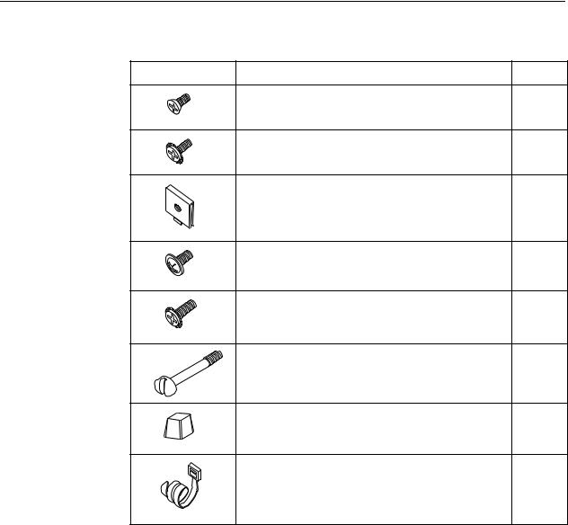
Table 1-3. Contents of Hardware Kit Shipped with the BitStorm 4800 Express
Appearance |
Description |
Quantity |
|
Flat-head screw for attaching 19" mounting brackets to |
6 |
02-17259 |
unit |
|
|
|
|
|
Machine screw with captive starwasher (6-32 x 1/4″) for |
6 |
|
attaching 23" mounting brackets to unit |
|
02-17326 |
|
|
|
Self-retaining nut for racks without threaded holes |
4 |
02-17256 |
|
|
|
Dress screw (12-24 x 1/2″) for use with self-retaining |
4 |
|
nuts |
|
02-17257 |
|
|
|
Machine screw with captive starwasher (10-32 x 1/2″) |
4 |
|
for use with racks with threaded holes |
|
02-17258 |
|
|
|
Captive pan-head screw for replacing long Telco screw |
2 |
02-17325 |
|
|
|
Rubber foot for desk-mount and stacking of units |
4 |
02-17261 |
|
|
|
Cable tie (8″) for strain relief and cable management |
2 |
02-17262 |
|
|
4821-A2-GN21-10 |
July 2004 |
1-5 |

1. Installation
Mounting Configurations
Three basic installation configurations are available:
Rack mount – see Installing the Brackets for Rack Mounting on page 1-6 and Installing the BitStorm 4800 Express Into a Rack on page 1-8.
Wall mount – see Installing the BitStorm 4800 Express on a Wall on page 1-10.
Shelf or desktop – see Installing the BitStorm 4800 Express on a Shelf or Desktop on page 1-12.
Mounting Brackets
Your BitStorm 4800 Express can be installed in a rack or on the wall using mounting brackets. Two brackets suitable for a 19-inch (483 mm) rack (marked EIA-19) and two brackets suitable for a 23-inch (584 mm) Bay Networks or Nortel rack (marked with Paradyne Part Number 868-6282-0020) are shipped with the unit. Two brackets suitable for a 21-inch (535 mm) rack (marked ETSI) are available from Paradyne as a separate feature (see Appendix B, Equipment List).
Rack-mounting brackets may also be used to attach the unit to a wall.
NOTE:
In this guide, the term rack refers to any rack, cabinet, frame, or bay suitable for mounting telecommunications equipment.
Installing the Brackets for Rack Mounting
 Procedure
To install the mounting brackets for rack mounting:
1.Locate the black screw nearest the front panel on each side of the unit, as shown.
CONSOLE |
PORT1 |
|
10/100BT |
1P0ORT2 /100BT
STATUSALARMTEST |
1 |
3 |
5 |
7 |
|
|
|
|
|
|
|
|
|
|
|
|
|
|
9 |
11 13 |
15 17 |
|
|
|
|
|
|
|
|
|
|
|||
2 |
4 |
6 |
|
|
19 21 |
23 |
25 |
27 29 |
|
|
|
|
|
|
||
8 |
10 |
12 14 |
16 18 |
20 22 |
24 |
31 |
33 35 37 |
39 41 |
43 45 |
47 |
||||||
|
|
|
|
|
|
|
|
|
26 |
28 30 |
32 34 |
36 38 |
40 42 |
44 46 |
48 |
|
DSL PORTS 1-24
DSL
POTS 1-24
PORTS 25-48
04-17525
2.Remove these two black screws (one from each side) before attempting to install the mounting brackets.
1-6 |
July 2004 |
4821-A2-GN21-10 |
Loading...