


835 HIP SLED SYSTEM
WARNING:
Read and follow all directions for each step to insure proper assembly of this product.
USER’S GUIDE
CLASS H |
1 |
Version: 835109 |
PART # 7339501 |
|
Revision: 12/09/02 |
REV.B |
|
|
TABLE OF CONTENTS
Safety Statement |
.............2 |
General Notes.................. |
3 |
Tools Required................ |
3 |
Gym Layout..................... |
4 |
Parts list.......................... |
5 |
Assembly Instructions..... |
6-21 |
General Maintenance....... |
22 |
Warranty Statement.......... |
23 |
Product Services.............. |
24 |
Insert-Registration Card |
|
IMPORTANT SAFETY INFORMATION
THERE IS A RISK ASSUMED BY INDIVIDUALS WHO USE THIS TYPE OF EQUIPMENT. TO MINIMIZE RISK FOLLOW THESE RULES!
1.Before using, read all the warnings and instructions on the use of this machine. Use only for intended exercise. DO NOT modify the machine.
2.Obtain a medical exam before beginning any exercise program.
3.Keep body and clothing free of all moving objects.
4.Inspect the machine before use. DO NOT use it if it appears damaged. DO NOT attempt to fix a broken or
jammed machine. Notify your authorized ParaBody dealer before use and have repairs made by an authorized service technician.
5. Be certain that weight pin is completely inserted. Use only the pin provided by the manufacturer. If unsure, call your authorized ParaBody dealer.
6. Never pin the weights or prop plate into an elevated position. DO NOT use the machine if found in this condition. DO NOT attempt to fix. Notify your authorized ParaBody dealer.
7. Inspect cables and their connections before using machine. Pay particular attention to the cable ends. DO NOT attempt to fix. Notify your authorized ParaBody dealer before use and have repairs made by an authorized service technician.
8.Make sure all spring loaded pull pins are fully engaged in the adjustment position and fully tighten thumbscrew before use.
9.Children must not be allowed near this machine. Supervise teenagers.
.
NOTE: In a continual effort to improve our products, specifications are subject to change © 2002 Life Fitness, a division of Brunswick Corporation. All rights reserved. ParaBody is a trademark of Brunswick Corporation
www.parabody.com
2
IMPORTANT NOTES
Please note:
* Thank you for purchasing the ParaBody 835 Hip Sled System. Please read these
instructions thoroughly and keep them for future reference. This product must be assembled on a flat, level surface to assure its proper function.
*This product must be assembled on a flat, level surface to assure its proper function. DO NOT securely tighten any frame connections until the entire frame has been assembled, unless otherwise stated.
Tools Required for Assembly
*3/4” wrench
*9/16” wrench
*Ratchet with 3/4” and 9/16” sockets
*Adjustable wrench
*Tape measure
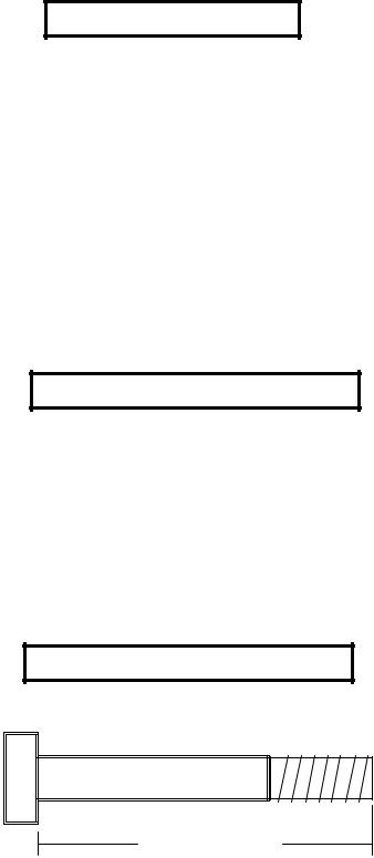
Bolt Length Ruler
NOTE: BOLT LENGTH IS MEASURED FROM THE UNDERSIDE OF THE HEAD OFTHE BOLT.
BOLT LENGTH
BOLT LENGTH RULER:
|
1/2 |
|
1/2 |
|
1/2 |
|
1/2 |
|
1/2 |
|
|
1/2 |
|
|||||||||||
0 |
|
|
1 |
|
|
2 |
|
|
3 |
|
|
4 |
|
|
5 |
|
6 |
|||||||
|
|
|
|
|
|
|
|
|
|
|
|
|
|
|
|
|
|
|
|
|
|
|
|
|
3
1’ |
2’ |
3’ |
4’ |
5’ |
1’
2’
3’
4’
5’
6’
7’
8’
9’
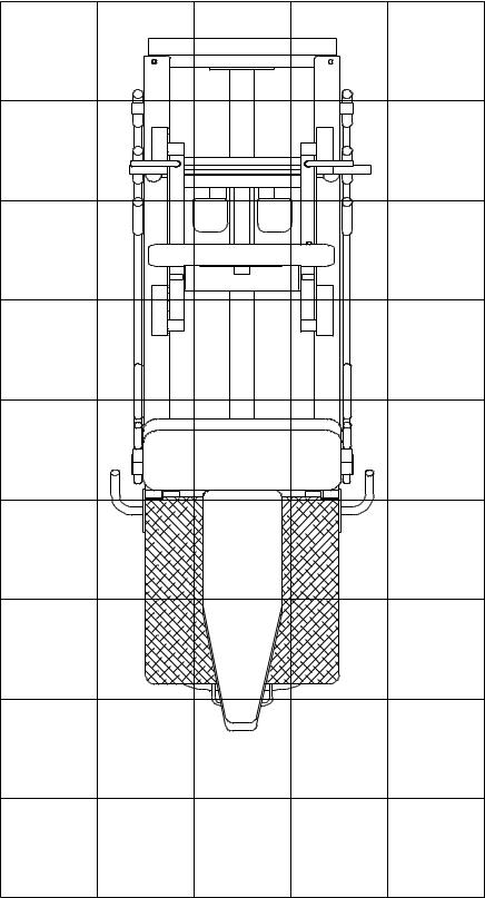
1 Square = 1’ X 1’
4

PARTS LIST
KEY |
PART # |
DESCRIPTION |
QTY |
1 |
LEA6504909 |
BASE |
1 |
2 |
LEA6506809 |
PLATFORM SLEEVE |
1 |
3 |
LEA7337609 |
PAD SUPPORT |
1 |
4 |
LEA6507709 |
RIGHT HANDLE |
1 |
5 |
LEA6507809 |
LEFT HANDLE |
1 |
6 |
LEA6667809 |
REAR UPRIGHT |
1 |
7 |
LEA6505910 |
CARRIAGE STOP BAR |
2 |
8 |
LEA7337309 |
LEFT RAIL |
1 |
9 |
LEA7337409 |
RIGHT RAIL |
1 |
10 |
LEA6504410 |
FOOT PLATE |
1 |
11 |
LEA7337710 |
PLATFORM |
1 |
12 |
LEA6506610 |
PLATFORMADJUSTMENT |
1 |
13 |
LEA6507010 |
WEIGHT SUPPORT |
1 |
14 |
LEA6521210 |
ADJ. WHEEL BRACKET |
2 |
15 |
LEA6534310 |
PAD STOP |
1 |
16 |
LEA6667910 |
CARRIAGE |
1 |
17 |
LEA6509221 |
SHOULDER PAD |
2 |
18 |
LEA6666921 |
SEAT PAD |
1 |
19 |
LEA6667321 |
BACK PAD |
1 |
20 |
LEA6500501 |
3” DIA. WHEEL |
4 |
21 |
LEA6500601 |
2” DIA. WHEEL |
4 |
22 |
LEA3103101 |
1-1/4 X 5” GRIP |
2 |
23 |
LEA3103104 |
1 X 5” GRIP |
2 |
24 |
LEA3116001 |
1-1/4” SQ. RUBBER BUMPER |
2 |
|
|
|
|
KEY |
PART # |
DESCRIPTION |
QTY |
25 |
LEA6270501 |
4 X 14” NON-SKID STRIP |
1 |
26 |
LEA6405201 |
2” SQ. END CAP |
8 |
27 |
LEA6416601 |
1-1/2” X 3/4” PARAGLIDE |
1 |
28 |
LEA7234801 |
2” SQ. COVER CAP |
2 |
29 |
LEA3114403 |
3/8” WASHER |
24 |
30 |
LEA3114502 |
3/8” LOCK WASHER |
8 |
31 |
LEA3114702 |
3/8” LOCK NUT |
8 |
32 |
LEA3114401 |
1/2” WASHER |
32 |
33 |
LEA3114701 |
1/2” LOCK NUT |
14 |
34 |
LEA3235501 |
1/2” LOW HEIGHT LOCK NUT |
8 |
35 |
LEA3235204 |
3/8 X 1” BOLT |
2 |
36 |
LEA3235208 |
3/8 X 2” BOLT |
4 |
37 |
LEA3235212 |
3/8 X 3” BOLT |
8 |
38 |
LEA3235218 |
3/8 X 4-1/2” BOLT |
2 |
39 |
LEA3235405 |
1/2 X 1-1/4” BOLT |
2 |
40 |
LEA3235311 |
1/2 X 2-3/4” BOLT |
2 |
41 |
LEA3235313 |
1/2 X 3-1/4” BOLT |
6 |
42 |
LEA3235316 |
1/2 X 4” BOLT |
2 |
43 |
LEA3235318 |
1/2 X 4-1/2” BOLT |
8 |
44 |
LEA3235320 |
1/2 X 5” BOLT |
2 |
45 |
LEA3110002 |
1-1/4” ROLL PIN |
2 |
46 |
LEA6020601 |
1/2” FLANGE BEARING |
8 |
47 |
LEA6466901 |
1/2” DIA. SPRING PIN |
2 |
|
|
|
|
5
* |
DO NOT SECURELY TIGHTEN |
|
|
AT THIS TIME |
|
6 |
|
|
28 |
|
|
33 |
|
|
32 |
|
|
41 1/2 X 3-1/4” |
|
|
|
1 |
*3/8 X 3” 37 |
|
23 |
|
|
|
29 |
|
|
4 |
26 |
|
|
29 |
31 |
|
|
|
|
* 3/8 X 3” 37 |
5 |
|
FIGURE 1 |
|
|
|
|
|
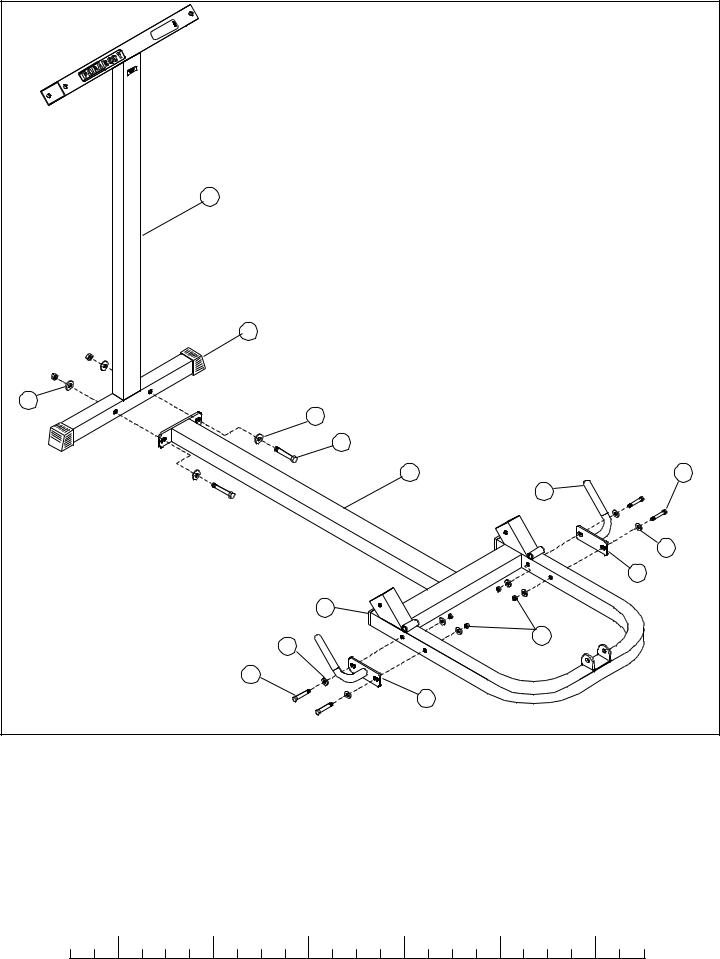
STEP 1:
•SECURELY assemble the REAR UPRIGHT (6) to the BASE (1) as shown in FIGURE 1 using two 1/2 X 3-1/4” BOLTS (41), four 1/2” WASHERS (32), and two 1/2” LOCK NUTS (33).
•LOOSELY assemble the RIGHT (4) and LEFT HANDLES (5) to the BASE (1) on their respective sides using four 3/8 X 3” BOLTS (37), eight 3/8”WASHERS (29), and four 3/8” LOCK NUTS (31) (DO NOTSECURELY TIGHTENATTHISTIME)
|
1/2 |
|
1/2 |
|
1/2 |
|
1/2 |
|
1/2 |
|
|
1/2 |
0 |
1 |
2 |
3 |
4 |
5 |
6 |
||||||
6
|
44 1/2 X 5” |
1 |
46 |
|
|
|
11 |
46 |
33 |
|
|
44 1/2 X 5” |
|
FIGURE 2 |
|
STEP 2:
•Insert four 1/2” FLANGE BEARINGS (46) into the BUSHINGS on the BASE (1), and four 1/2” FLANGE BEARINGS (46) into the BUSHINGS on the PLATFORM (11) as shown in FIGURE 2.
•Assemble the PLATFORM (11) between the BUSHINGS on the BASE (1) as shown in FIGURE 2 using two 1/2 X 5” BOLTS (44) and two 1/2” LOCK NUTS (33). (TIGHTEN THE CONNECTION ENOUGH TO REMOVE THE PLAY, YETALLOWING
THE PLATFORM TO ROTATE FREELY)
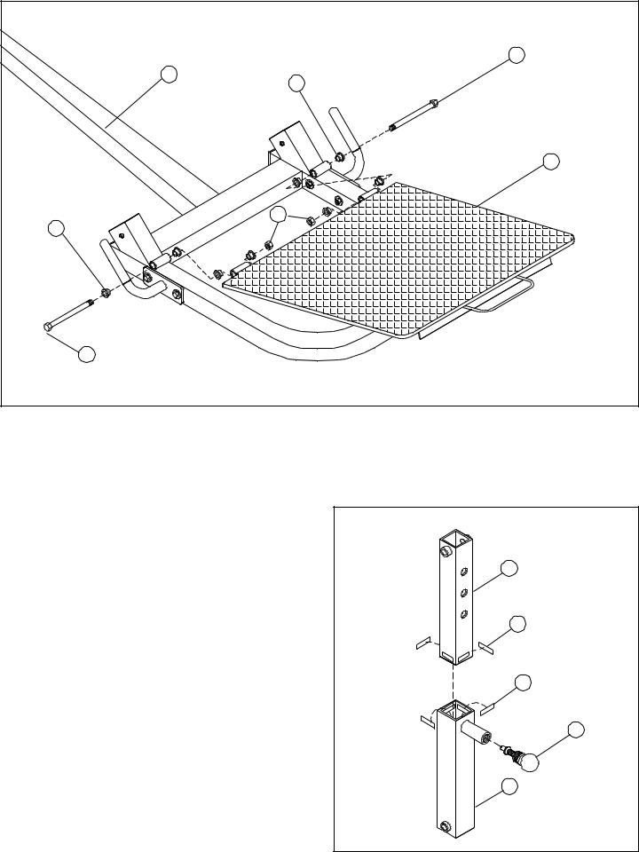
STEP 3: |
12 |
|
• Attach four 1-1/2 X 3/4” PARAGLIDE STRIPS (27) to the end of |
|
|
the PLATFORM ADJUSTMENT (12), and four 1-1/2 X 3/4” |
|
|
PARAGLIDE STRIPS (27) to the end of the PLATFORM SLEEVE |
27 |
|
as shown in FIGURE 3 using the following steps: |
||
|
||
• Thoroughly clean all surfaces where the PARAGLIDE |
|
|
STRIPS (27) are to be attached. |
27 |
|
|
•Remove the PARAGLIDE STRIPS (27) from the paper backing and firmly apply them to all shown surfaces.
47
• SECURELY Assemble one 1/2” DIA. SPRING PIN (47) to the SPRING PIN HOUSING, on the PLATFORM SLEEVE (2) as
shown in FIGURE 3. (!!! IMPORTANT !!! TIGHTEN THE 2
NUT OF THE SPRING PIN SECURELY)
FIGURE 3
7
|
1/2 X 4” 42 |
|
|
11 |
|
|
12 |
|
|
47 |
|
|
1/2 X 4” 42 |
|
|
33 |
|
|
2 |
|
|
1 |
|
SECURELYTIGHTEN |
|
|
HANDLES BOTH SIDES |
33 |
|
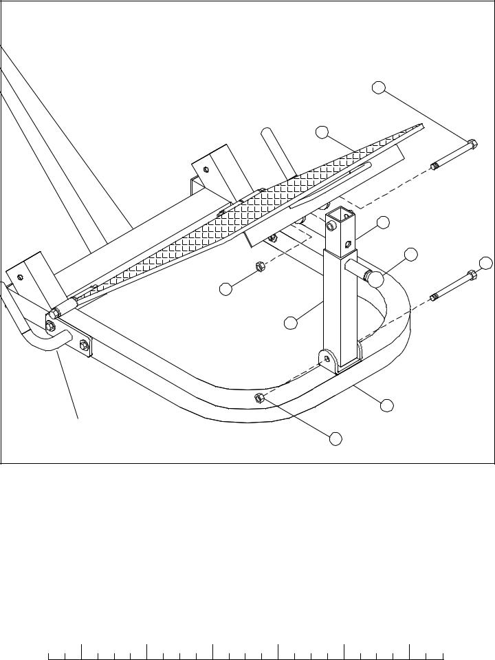
FIGURE 4 |
||
|
STEP 4:
•Assemble the PLATFORM SLEEVE (2) to the BASE (1) as shown in FIGURE 4 using one 1/2 X 4” BOLT (42), and one 1/2” LOCK NUT (33). (TIGHTEN THE CONNECTION ENOUGH TO REMOVE THE PLAY, YETALLOWING THE PLAT-
FORM SLEEVE TO ROTATE FREELY)
•Pull back the 1/2” DIA. SPRING PIN (47) on the PLATFORM SLEEVE (2) and insert the PLATFORM ADJUSTMENT (12) into it. Slide the PLATFORM ADJUSTMENT (12) down to the first adjustment hole and release the SPRING PIN (47).
•Assemble the PLATFORM ADJUSTMENT (12) to the PLATFORM (11) as shown in FIGURE 4 using one 1/2 X 4” BOLT (42), and one 1/2” LOCK NUT (33). (TIGHTEN THE CONNECTION ENOUGH TO REMOVE THE PLAY, YET ALLOWING
THE PLATFORM ADJUSTMENT TO ROTATE FREELY)
|
1/2 |
|
1/2 |
|
1/2 |
|
1/2 |
|
1/2 |
|
|
1/2 |
0 |
1 |
2 |
3 |
4 |
5 |
6 |
||||||
8
 Loading...