


950 st
Serious Steel
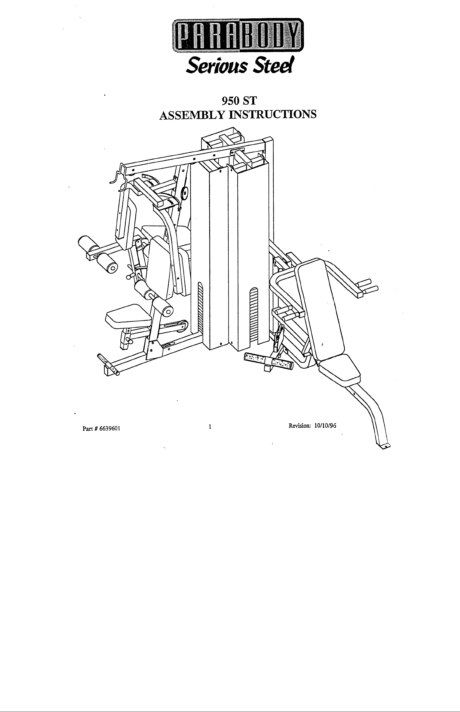
950 ST
ASSEMBLY INSTRUCTIONS
Pa.rt # 6639601
R~vision: 10/10/96

***IMPORTANT***
THE pARABODY 950 ST MUST BE ASSEMBLED ON A FLAT, LEVEL SURFACE TO ASSURE ITS PROPER
¯
FUNCTION.
PARABODY INC. STRONGLY RECOMMENDS THAT THIS PRODUCT BE ASSEMBLED B~( TWO PERSONS TO
AVOID" POSSIBLE INJURY.
¯
KEEP ALL FRAME CONNECTIONS LOOSE, UNTIL INSTRUCTED IN THE ASSEMBLY STEP SEQUENCES TO
SECURELY TIGHTEN. ~
¯
IF YOU EXPERIENCE ~IY PROBLEM WITH THE ASSEMBLY OF THIS PRODUCT, PLEASE CONTACT YOUR
DEALER OR YOUR PARABODY CUSTOMER SERVICE REPRESENTATIVE AT: 1-800-328-9’714
¯
TOOLS REQUIRED,: RATCHET, 3/4 SOCKET or WRENCH, 9/16 SOCKET or WRENCH, 7/16 SOCKET or
WRENCH, ADJUSTABI,E WRENCH, 1/8 ALLEN WRENCH, 5/32 ALLEN WRENCH, 7/32 ALLEN WRENCH, LEVEL,
and RUBBER MALLET or HAMMER
2
IliA
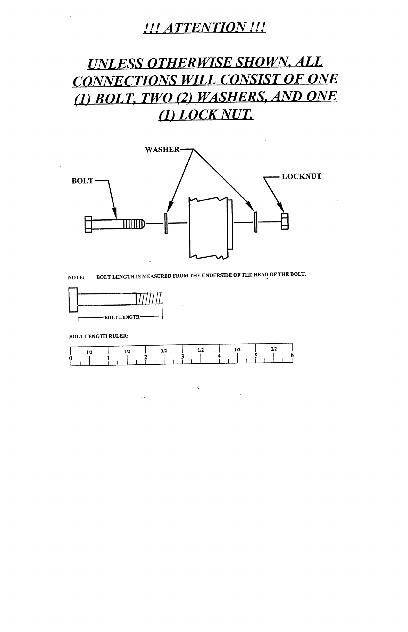
TTENTION . !!
~
(1) B O L I; TWO (2) ~ WASHERS. AN_D__ONE
-- LOCKNUT
NOTE: BOLT LENGTH IS MEASURED FROM THE UNDERSIDE OF THE HEAD OF THE BOLT.
,1,3///ii!!1
BOLT LENGTH
BOLT LENGTH RULER:
1
2
3
4 [ I I I
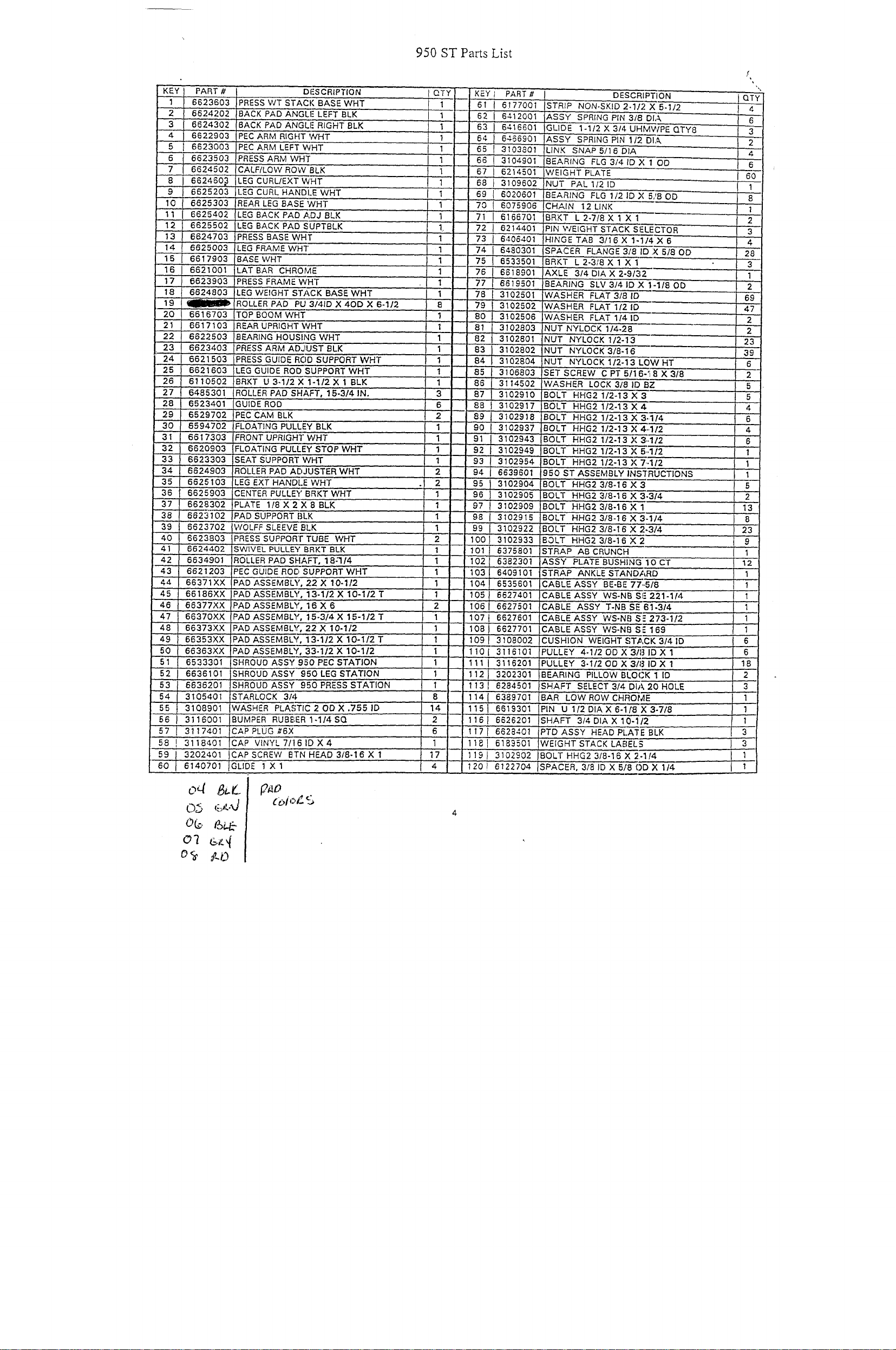
950 ST Pacts List
KEY} PART# DFSCRIPTION
II 6623603 PRESS WT STACK BASEWHT
2 I 6624202 BACK’ PAl) ANGLE LEFTBLK
3..I 662’4302 BACK PADANGLFRIGHTBLK
4
I 6622903
5
I 6623003
6
t 6’623503
I 6624502
" ~
8
I 662460,3 LEG CURL/EXTWHT
" ~
} 6625203 LEG CURL HANDLEWHT
.10
I ’6~25303
11 I 6625402
12 662550~ LEG BACK PADSUPTBLK
13 6624703 PRESSBASEWHT
14 6625003 !LEG FRAME WHT
15
6617903 ’BASEWHT
16 6621001 LATBAR CHROM~
17 6623903 PRESS FRAMEWHT
’18 6824803
19
~~-
20 6616703 TOP BOOM WHT
"2’1 6617103 REAR UPRIGHTWHT’
22 6822503 BEARING HOUSINGWHT
23
6623403 PRESS ARM ADJUSTBLK
24 6621503 PRESS GUIDE ROD suPPORT WHT
’"25 6621603 LEG GUIDE ROD SUPPORTWHT
..... 26
61’10502 BRKT’0 3-1/2X 1-1/2X 1 BLK
27 6485301 ROLLER PAD SHAFT, 15-3/4 IN.
"28 6523401 GUIDE’ROD
29
6529702 PECCAM BLK
30 6594702 F~’OATING PULLEY BLK
31 6617303 FRONT UPRIGHT’V~’HT
32 6620903 FLOATING PULLEY STOP WHT
33 6623303 ;SEAT sUPPORTWHT
34 6624903
35
6625103 LEGEXTHANDLEWHT
36 662~903 CENTER PULLEYBRKTWHT
37 6628302
38
66231’52 PAD’SUPPORTBLK
’:~9 6623702
40
6623803 PRESS SUPPORT TUBE WHT
41 6624402 SWIVEL PULLEY BRKT BLK
42 6634901 ROLLER PAD SHAFT, 18-’I14
~,3 662i203 PEC GUIDE Ror~ SUPPORT Writ
44 66371XX
45
66186XX PAD ASSEMBLY, 13-1/2X 10-1/2T
46
66377XX P~DASSEMBLY, 16X6
47 66370XX
48 66373Xx
49 66353XX iPADASSEMBLY, 13-1/2X 1"0-1/2T
50
66363XX ~I~A’D ASSEMBLY,33-1/2 X 10-1/2
51 6533301 ;SHROUDASSY950PECSTAO;ION
52
6636101 SHROUDASSY’ 950 LEGS~ATION
53 6636201 SHROUD ASSY’" 950 PRESS STATION
54 3105401 STARLOCK’ 3’I4
¯ ~5
3108901
56 I 31i6’001 BUMPER RUBBER I-I/4SQ
’ ~7 I 3117401
58 ! 3118401’
59 I 3202401 iCAPSCREW BTNHEAD3/8~I6X’1
6’0} 6140701 IGLIDE lXl , , ii
PECARM RIGHTWHT
PECARM LEFTWHT
PRESS AR/Vl WHT
CALF/LOW RQW 8LK
REAR LEG BASEWHT
LEG BACK PADADJBLK
LEG WEIGHT STACK BASEWHT
. ROLLER PAD PU 3/41D X 4OD X 6-1/2
ROLLER PAD Ar~JUSTER WHT
PLATE 1’18 X 2 X 8 BLK
WOLFF SLEEVE’ BLK
PAD ASSEMBLY, 22X 10-1/2
PAD ASSEMBLY,
PAD ASSEMBLY, 22X 10-1/2
WASHER PLASTIC2ODX.’~551D
CAPPLUG#6X
(~AP VINY~7/’I61D’X4
]5-3/4 X 15-1/2 T
I QTY
1
1
1
1
I
I
I
2
2
2
6
14
2
6
17
4
KEY I PART #
61 i 6117700
"62 i 6412O01
63 ! 6416601 GLIDE 1-1/2X3/4UHilWPEQTY8
64 I 6466901 ASSY SPRING PIN i/~DIA
65 ! ~103801 LINK SNAP B/16DIA
66 .~ 3104901
67I 6214501
68 } 3109602 NUT PAL 1121D
69 I 6020601
70 ’i 6075906
71 ,{ 6166701 BRKT L2-71BX 1 X 1
72 I 6214’401
73 ! 6406401 HINGE TAB 3/16X 1-1 X6
74 I 6480301
75 I 6533501 BRKT L2-3/BX 1 X 1
76 6618901
7~ , 6619501
78 I 3102501
79 I 31025o2
BO I 3102506
81 3102803
3102801
83 j 3102802 NUT
84.I 3102804 NUT
85 3106803
86
3114502
87 3102~10
88 I 3102917
89t 5~o2918
90
3102937 BOLT HHG2 1/2-13X4.,112
I,
91I3102943 BOLT
92I,3102949
93
3102954 BOLT
I
94 ! 6639601 950 ST ASSEMBLYINS’f’RUCTIONS
95I3102904
96
3102905 BOLT HHG23/8-16X3
I
97t3102909 ~BOLT HHG23/8-16X1
98 I 3102916 BOLT HHG2 3/8-16X3 /4
99 I 3102922 BOLT HHG23/8-161~’2 ~/4
1001 310293’3 BOLT HHG2 3/8-16X2
101 I 6375801
1021 6382301 ASSY PLATE BUSHING OCT
1031 6409101 STRAP ANKLESTAND~,RD
104II6535601 CABLE ASSY BE-BE 77..
105 I 6627~,0i CABL~E ASSY WS-NB SI! 221-1/4
1061 6627501
107l 6627601
08J 6627701
091 3108002
1101 3116101
1111 311620i
1121 3202301
113l 6284501
114l 638970i
1151 6619301
1161 6626201
117!.6628401
1181 6183501
119} 3102902
120i 6122704
’STRIP NON-SKID 2-1)2 X 5-1/2
ASSY SPRING PIN 3/8
BEARING FLG3/41DX 1
WEIGHT PLATE
BE’ARING FLG 1/21DX 5/8OD
CHAIN 12LINK ’
PIN V/EIGHT STACK SE.ECTOR
SPACER FLANGE 3/8 II ,XS/8OD
AXLE 3/4DIAX2"9/~-;
BEARING SLVO/41DX 1-1/8OD
WASHER FLAT 3/81D
WASHER FLAT 1/2 ID
;WASHER FLAT 1(41D
NUTNYLOCK 1/4-28
NUT NYLOCK 1/2-13
NYLOCK3/8-16
NYLOCKl/2-i3LOWHT
SET SCREW CPT5/16. 8X3/8
WAS’HER" LOCK 318 ID BZ
BOLT
HHG2 1/2-13X
BOL’[: HHG2 1/2-i3x4
BOLT HHG2 1/2-i3 X 3..1/4
HHG2 1/2-13X3,,112
BOLT HHG21/2-13X5
HHG2 1/2-13 X7..1/2
BOLT HHG2 3/8-16X
STRAP ABCRUNCH
CABLE ASSY T-NB’SE 61-3/4
CABLE ASSY WS-NB S:" 273-1/2
CABLE ASSY WS-NB S 169
CUSHION WEIGHT STA, 3/4 ID
PULLEY 4-1/20DXO/81DX 1
PULLEY 3-1/200X3181DX 1
BEARING PILLOW BLO~: 1 ID
SHAFT SELECT 3/4 DIA 20 HOLE
BAR LOW ROW CH~O’M
PIN U 1/2 OlA X 6-1/8’~ 3-7/8
SHAFT 3i4 DIA X 10-1/:
PTD ASSY HEAD PLATE BLK
:WEIGHT STACK LABELS ] 3
BOLT HHG23/8-16X2. /4
ISPACER, 318 ID X 5I~()[ X 1/4 J 1
DE~CRi TION
/2
8
1
2
3
4
28
3
1
2
, 69
47
2
2
23
39
6
2
5
5
4
’6
’4
6
’1
1
1
1
I 1
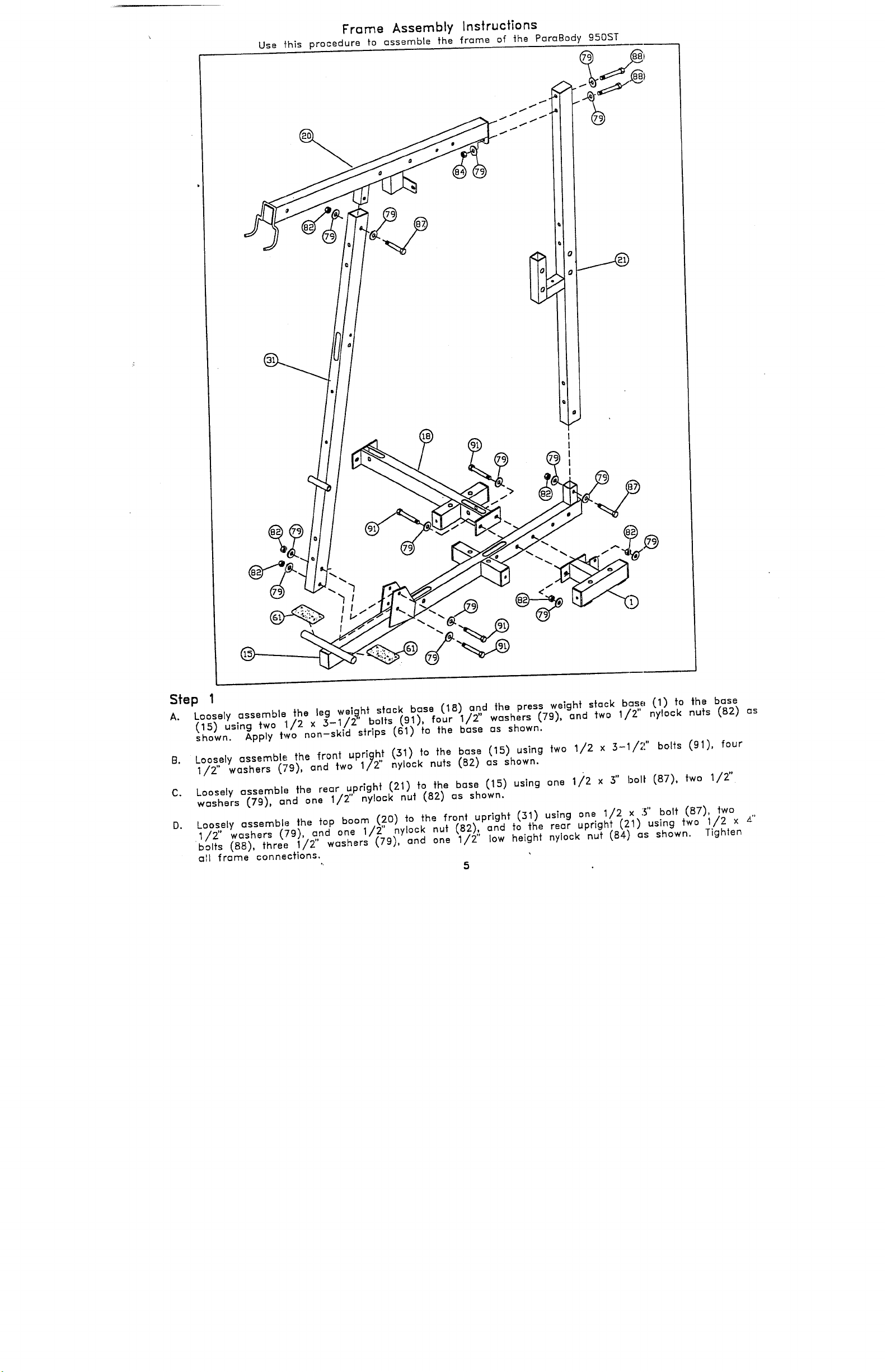
Frame Assembly Instructions
Use t’his procedure to ossemble the frame of the PareBody 950ST
Step 1
Loosely assemble the leg wei.~,ht stack bose (18) a.n,,d the press weight s~ack base (1) to the
A.
(15) using two 1/2 x .3-1/2 bolts (91), four 1/2 washers (79), and two 1/2" nylock nuts (B2)
~ho~n. Apply two non-skid s~rips (61) fo the base as shown.
Loosely assemble the front uprig~ (31) to the base (15) using two 1/2 x 3-1/2" bolts (91),
B.
1/2’ washers (79), and two 1/2 nylock nuts (82) as shown.
3"
Loosely ~ssembe the re~r ~,prighf (21) fo the b~se (15) using one li2 x bolt (87),
C.
w~shers (79), ~nd one 1/2 nyock nul (82) ~s shown.
D. Log~ly a,
1/Z wesners k~~},_~,
~1 frame connections.
ssembl: the fop boom (20) ~o fh~ front upright (31) using one 1/2 x 3" bolt (BT),
,’;~ --- --- ~/2" nvlock nut {82), and to the rear uprigh~ (~1) using two 1/2 x
u~
~’~ "~-_.. ~.~ ~/~,, low height nylock nut ~84) ~s shown.
5
/2"
Tighten
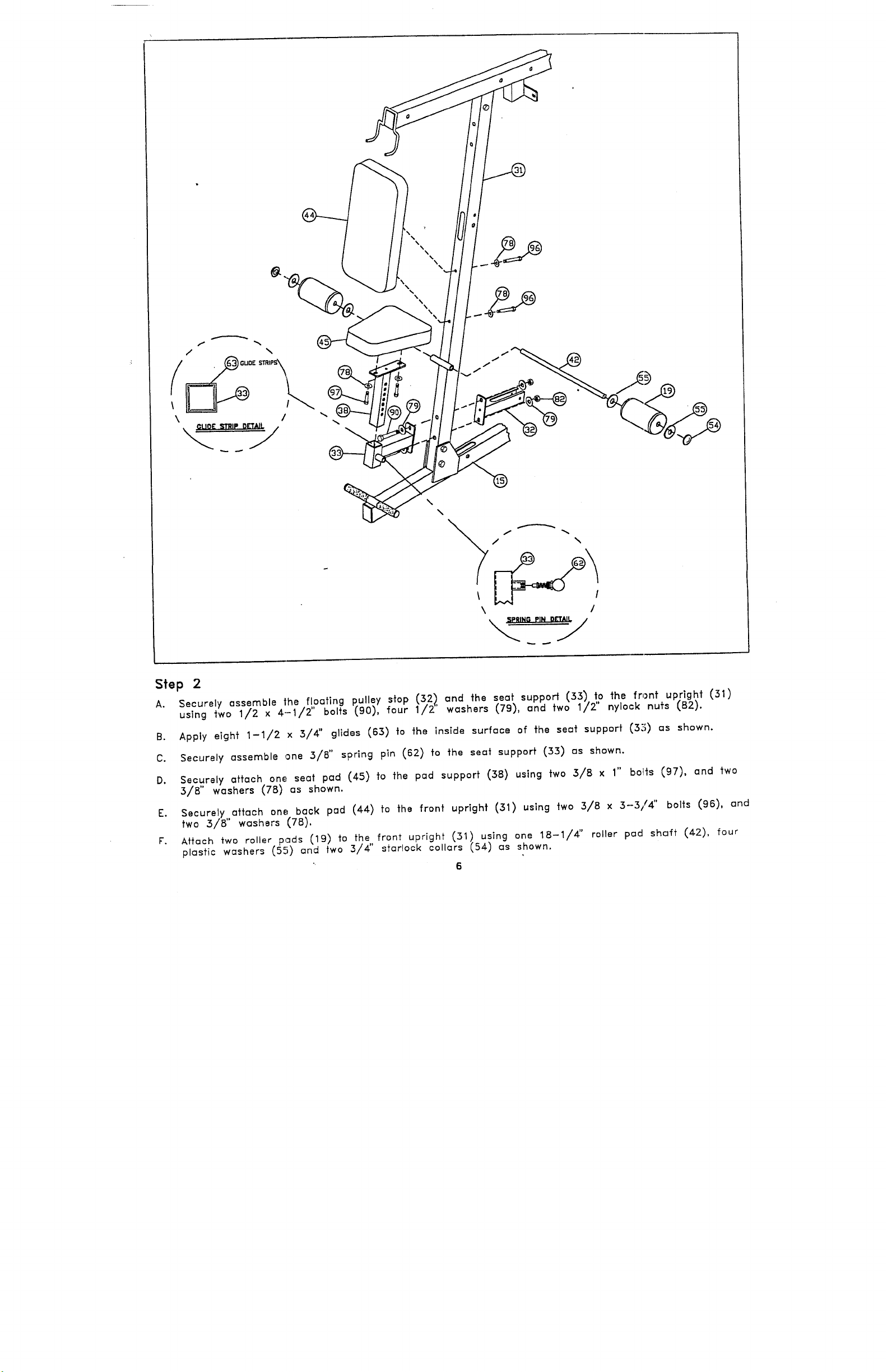
Step 2
Securely assemble the floating pulley stop (:52), and the s.eat support (33) to the front upright
A.
using two 1/2 x 4.-1/2" bolts (90), four 1/2’ washers (.79), and two 1/2" nylock nuts (B2).
Apply eight 1-1/2 x 3/4" glides (63) to the inside surface of the seat support (32;) as shown.
B.
Securely assemble one 3/8" spring pin (62) to the seat support (33) os shown.
C.
Securely attach one, seat pad (45) fo the pad support (38) using two 3/8 x bolts (97), and
D.
3/8" washers (78) as shown.
Securely attach one; back pad (44) to the front upright (31) using two 3/8 x 3--3/4" bolts (96),
E.
two 3/8" washers (78).
Attach two roller pads (19) to the front upright (51) using one 18-1/4" roller pad shaft (42),
F.
plastic washers (5.~) an two
="
d
3/4" sfarlock collars (54) as shown.
6
1"
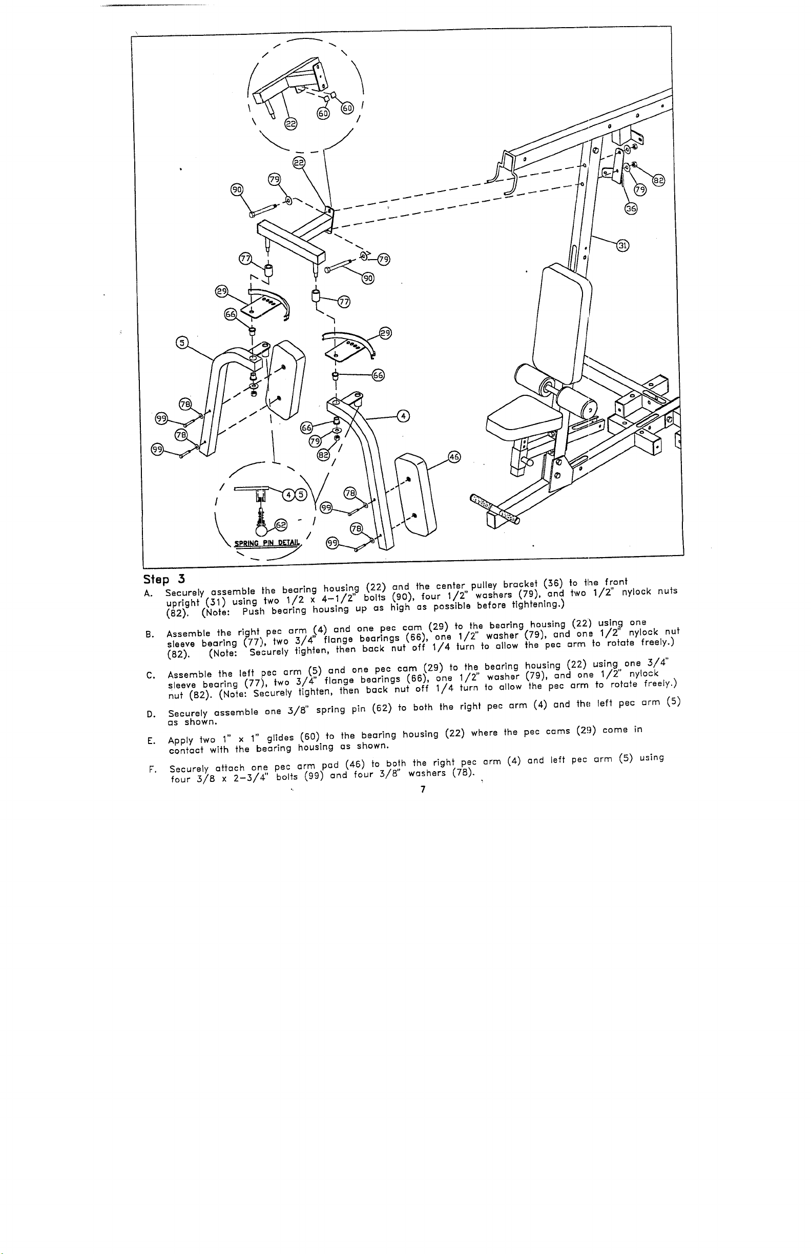
Step 3
Securely assemble the bearing housl.n,g (22) and the center, pulley bracket (36) to fine front
A.
upright (31) using two 1/2 x 4-1/2’ bolts (90), four 1/2’ washers (79), and two 1/2" nylock
(82). (Note: Push bearing housing up as high as possible before tightening.)
Assemble the right, pee arm ,I4) and one pec cam (29) to the bearing housing (22) using
B.
sleeve bearlng (77), two 3/4 flange bearings (66), one 1/2" washer (79), and ona 1/2" nylock
(82). (Note: Securely tighten, then back nut off 1/4 turn to allow the pec arm to rotate freely.)
Assemble the left pec arm (5) and one pec cam (29) to the bearing housing (22) using 3/4"
C.
sleeve bearing (77), two 3/4" flange bearings (66), 1/2" washer (79), and on e 1/ 2" n ylock
nut (B2). (Note: Securely tighten, then back nut off 1/4 turn to allow the pec arm to rotate freely.)
Securely assemble one 3/8" spring pin (62) to both the right pec arm (4) and the left pec arm
D.
as shown.
1"
E. Apply two 1" x
contact with the bearing housing as shown.
Securely attach one pec arm pad (46) to both the right pec arm (4) and left pec arm (5)
F.
glides
(60) to the bearing housing (22) where the pec cams (2!))
four 3/8 × 2-3/,~" bo~ts (99) and four 3/8" washers (78).
7
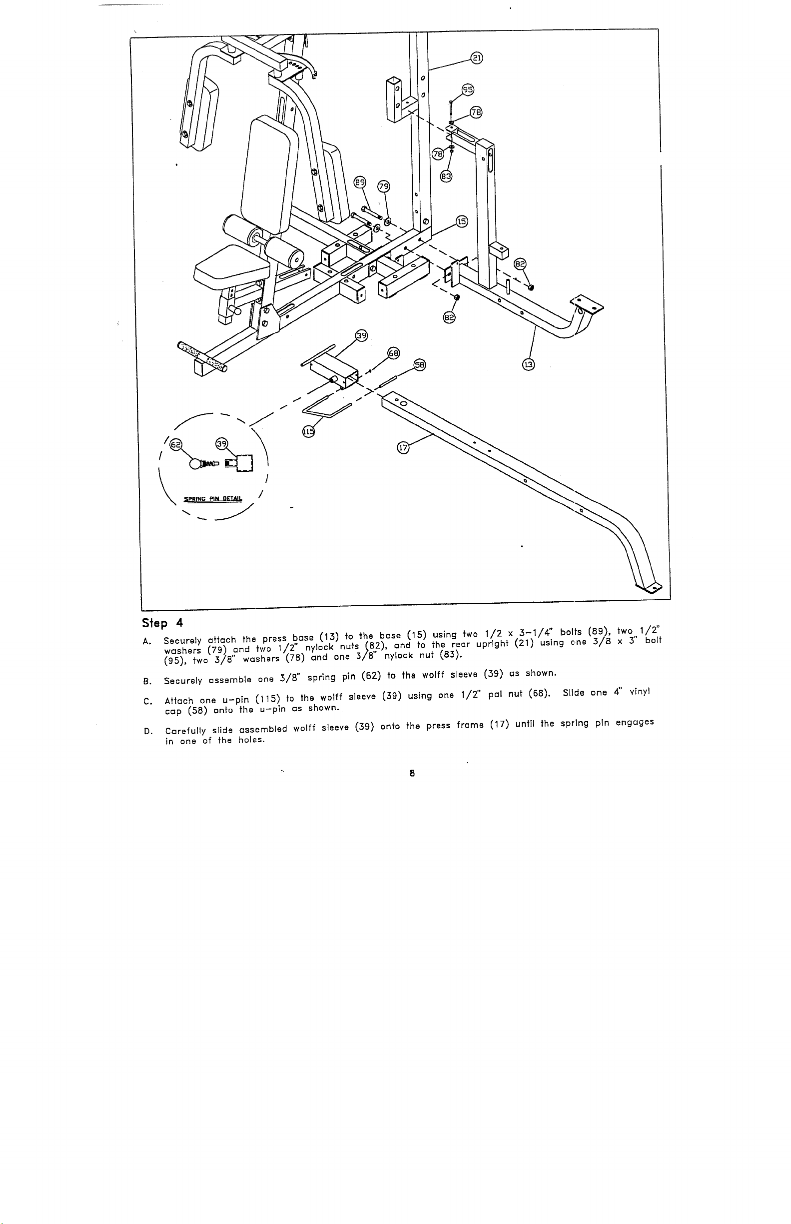
Siep 4 /2"
Securely attach fh~, press base (13) fo the base (15) using two 1/2 x 3-1/4" bolts (89),
A.
washers (79) ,~nd two 1/.2".nylock nuts .(8,2), and fo the rear upright (21) using one 3/8 x 3"
(95), two 3/8’ washers (,78) and one 3/8’ nylock
Securely assemble one :~/B" spring pin (62) to the wolff sleeve (39) as shown.
B.
Aftc~ch one u-pin (115) to the wolff sleeve (39) using one 1/2" pal nut (68). Slide
C.
cap (58) onto the u-pin as shown.
Cc~refully slide assembled wolff sleeve (39) onto the press frc~me (17) until the spring pin engages
D.
in one of the holes.
vinyl
 Loading...