


S2J
PANJIT S2J, S2B, S2D, S2G, S2K Datasheet
...
S2A THRU S2M
FEATURE
S
MECHANICAL DATA
MAXIMUM RATINGS AND ELECTRICAL CHARACTERISTIC
S
SYMBOLSS2AS2BS2DS2GS2JS2KS2MUNITS
RRM
Volts
RMS
Volts
D
C
Volts
(AV
)
s
FSM
s
F
R
R
R
J
P
W
STG
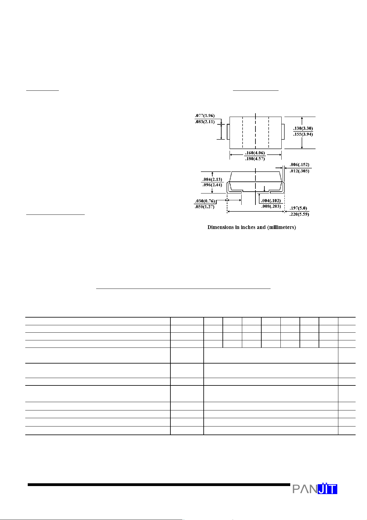
SMB/DO-214A
A
SURFACE MOUNT RECTIFIER
VOLTAGE - 50 to 1000 Volts CURRENT - 2.0 Amperes
l
For surface mounted applications
l
High temperature metallurgically bonded-no
compression contacts as found in other
diode-constructed rectifiers
l
Glass passivated junction
l
Built-in strain relief
l
Easy pick and place
l
Plastic package has Underwriters Laboratory
Flammability Classification 94V-O
l
Complete device submersible temperature of
260 ¢J for 10 seconds in solder bath
Case: JEDEC DO-214AA molded plastic
Terminals: Solder plated, solderable per MIL-STD-750,
Method 2026
Polarity: Indicated by cathode band
Standard packaging: 12mm tape (EIA-481)
Weight: 0.003 ounce, 0.093 gram
Ratings at 25¢J ambient temperature unless otherwise specified.
Single phase, half wave, 60 Hz, resistive or inductive load.
For capacitive load, derate current by 20%.
Maximum Recurrent Peak Reverse Voltage V
Maximum RMS Voltage V
Maximum DC Blocking Voltage V
Maximum Average Forward Rectified Current,
at TL=110
¢J
Peak Forward Surge Current 8.3ms single half sine-
I
I
wave superimposed on rated load(JEDEC method)
Maximum Instantaneous Forward Voltage at 2.0A V
Maximum DC Reverse Current TA=25¢J
At Rated DC Blocking Voltage TA=125
¢J
I
Maximum Reverse Recovery Time (Note 1) T
Typical Junction capacitance (Note 2) C
Typical Thermal Resistance (Note 3)
R£KJL
Operating and Storage Temperature Range TJ,T
NOTES:
1. Reverse Recovery Test Conditions: IF=0.5A, IR=1.0A, Irr=0.25A
2. Measured at 1 MHz and Applied Vr=4.0 volts
3. 8.0mm2 (.013mm thick) land areas
50 100 200 400 600 800 1000
35 70 140 280 420 560 700
50 100 200 400 600 800 1000
2.0 Amp
60.0 Amp
1.10 Volts
5.0
125
2.5 £g
30.0
16 ¢J
-55 to +150 ¢J
£g A
S
F
/
 Loading...