


Color Monitor
Operating Instructions
Model No. WV-CM2080
WV-CM1780
WV-CM1480
ENGLISH
POWER |
|
|
|
|
|
ON |
STANDBY INPUT |
MENU |
|
|
2080 |
OFF |
SELECT |
Video |
Monitor |
||
|
|
|
|||
|
|
|
|
WV-CM |
|
Before attempting to connect or operate this product,
please read these instructions carefully and save this manual for future use.
FRANÇAIS
ENGLISH VERSION
CONTENTS |
|
PREFACE .................................................................................................................................................... |
3 |
FEATURES .................................................................................................................................................. |
3 |
PRECAUTIONS ........................................................................................................................................... |
3 |
MAJOR OPERATING CONTROLS AND THEIR FUNCTIONS .................................................................... |
4 |
INSTALLATION ........................................................................................................................................... |
6 |
CONNECTIONS .......................................................................................................................................... |
7 |
SETUP PROCEDURES ............................................................................................................................... |
9 |
OPERATING PROCEDURES ...................................................................................................................... |
11 |
OPERATING PROCEDURES (with the System Controller) ......................................................................... |
14 |
APPENDIX .................................................................................................................................................. |
15 |
SPECIFICATIONS ....................................................................................................................................... |
17 |
ACCESSORIES ........................................................................................................................................... |
18 |
CAUTION
RISK OF ELECTRIC SHOCK
DO NOT OPEN
CAUTION: TO REDUCE THE RISK OF ELECTRIC SHOCK,
DO NOT REMOVE COVER (OR BACK).
NO USER-SERVICEABLE PARTS INSIDE.
REFER SERVICING TO QUALIFIED SERVICE PERSONNEL.
|
The lightning flash with arrowhead sym- |
|
|
bol, within an equilateral triangle, is |
|
|
intended to alert the user to the pres- |
|
|
ence of uninsulated "dangerous voltage" |
|
|
within the product's enclosure that may |
|
SA 1965 |
be of sufficient magnitude to constitute a |
|
risk of electric shock to persons. |
||
|
The exclamation point within an equilateral triangle is intended to alert the user to the presence of important operating and maintenance (servicing) instructions in the literature accompanying the appliance.
SA 1966
For U.S.A
NOTE: This equipment has been tested and found to comply with the limits for a Class A digital device, pursuant to Part 15 of the FCC Rules. These limits are designed to provide reasonable protection against harmful interference when the equipment is operated in a commercial environment. This equipment generates, uses, and can radiate radio frequency energy and, if not installed and used in accordance with the instruction manual, may cause harmful interference to radio communications.
Operation of this equipment in a residential area is likely to cause harmful interference in which case the user will be required to correct the interference at his own expense.
FCC Caution: To assure continued compliance, (example - use only shielded interface cables when connecting to computer or peripheral devices). Any changes or modifications not expressly approved by the party responsible for compliance could void the user’s authority to operate this equipment.
The serial number of this product may be found on the rear of the unit.
You should note the serial number of this unit in the space provided and retain this book as a permanent record of your purchase to aid identification in the event of theft.
Model No.
Serial No.
WARNING:
To reduce the risk of fire or electric shock, do not expose this appliance to rain or moisture.
2

PREFACE
The Panasonic WV-CM2080, WV-CM1780 and WV-CM1480 Color Monitor’s high resolution S-video input assures high definition picture quality.
All monitor functions, except for power and input selection, can be controlled from an onscreen menu. Provided with power saving feature as well as standard BNC and S-video input connectors for connection to CCTV equipment.
The WV-CM2080, WV-CM1780 or WV-CM1480, and other devices compatible with Panasonic Security Data mode the bear logo 


 .
.
FEATURES
•Approx. 508 mm (20-inch) viewable area with a horizontal resolution of 500 TV lines (WV-CM2080)
•Approx. 406 mm (16-inch) viewable area with a horizontal resolution of 800 TV lines (WV-CM1780)
•Approx. 356 mm (14-inch) viewable area with a horizontal resolution of 750 TV lines (WV-CM1480)
•Three selectable inputs, including two composite and one S-video input
•Two standby modes for power saving: lower display brightness and blackout
•Maximum speaker output of 0.7 W
•The monitor can be controlled with the specified system controller using PS•Data (Panasonic Security Data) mode.
•Onscreen Setup menu
•Supplied with rack mounting brackets for mounting in a rack (WV-CM2080)
ENGLISH
PRECAUTIONS
•Refer all work related to the installation of this product to qualified service personnel or system installers.
•Do not block the ventilation opening or slots on the cover.
To prevent the appliance from overheating, place it at least 5 cm (2 inches) away from the wall.
•Do not drop metallic parts through slots.
This could permanently damage the appliance. Turn the power off immediately and contact qualified service personnel for service.
•Do not attempt to disassemble the appliance.
To prevent electric shock, do not remove screws or covers.
There are no user-serviceable parts inside. Contact qualified service personnel for maintenance.
•Handle the appliance with care.
Do not strike or shake it, as this may damage the appliance.
•Do not expose the appliance to water or moisture, nor try to operate it in wet areas.
Take immediate action if the appliance becomes wet. Turn the power off and refer servicing to qualified service personnel. Moisture may damage the appliance and also cause electric shock.
•Do not use strong or abrasive detergents when cleaning the appliance body.
Use a dry cloth to clean the appliance when it is dirty. When the dirt is hard to remove, use a mild detergent and wipe gently. Afterwards, wipe off the remained part of the detergent in it with a dry cloth.
•Do not operate the appliance beyond its specified temperature, humidity or power source ratings.
Use the appliance at temperatures within –10°C - +50°C (14°F - 122°F) and a humidity below 90 %.
The input power source for this appliance is 120 V AC 60 Hz.
3
MAJOR OPERATING CONTROLS AND THEIR FUNCTIONS
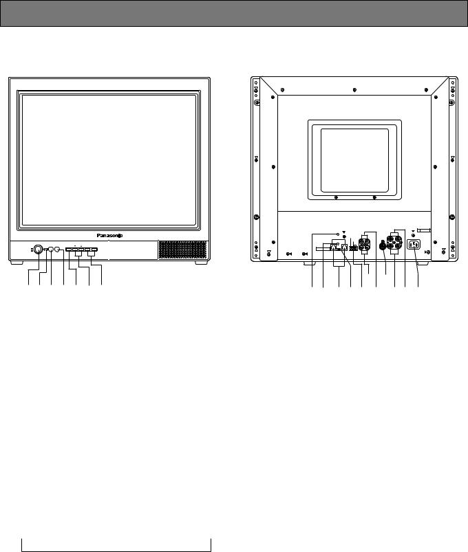
● Front View |
● Rear View |
Video Monitor WV-CM 2080
POWER |
|
INPUT |
|
|
STANDBY |
SELECT |
MENU |
– AUDIO+ |
|
ON |
|
|
|
|
OFF |
|
|
|
|
qw e r t y u
FOCUS |
|
AUDIO |
|
|
B VIDEO |
A |
|
|
|
A |
|
IN |
IN |
|
|
|
|
B |
|
|
|||
DATA |
STANDBY |
IN |
IN |
S-VIDEO |
|
|
|
ON |
|
|
|
|
|
||
|
STANDBY |
|
|
|
|
|
|
|
OFF |
|
|
|
|
|
|
|
G |
|
|
|
|
|
|
P S ·D a t a |
|
|
|
IN |
OUT |
OUT |
AC IN |
ON OFF |
|
OUT OUT |
|||||
|
|
|
|
|
|||
TERMINATION |
|
|
|
|
|
|
|
|
|
!7!8 |
|
||||
!1!2!3!4!5!6@0!9@1 |
|||||||
* The above figures represent model WV-CM2080.
qPower Button (POWER ON/OFF)
This button turns the power of the monitor on and off.
wPower Indicator
Is on when the power of the monitor is turned on, also in standby mode.
On: Green light Standby: Orange light
eStandby Button (STANDBY)
Pressing this button toggles the display mode on the monitor screen as shown below.
On: Normal display
Standby (Mode 1): Low display brightness Standby (Mode 2): No display (blackout)
rInput Selection Button (INPUT SELECT)
Selects input in the sequence shown below.
 VIDEO IN A
  VIDEO IN B
  S-VIDEO IN

tMenu Button (MENU)
Pressing this button opens the Display Setting menu for changing the monitor’s display settings.
Pressing this button for 5 seconds or more opens the COMMUNICATION SETUP menu.
yDirection Button (C, D)
These buttons move the cursor to the item parameters in the Display Setting and Setup menus.
C: Down D: Up
uDecrement/Increment Button (AUDIO -, +)
Press these buttons to increase or decrease the audio volume.
These buttons also select the item parameter or level in the Display Setting and Setup menu.
!1Focus Control (FOCUS)
This control adjusts the screen focus.
!2Screen Control
This control is preset at the factory.
!3Data Ports (DATA)
These ports are used to exchange control data with the System Controller in Panasonic Security Data mode.
!4Data Termination Selector (TERMINATION ON/OFF)
This selector is used to enable termination of the monitor’s data port.
4
!5Standby Control Terminal (STANDBY ON/STANDBY
OFF/G)
This terminal accepts input from an outboard device to control the standby mode.
It operates as follows:
STANDBY ON: Establishes the specified standby mode.
STANDBY OFF: Releases standby mode (normal display).
!6Audio Input Connectors (AUDIO IN A/B)
For audio input from an outboard device
!7Audio Output Connectors (AUDIO OUT A/B)
The audio input signal connected to the Audio Input Connector is looped through to this connector.
!8S-Video Input Connector (S-VIDEO IN)
For input of S-video signal from an outboard device.
!9Video Input Connectors (VIDEO IN A/B)
For input of composite video signal from an outboard device.
@0Video Output Connectors (VIDEO OUT A/B)
The video input signal connected to the Video Input Connector is looped through to this connector and terminated automatically.
@1AC Inlet Socket (AC IN)
Plug the power cord (supplied as a standard accessory) into this socket and connect it to an AC outlet.
5

INSTALLATION
The installation described below should be made by qualified service personnel or system installers.
■ Mounting into the Rack for WV-CM2080
The monitor can be mounted into the rack as described below.
1.Place the rack mounting brackets supplied onto the rear of the monitor and tighten with the eight supplied screws (M4 x 10).
2.Install the monitor with the rack mounting bracket in the rack securing it with four screws (not included).
Video Monitor
WV-CM
2080
■ Mounting into the Rack for WV-CM1780 or WV-CM1480
The monitor can be mounted into the rack as described below.
1.Place the rack mount bracket supplied onto the side of the monitor and tighten
with the four supplied screws (M4x12). |
|
|
2. Install the |
monitor with the rack mount |
|
bracket in |
the rack securing it with eight |
M4x12 |
screws (not included).
* Shown right are the figures of the WQLM140E rack mount bracket for the WVCM1480. The WQ-LM170E rack mount bracket for the WV-CM1780 is different from the WQ-LM140E in size.
POWER ON
OFF
STANDBY SEINLPU ECT
MENU 

 AUDIO
AUDIO
Video
Monitor |
WV-CM |
1480 |
Rack Mounting Screws (procured locally)
EIA Rack
M4x12 (accessory of WQ-LM140E/ LM170E)*
Cautions:
•Do not block the ventilation opening or slots on the cover to prevent the appliance from overheating. Always keep the temperature in the rack within 45°C (113°F).
•If the rack is subject to vibration, secure the rear of the unit to the rack using additional rack mount brackets (procured locally).
•Leave one space free both above and below the monitor, or install a cooling fan in the rack.
6
 Loading...