


 Loading...
CCTV Cameras
WV-BP130/WV-BP132/WV-BP134
(Lens : option)
Before attempting to connect or operate this product, please read these instructions completely.
ESPAÑOL FRANÇAIS DEUTSCH ENGLISH
ENGLISH VERSION
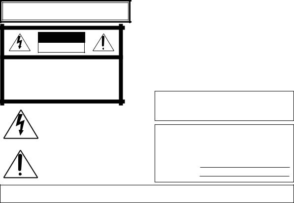
CAUTION
RISK OF ELECTRIC SHOCK
DO NOT OPEN
CAUTION:
TO REDUCE THE RISK OF ELECTRIC SHOCK, DO NOT REMOVE COVER (OR BACK), NO USER SERVICEABLE PARTS INSIDE.
REFER SERVICING TO QUALIFIED SERVICE PERSONNEL.
The lightning flash with arrowhead symbol, within an equilateral triangle, is interned to alert the user to the presence of uninsulated "dangerous voltage" within the product's enclosure that may be of sufficient magnitude to constitute a risk of electric shock to persons.
The exclamation point within an equilateral triangle is intended to alert the user to the presence of important operating and maintenance (servicing) instructions in the literature accompanying the appliance.
We declare under our sole responsibility that the product to which this declaration relates is in conformity with the standards or other normative documents following the provisions of Directives EEC/73/23 and EEC/89/336.
Noi dichiariamo sotto nostra esclusiva responsabilità che il prodotto a cui si riferisce la presente dichiarazione risulta conforme ai seguenti standard o altri documenti normativi conformi alle disposizioni delle direttive CEE/73/23 e CEE/89/336.
Wij verklaren als enige aansprakelijke, dat het product waarop deze verklaring betrekking heeft, voldoet aan de volgende normen of andere normatiefve dokumenten, overeenkomstig de bepalingen van Richtlijnen 73/23/EEC en 89/336/EEC.
Vi erklærer os eneansvarlige for, at dette produkt, som denne deklaration omhandler, er i overensstemmelse med den følgende standarder eller andre normative dokumenter i følge bestemmelserne i direktivene 73/23/EEC og 89/336/EEC.
Vi deklarerar härmed värt fulla ansvar för att den produkt till vilken denna deklaration hänvisar är i överensstämmelse med standarddokument, eller andra normativa dokument som framstölls i Direktiv 73/23/EEC och 89/336/EEC.
Ilmoitamme yksinomaisella vastuullamme, että tuote, jota tämä ilmoitus koskee, noudattaa seuraavia standardeja tai muita ohjeellisia asiakirjoja, jotka noudattavat direktiivien 73/23/EEC ia 89/336/EEC. säädöksiä.
Vi erklærer oss alene ansvarlige for at produktet som denne erklæringen gjelder for, er i overensstemmelse med følgende normer eller andre normgivende dokumenter som fælger bestemmelsene i direktiven 73/23/EEC og 89/336/EEC.
WARNING:
TO PREVENT FIRE OR ELECTRIC SHOCK HAZARD, DO NOT EXPOSE THIS APPLIANCE TO RAIN OR MOISTURE.
For U.K.
FOR YOUR SAFETY PLEASE READ THE FOLLOWING TEXT CARE- |
IMPORTANT |
|
|
FULLY. |
The wires in this mains lead are coloured in accordance with the following |
||
This appliance is supplied with a moulded three pin mains plug for your |
|||
code. |
|
||
safety and convenience. |
|
||
Green-and-yellow: |
Earth |
||
A 5 amp fuse is fitted in this plug. |
|||
Blue: |
Neutral |
||
Should the fuse need to be replaced please ensure that the replacement |
|||
Brown: |
Live |
||
fuse has a rating of 5 amp and that it is approved by ASTA or BSI to |
|||
As the colours of the wire in the mains lead of this appliance may not |
|||
BS1362. |
|||
Check for the ASTA mark Hor the BSI mark Gon the body of the fuse. |
correspond with the coloured markings identifying the terminals in your |
||
If the plug contains a removable fuse cover you must ensure that it is refit- |
plug, proceed as follows. |
|
|
ted when the fuse is replaced. |
The wire which is coloured green-and-yellow must be connected to |
||
If you lose the fuse cover the plug must not be used until a replacement |
the terminal in the plug which is marked with the letter E or by the earth |
||
cover is obtained. |
symbol Ior coloured green or green-and-yellow. |
||
A replacement fuse cover can be purchased from your local Panasonic |
The wire which is coloured blue must be connected to the terminal in |
||
Dealer. |
the plug which is marked with the letter N or coloured black. |
||
IF THE FITTED MOULDED PLUG IS UNSUITABLE FOR THE SOCKET |
The wire which is coloured brown must be connected to the terminal |
||
in the plug which is marked with the letter L or |
red. |
||
OUTLET IN YOUR HOME THEN THE FUSE SHOULD BE REMOVED |
|||
|
|
||
AND THE PLUG CUT OFF AND DISPOSED OF SAFELY. |
How to replace the fuse |
|
|
THERE IS A DANGER OF SEVERE ELECTRICAL SHOCK IF THE CUT |
|
||
Open the fuse compartment with |
|
||
OFF PLUG IS INSERTED INTO ANY 13 AMP SOCKET. |
|
||
a screwdriver and replace the fuse |
|
||
|
|
||
If a new plug is to be fitted please observe the wiring code as shown below. |
and fuse cover. |
|
|
If in any doubt please consult a qualified electrician. |
|
|
|
WARNING: This apparatus must be earthed. |
|
|
|
|
|
|
|
The serial number of this product may be found on the top of the unit.
You should note the serial number of this unit in the space provided and retain this book as a permanent record of your purchase to aid identification in the event of theft.
Model No.
Serial No.
ENGLISH
-1-
CONTENTS |
|
PREFACE ........................................................................................................................................................................ |
3 |
FEATURES ...................................................................................................................................................................... |
3 |
PRECAUTIONS ............................................................................................................................................................... |
4 |
MAJOR OPERATING CONTROLS AND THEIR FUNCTIONS ......................................................................................... |
5 |
CONNECTIONS .............................................................................................................................................................. |
8 |
FOCUS OR BACK-FOCAL ADJUSTMENT ................................................................................................................... |
13 |
INSTALLATION OF CAMERA ....................................................................................................................................... |
14 |
PREVENTION OF BLOOMING AND SMEAR ................................................................................................................ |
15 |
SPECIFICATIONS ......................................................................................................................................................... |
16 |
STANDARD ACCESSORIES .......................................................................................................................................... |
17 |
-2-

PREFACE
Panasonic’s WV-BP130 series introduces a new level of high picture quality and high resolution through the use of a 1/3-inch interline transfer CCD image sensor having 512 horizontal pixels (picture elements). This
model offers cutting-edge technology for advanced video surveillance.
FEATURES
1.The following functions are built-in.
(1)Auto Light Control (ALC)/Electronic Light Control (ELC)
(2)Back Light Compensation
(3)Line-locked Sync or automatic switching Multiplexed Vertical Drive (VD2) (only WVBP130 and WV-BP134)/Internal Sync or automatic switching VD2 (only WV-BP132)
2.Signal-to noise ratio of 46 dB
3.Minimum illumination of 0.08 lx (0.008 foot-candle) with F1.4 lenses
4.Horizontal resolution of 380 lines
5.Shooting of indoor scenes with fixed iris lens by use of Electronic Light Control (ELC) function
6.Selectable auto iris control signal for the lens from a video signal or DC control signal
-3-

PRECAUTIONS
1.Do not attempt to disassemble the camera.
To prevent electric shock, do not remove screws or covers.
There are no user serviceable parts inside. Ask a qualified service person for servicing.
2.Handle the camera with care.
Do not abuse the camera. Avoid striking, shaking, etc. The camera could be damaged by improper handling or storage.
3.Do not expose the camera to rain or moisture, or try to operate it in wet areas.
Turn the power off immediately and ask a qualified service person for servicing. Moisture can damage the camera and also create the danger of electric shock.
4.Do not use strong or abrasive detergents when cleaning the camera body.
Use a dry cloth to clean the camera when dirty.
In case the dirt is hard to remove, use a mild detergent and wipe gently.
5.Clean the CCD faceplate with care.
Do not clean the CCD with strong or abrasive detergents. Use lens tissue or a cotton tipped applicator and ethanol.
6.Never face the camera towards the sun.
Do not aim the camera at bright objects. Whether the camera is in use or not, never aim it at the sun or other extremely bright objects. Otherwise, blooming or smear may be caused.
7.Do not operate the camera beyond the specified temperature, humidity or power source ratings.
Use the camera under conditions where temperature is between −10°C - +50°C (14°F - 122°F), and
humidity is below 90%. The input power source is 220 - 240V AC, 50Hz for WV-BL130, AC 24V 50 Hz for WV-BP134, 12V DC for WV-BL132.
-4-

MAJOR OPERATING CONTROLS AND THEIR FUNCTIONS
MAJOR OPERATING CONTROLS AND THEIR FUNCTIONS
WV-BP130
ALC ELC
DC VIDEO
|
|
DC 12V IN |
|
AC 24V IN |
GND |
||
|
|
|
|
|
|
||
|
|
|
|
1 |
2 |
|
|
VIDEO OUT |
BLC |
VIDEO OUT |
BLC |
VIDEO OUT |
BLC |
||
OFF ON |
OFF ON |
OFF ON |
|||||
|
|
|
|
||||
|
ALC |
|
ALC |
|
|
ALC |
|
|
ELC |
|
ELC |
|
|
ELC |
|
WV-BP130 |
WV-BP132 |
WV-BP134 |
-5-
qLens Type and Drive Signal Selector (ALC (VIDEO/DC), ELC)
Lets you select the mode according to the lens type that is used with this camera.
ALC: Lets you select this mode when an auto iris lens (ALC lens) is used with this camera.
ELC: Select this mode when a fixed iris lens or manual iris lens is used with this camera.
If you have selected ALC select the mode according to the type of auto iris lens drive signal to be supplied to the lens from the auto iris lens connector.
VIDEO: Select this mode if you are using the auto iris lens that requires a video drive signal.
DC: Select this mode if you are using the auto iris lens that requires a DC drive signal.
wAuto Iris lens Connector
This connector is for connecting the auto iris lens by a 4-pin male connector supplied as a standard accessory (Part No. YFE4191J100).
eCamera Mounting Screw Hole
This hole is for mounting the camera onto a mounting bracket.
rBack-focal Adjusting Ring
This ring adjusts the back focal length or picture
focus. Rotate this ring clockwise for a C-mount lens or counterclockwise for a CS-mount lens.
t Lens (option)
yPower Cord (only WV-BP130)
Connect this power cord to an electrical outlet of 220 - 240V AC 50 Hz.
uDC 12 V Input Terminal (DC 12V IN (only WVBP132))
This terminal is for connecting the 12V DC power supply cord.
i24V AC Input Terminal (AC 24V IN (only WVBP134))
This terminal is for connecting the AC 24V 50 Hz power supply cord.
oVideo Output Connector (VIDEO OUT)
This connector is for connecting with the VIDEO IN connector of the monitor.
-6-

!0Back Light Compensation On/Off Selectors
(BLC ON/OFF, ALC/ELC)
Lets you select BLC ON or OFF according to the position of the object and light condition in the screen.
BLC ON: Select this mode if the background light is strong such as a spotlight. The back light compensation functions.
OFF: Normal camera picture is displayed.
1.Confirm the position of the lens type and drive signal selector.
2.If you have selected ALC (VIDEO/DC), use the upper selector (ALC) to select the mode.
If ELC is selected, select the mode by lower selector (ELC).
Caution:
Connect to 12V DC (10.5V-16V) or 24V AC (19.5V-28V) class 2 power supply only. Make sure to connect the grounding lead to the GND terminal when the power is supplied from a 24V AC power source.
-7-
CONNECTIONS
A. WV-BP130 (220 - 240V AC 50 Hz)
Connect the power cord to an electrical outlet of 220 - 240V AC 50 Hz.
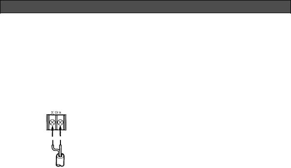
B. WV-BP132 (12V DC)
Connect the power cord to the DC 12V IN terminal on the rear panel of the WV-BP132.
@ !
12V DC
(10.5 V - 16 V)
Resistance of copper wire [at 20°C (68°F)]
Copper wire |
#24 |
#22 |
#20 |
#18 |
size (AWG) |
(0.22mm2) |
(0.33mm2) |
(0.52mm2) |
(0.83mm2) |
|
|
|
|
|
Resistance |
0.078 |
0.050 |
0.030 |
0.018 |
Ω/m |
|
|
|
|
|
|
|
|
|
Resistance |
0.026 |
0.017 |
0.010 |
0.006 |
Ω/ft |
|
|
|
|
|
|
|
|
|
•Calculation of maximum cable length between camera and power supply :
10.5V DC ≤ VA − (R x 0.42 x L) ≤ 16V DC
L : Cable length (meters)
R : Resistance of copper wire (Ω/meters) VA : DC output voltage of power supply unit
|
|
VA − 12 |
|||
L standard = |
|
|
|
|
(meters) |
|
|
||||
|
|
0.42 x R |
|||
|
|
VA − 16 |
|||
L minimum = |
|
|
|
|
(meters) |
|
|
|
|||
|
|
0.42 x R |
|||
|
VA − 10.5 |
||||
L maximum = |
|
|
|
|
(meters) |
|
|
0.42 x R |
|||
-8-
C. WV-BP134 (24V AC 50 Hz)
Connect the power cable to the AC 24V IN terminal on the rear panel of the WV-BP134.
1 2
24V AC, 50 Hz
(19.5 V - 28 V)
Recommended wire gauge sizes for 24V AC line
Copper wire |
|
#24 |
#22 |
#20 |
#18 |
|
size (AWG) |
|
(0.22mm2) |
(0.33mm2) |
(0.52mm2) |
(0.83mm2) |
|
|
|
|
|
|
|
|
Length |
|
(m) |
95 |
150 |
255 |
425 |
of Cable |
|
|
|
|
|
|
|
|
|
|
|
|
|
(Approx.) |
|
(ft) |
314 |
495 |
842 |
1 403 |
|
|
|
|
|
|
|
Video Cable
1.It is recommended to use a monitor whose resolution is at least equal to that of the camera.
2.Set the termination switch to the 75Ω position on the last monitor.
A.Use a 75Ω coaxial cable.
B.Set the termination switch to the 75Ω position on the last monitor and to the Hi-Z position on the other monitors. Do not change the positions after setting.
|
Monitor |
|
Monitor |
|
VIDEO |
|
VIDEO |
IN |
OUT 75 ¶ |
IN |
OUT 75 ¶ |
|
Hi-Z |
|
Hi-Z |
C.The maximum extensible coaxial cable length between the camera and the monitor is shown below.
-9-
Type of |
|
RG-59/U |
RG-6/U |
RG-11/U |
RG-15/U |
coaxial cable |
|
(3C-2V) |
(5C-2V) |
(7C-2V) |
(10C-2V) |
|
|
|
|
|
|
Recommended |
(m) |
250 |
500 |
600 |
800 |
maximum |
|
|
|
|
|
|
|
|
|
|
|
cable length |
(ft) |
825 |
1 650 |
1 980 |
2 640 |
|
|
|
|
|
|
3. Wiring precautions
•Do not bend the coaxial cable into a curve whose radius is smaller than 10 times the cable’s diameter.
•Never staple the cable, not even with circular staples. Impedance mismatching will occur.
•Never crush or pinch the cable.
All of the above will change the impedance of the cable and cause poor picture quality.
-10-
Installation of Auto Iris Lens Connector
Install the lens connector (YFE4191J100) when using a video drive ALC lens.
The installation should be made by qualified service personnel or system installers.
(1)Cut the iris control cable at the edge of the lens connector to remove the existing lens connector and then remove the outer cable cover as shown in the diagram below.
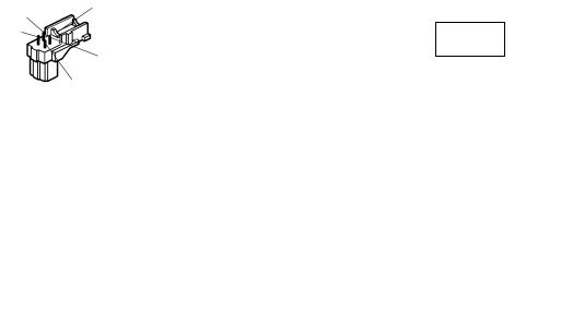
The pin assignment of the lens connector is as follows:
Pin 1: Power source; +9V DC, 50mA max.
Pin 2: Not used
Pin 3: Video signal; 0.7 V[p-p]/40 kΩ Pin 4: Shield, ground
Rib
Pin 3
Pin 1
Pin 4
Pin 2
(2)After connection, assemble the lens connector as follows.
Connector
Cover Automatic
Iris Lens
Heat
Shrinkable
Tubes
Iris Control
Cable
Connector
Note: When the iris control cable is too thick to lock the connector cover with the connector base, cut off the rib on the connector.
(Set the lens type and drive signal selector to VIDEO)
-11-
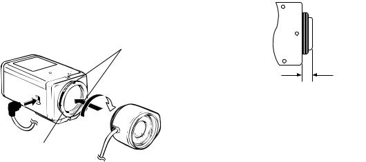
Mounting the Lens
Caution:
Before you mount the lens, loosen the two screws on the ring, and rotate this ring clockwise until it stops. If the ring is not at the end, the inner Lens or CCD image sensor may be damaged.
1.Mount the lens by turning it clockwise on the lens mount of the camera.
2.Connect the lens cable to the auto iris lens connector on the side of the camera.
Screws
Caution for Mounting the Lens
The lens mount should be a C-mount or CS-mount (1”- 32UN) and the lens weight should be less than 450g (0.99 lbs). If the lens is heavier, both the lens and camera should be secured by using the supporter.
The protrusion at the rear of the lens should be as shown below:


 1 2
1 2 


Back-focal
Adjusting Ring
C-mount: Less than 11.5mm (7/16”) CS-mount: Less than 7.2 mm (1/4”)
-12-
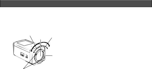
FOCUS OR BACK-FOCAL ADJUSTMENT
The following adjustment should be made by qualified service personnel or system installers.
1.Loosen the screws on the back-focal adjusting ring.
Focus adjustment for |
Focus adjustment for |
|
CS-mount lens |
||
C-mount lens |
||
|
Back-focal
Adjusting Ring
Screws
2.Turn the back-focal adjusting ring to the desired position.
Caution: When the C-mount lens is mounted, do not rotate the ring counterclockwise by force after it stops. If the ring is rotated by force, the inner lens or CCD image sensor may be damaged.
-13-
3.Tighten the screws on the back-focal adjusting ring.

INSTALLATION OF CAMERA
• Mounting from the bottom
This camera is designed to be mounted from the bottom, as shown below. The mounting hole is a standard photographic pan-head screw size (1/4” - 20).
<Mounting at top>
<Mounting at bottom>
• Mounting from the top
Remove the mount adapter from the bottom of the camera by removing the two fixing screws. Attach the mount adapter to the top as shown in the diagram, then mount the camera on the mounting bracket.
Make sure that the two original fixing screws are used when mounting the mount adapter as longer length screws may damage inner components.
Fixing Screws
Mount Adapter
-14-

PREVENTION OF BLOOMING AND SMEAR
When the camera is aimed at a bright light, such as a |
|
Smear |
spotlight, or a surface that reflects bright light, smear |
|
Bright object |
or blooming may appear. Therefore, the camera |
|
|
|
|
|
should be operated carefully in the vicinity of extremely |
|
|
bright objects to avoid smear or blooming |
|
|
|
|
|
-15-

SPECIFICATIONS
Pick-up Device: |
512 (H) x 582 (V) pixels, Interline Transfer CCD |
|
Scanning Area: |
4.8 (H) x 3.6 (V) mm (Equivalent to scanning area of 1/3” pick-up tube) |
|
Synchronization: |
Line-locked or Multiplexed Vertical Drive (VD2) for WV-BP130 and WV-BP134 |
|
|
Internal or Multiplexed Vertical Drive (VD2) for WV-BP132 |
|
Scanning System: |
2 : 1 interlace |
|
Scanning: |
625 lines / 50 fields / 25 frames |
|
Horizontal: |
15.625 kHz |
|
Vertical: |
50 Hz |
|
Video Output: |
1.0 V[p-p] CCIR composite 75 Ω / BNC connector |
|
Horizontal Resolution: |
380 lines |
|
Signal-to-Noise Ratio: |
46 dB |
|
Electronic Light Control: |
Equivalent to continuous variable shutter speed between 1/50 s |
|
|
and 1/80 000 s |
|
Minimum Illumination: |
0.08 lx (0.008 foot-candle) at F1.4 |
|
Lens Mount: |
C-mount or CS-mount selectable |
|
Ambient Operating Temperature: |
−10°C - +50°C (14°F - 122°F) |
|
Ambient Operating Humidity: |
Less than 90% |
|
Power Source and |
WV-BP130 |
220 - 240V AC 50 Hz, 3.0W |
Power Consumption: |
WV-BP132 |
12V DC 160 mA |
|
WV-BP134 |
24V AC 50Hz, 2.8W |
-16-

Dimensions (without lens): |
67 (W) x 55 (H) x 123 (D) mm |
|
|
[2-5/8” (W) x 2-3/16” (H) x 4-13/16” (D)] |
|
Weights (without lens): |
WV-BP130 |
630 g (1.39 lbs.) |
|
WV-BP132 |
410 g (0.90 lbs.) |
|
WV-BP134 |
440 g (0.97 lbs.) |
Weights and dimensions indicated are approximate.
Specifications are subject to change without notice.
STANDARD ACCESSORIES
Body Cap ............................................................................. |
1 pc. |
ALC Lens Connector (YFE4191J100) .................................. |
1 pc. |
-17-
DEUTSCHE AUSGABE
(GERMAN VERSION)
CAUTION
RISK OF ELECTRIC SHOCK
DO NOT OPEN
WARNUNG:
WEDER DECKEL NOCH RÜCKPLATTE ABNEHMEN, UM DIE GEFAHR EINES ELEKTRISCHEN SCHLAGS ZU VERMEIDEN, DAS GERÄT ENTHÄLT KEINE BAUTEILE, DIE VOM KUNDEN GEWARTET WERDEN KÖNNEN.
Das Blitzzeichen mit Pfeil im gleichseitigen Dreieck soll den Benutzer auf das Vorhandensein von nichtisolierter "gefährlicher Spannung" innerhalb des Gehäuses hinweisen, die so groß sein kann, daß sie Gefahr eines elektrischen Schlags darstellt.
Das Ausrufezeichen im gleichseitigen Dreieck soll den Benutzer auf wichtige Bedienungs und Wartungsanweisungen in den Unterlagen hinweisen, die dem Gerät beiliegen.
Wir erklären in alleiniger Verantwortung, daß das Produkt, auf das sich diese Erklärung bezieht, mit der folgenden Normen oder normativen Dokumenten übereinstimmt. Gemäß den Bestimmungen der Richtlinite 73/23/EEC und 89/336/EEC.
Die Fabriknummer dieses Gerätes ist auf dessen oberen Abdeckung angegeben.
Sie sollten die Fabriknummer dieses Gerätes in den da-für vorgesehenen Raum eintragen und diese Anleitung als Kaufsunterlage aufbewahren, um im Falle eines Diebstahls die ldentifizierung zu erleichtern.
Modellnummer
Fabriknummer
WARNUNG: UM DIE GEFAHR VON BRAND ODER STROMSCHLAG ZU VERHÜTEN, DIESES GERÄT WEDER REGEN NOCH FEUCHTIGKEIT AUSSETZEN.
-18-
INHALT |
|
VORWORT .................................................................................................................................................................... |
20 |
MERKMALE .................................................................................................................................................................. |
20 |
VORSICHTSMASSREGELN .......................................................................................................................................... |
21 |
WICHTIGE BEDIENUNGSELEMENTE UND IHRE FUNKTIONEN ................................................................................ |
22 |
ANSCHLÜSSE .............................................................................................................................................................. |
25 |
SCHARFODER RÜCKFLANSCHEINSTELLUNG ........................................................................................................ |
30 |
EINBAU DER KAMERA ................................................................................................................................................. |
31 |
VERMEIDUNG VON ÜBERSTRAHLEN UND LEUCHTFAHNEN ................................................................................... |
32 |
TECHNISCHE DATEN ................................................................................................................................................... |
33 |
NORMALZUBEHÖR ...................................................................................................................................................... |
34 |
DEUTSCH
-19-

VORWORT
Die Kameras der Serie WV-BP130 von Panasonic gewährleisten eine neue Ebene an Bildqualität und hohem Auflösungsvermögen dank der Verwendung eines 1/3-Zoll Zwischenzeilen-CCD-Bildaufnahmeele-
ments, das 512 horizontale Pixel (Bildelemente) aufweist. Sie bieten somit überlegene Technologie für fortschrittliche Bildüberwachung.
MERKMALE
1.Die folgenden Funktionen sind eingebaut:
(1)Automatische Lichtsteuerung (ALC)/Elektronische Lichtsteuerung (ELC)
(2)Gegenlichtkompensation
(3)Zeilensynchronisierung oder automatische Umschaltung zwischen Multiplex-Vertika- lantrieb (VD2) (nur WV-BP130 und WVBP134)/Interner Synchronisierung oder automatischer Umschaltung von VD2 (nur WVBP132)
2.Signal-Rauschabstand 46 dB
3.Minimale Beleuchtung 0,08 Lux mit F1,4 Objektiven
4.Horizontale Auflösung von 380 Zeilen
5.Aufnahme von Szenen in Räumen mit Festblendenobjektiven durch die Verwendung der Elektronischen Lichtsteuerungsfunktion (ELC)
6.Blendenautomatik-Steuersignal für das Objektiv wählbar aus dem Videosignal oder dem DCSteuersignal
-20-
Loading...