


Wj-Ms424
Table of contents
 Loading...
Quad Unit
WJ-MS424
Before attempting to connect or operate this product, please read these instructions completely
ENGLISH
DEUTSCH
FRANÇAIS
ESPAÑOL
The serial number of this product may be found on the
rear of the unit.
You should note the serial number of this unit in the
space provided and retain this book as a permanent
record of your purchase to aid identification in the event
of theft.
Model No.
Serial No.
THIS APPARATUS MUST BE EARTHED.
To ensure safe operation the three-pin plug supplied must be insert-
ed only into a standard three-pin power point which is effectively
earthed through the normal household wiring. Extension cords used
with the equipment must be three-core and be correctly wired to pro-
vide connection to earth. Wrongly wired extension cords are a major
cause of fatalities.
The fact that the equipment operates satisfactorily does not imply
that the power point is earthed and that the installation is completely
safe. For your safety, if in any doubt about the effective earthing of
the power point, consult a qualified electrician.
The lightning flash with arrowhead sym-
bol, within an equilateral triangle, is
interned to alert the user to the presence
of uninsulated "dangerous voltage" within
the product's enclosure that may be of
sufficient magnitude to constitute a risk of
electric shock to persons.
The exclamation point within an equilat-
eral triangle is intended to alert the user
to the presence of important operating
and maintenance (servicing) instructions
in the literature accompanying the appli-
ance.
WARNING:
TO PREVENT FIRE OR ELECTRIC SHOCK HAZARD, DO NOT EXPOSE THIS APPLIANCE TO RAIN OR MOIS
TURE.
CAUTION:
TO REDUCE THE RISK OF ELECTRIC SHOCK,
DO NOT REMOVE COVER (OR BACK), NO USER
SERVICEABLE PARTS INSIDE.
REFER SERVICING TO QUALIFIED SERVICE
PERSONNEL.
CAUTION
RISK OF ELECTRIC SHOCK
DO NOT OPEN
For Australia
FOR YOUR SAFETY PLEASE READ THE FOLLOWING TEXT CARE-
FULLY.
This appliance is supplied with a moulded three pin mains plug for your
safety and convenience.
A 13 amp fuse is fitted in this plug.
Should the fuse need to be replaced please ensure that the replacement
fuse has a rating of 13 amp and that it is approved by ASTA or BSI to
BS1362.
Check for the ASTA mark
H or the BSI mark G on the body of the
fuse.
If the plug contains a removable fuse cover you must ensure that it is
refitted when the fuse is replaced.
If you lose the fuse cover the plug must not be used until a replacement
cover is obtained.
A replacement fuse cover can be purchased from your local Panasonic
Dealer.
IF THE FITTED MOULDED PLUG IS UNSUITABLE FOR THE SOCK-
ET OUTLET IN YOUR HOME THEN THE FUSE SHOULD BE
REMOVED AND THE PLUG CUT OFF AND DISPOSED OF SAFELY.
THERE IS A DANGER OF SEVERE ELECTRICAL SHOCK IF THE
CUT OFF PLUG IS INSERTED INTO ANY 13 AMP SOCKET.
If a new plug is to be fitted please observe the wiring code as shown
below.
If in any doubt please consult a qualified electrician.
WARNING: This apparatus must be earthed.
IMPORTANT
The wires in this mains lead are coloured in accordance with the follow-
ing code.
Green-and-yellow: Earth
Blue: Neutral
Brown: Live
As the colours of the wire in the mains lead of this appliance may not
correspond with the coloured markings identifying the terminals in your
plug, proceed as follows.
The wire which is coloured green-and-yellow must be connected to
the terminal in the plug which is marked with the letter E or by the earth
symbol
I or coloured green or green-and-yellow.
The wire which is coloured blue must be connected to the terminal in
the plug which is marked with the letter N or coloured black.
The wire which is coloured brown must be connected to the terminal
in the plug which is marked with the letter L or coloured red.
How to replace the fuse
Open the fuse compartment with
a screwdriver and replace the fuse
and fuse cover.
For U.K.
ENGLISH VERSION
CAUTION:
Before attempting to connect or operate this prod-
uct, please read the label on the bottom.

-1-
CONTENTS
PREFACE .................................................................................................................................................................................. 2
FEATURES ................................................................................................................................................................................ 2
PRECAUTIONS ......................................................................................................................................................................... 2
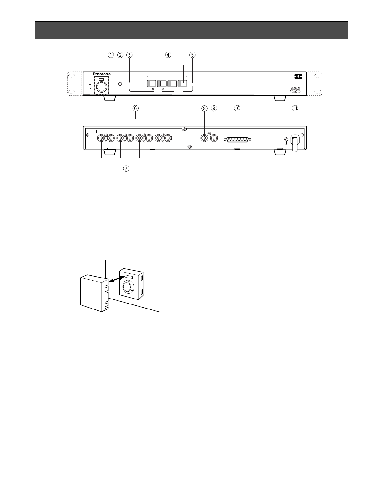
MAJOR OPERATING CONTROLS AND THEIR FUNCTIONS ................................................................................................... 3
RACK MOUNTING .................................................................................................................................................................... 5
SETTING UP THE MENUS ........................................................................................................................................................ 6
SYSTEM CONNECTIONS ....................................................................................................................................................... 12
SPECIFICATIONS ................................................................................................................................................................... 16
STANDARD ACCESSORIES ................................................................................................................................................... 16
Wij verklaren als enige aansprakelijke, dat het product waarop deze
verklaring betrekking heeft, voldoet aan de volgende normen of
andere normatiefve dokumenten, overeenkomstig de bepalingen
van Richtlijnen 73/23/EEC en 89/336/EEC.
Vi erklærer os eneansvarlige for, at dette produkt, som denne
deklaration omhandler, er i overensstemmelse med den følgende
standarder eller andre normative dokumenter i følge bestem-
melserne i direktivene 73/23/EEC og 89/336/EEC.
Vi deklarerar härmed värt fulla ansvar för att den produkt till vilken
denna deklaration hänvisar är i överensstämmelse med standard-
dokument, eller andra normativa dokument som framstölls i Direktiv
73/23/EEC och 89/336/EEC.
Ilmoitamme yksinomaisella vastuullamme, että tuote, jota tämä
ilmoitus koskee, noudattaa seuraavia standardeja tai muita ohjeel-
lisia asiakirjoja, jotka noudattavat direktiivien 73/23/EEC ia
89/336/EEC. säädöksiä.
Vi erklærer oss alene ansvarlige for at produktet som denne
erklæringen gjelder for, er i overensstemmelse med følgende
normer eller andre normgivende dokumenter som fælger bestem-
melsene i direktiven 73/23/EEC og 89/336/EEC.
We declare under our sole responsibility that the product to which
this declaration relates is in conformity with the standards or other
normative documents following the provisions of Directives
EEC/73/23 and EEC/89/336.
Nosotros declaramos bajo nuestra única responsabilidad que el
producto a que hace referencia esta declaración està conforme con
las normas u otros documentos normativos siguiendo las estipula-
ciones de la directivas CEE/73/23 y CEE/89/336.
Noi dichiariamo sotto nostra esclusiva responsabilità che il prodotto
a cui si riferisce la presente dichiarazione risulta conforme ai
seguenti standard o altri documenti normativi conformi alle dispo-
sizioni delle direttive CEE/73/23 e CEE/89/336.
Wir erklären in alleiniger Verantwortung, daß das Produkt, auf das
sich diese Erklärung bezieht, mit der folgenden Normen oder nor-
mativen Dokumenten übereinstimmt. Gemäß den Bestimmungen
der Richtlinite 73/23/EEC und 89/336/EEC.
ENGLISH

-2-
The Panasonic WJ-MS424 Quad Unit is ideal for CCTV
applications where multiple surveillance cameras are
required. Most 2 : 1 interlace cameras available today,
either colour or black and white, are compatible with the
WJ-MS424. Up to four cameras may be connected to
PREFACE
1. Compatible with Most 2 : 1 Interlace cameras
Advanced digital processing technology allows
connection of most 2 : 1 interlace cameras available
today without the requirement for synchronization of
the four video inputs.
The system may be added to existing security sys-
tems and makes possible displays in black and
white or full colour.
2. Alphanumeric Character Generator
Title insertion of up to 8 characters in each of the
four windows is possible. This promotes easy identi-
fication of the separate camera locations.
3. Alarm with Built-in Buzzer
This system can be combined with alarm sensors
and switches as well as time-lapse VTRs through
the alarm output and reset signal connectors.
Upon receiving an alarm signal, a full-sized picture
of the site is displayed. By setting the “CAM TITLE
ON” and “ALARM TITLE ON” modes from the TITLE
menu, “ALARM” and the window title will appear
intermittently in the picture.
The Automatic alarm reset time is adjustable from 1
to 30 sec.,1, 2, 3, 4, 5 min. or Off.
FEATURES
PRECAUTIONS
• Do not attempt to disassemble the unit. In order to
prevent electrical shock, do not remove screws or
covers. There are no user-serviceable parts inside.
• Do not abuse the unit. Avoid striking, shaking etc. It
could be damaged by improper handling or stor-
age.
• Do not use strong or abrasive detergents when
cleaning the unit body.
• Do not expose the unit to water or moisture, and do
not operate it in wet or humid areas.
• Do not use the unit in an extreme environment
where high temperature or high humidity exists.
• Handle the unit with care.
• Take immediate action if ever the unit does become
wet. Tune the power off and refer servicing to quali-
fied service personnel. Moisture can damage the
unit and also create a danger of electric shock.
• Use the unit under conditions where temperature is
within –10°C to +50°C (14°F to 122°F), and humidity
is below 90%. When installing the unit in the rack, it
is recommended to install the fan.
• The input power source is 220 - 240 V AC, 50 Hz.
• Refer all installation work to qualified service per-
sonnel or system installers.
4. Quad Picture Borderlines
A white borderline can be inserted in the quad pic-
tures by setting “BORDER ON” from the Setup
Menu.
5. Two kinds of Video Output Connectors
The Quad system offers two kinds of video output
connectors :
(a) VIDEO OUT : Quad or full-size single picture
can be selected with the front panel switches.
(b) VTR OUT : A quad display is always supplied,
regardless of the setting of the front panel
switches.
6. A back-up memory inside maintains preset title
character information.
7. Video Loss Checking Function
If the video signal is lost due to a disconnected
cable or other reasons, an alarm buzzer beeps and
a caution message is displayed on the monitor
screen.
the system, and if desired, the monitor can be divided
into 4 windows for simultaneous display of the four dif-
ferent images.
Simple front panel switch operation allows quick selec-
tion between quad and single camera display modes.
-3-
1. Power ON/OFF Switch (POWER)
This switch turns the power of this switch on or off. The
POWER indicator lights when the power of this unit is
on.
Switch Protector (Standard Accessory)
To prevent that the power of this unit is turned off acci-
dentally, install the supplied switch protector as shown
below.
• QUAD button
When QUAD is selected for VIDEO OUT on the
SYSTEM SETUP menu, this button works as the
QUAD button.
Pressing this button displays the quad picture on
the monitor screen.
• SEQ button
When SEQ is selected for VIDEO OUT on the SYS-
TEM SETUP menu, this button works as the SEQ
button.
Pressing this button displays the pictures on the
monitor screen in the sequential order and with the
dwell time set on the SEQ SETUP menu.
• ESC button
When the setup menu (SYSTEM SETUP, SEQ
SETUP, TITLE SETUP, TITLE SET or TITLE POSI) is
displayed on the monitor screen, this button works
as the ESC button.
Pressing this button returns the current setup menu to
the previous setup menu.
4. VIDEO SELECT (1, 2, 3, 4)/CURSOR
(4, 5)/SELECT(–, +) Buttons
These buttons select the video signal or move the
cursor on the setup menus.
• VIDEO SELECT(1, 2, 3, 4) buttons
When the setup menu is not displayed, these but-
tons work as VIDEO SELECT buttons.
Pressing one of these buttons selects a channel to
be displayed in single picture mode.
• CURSOR (4, 5)/SELECT(–, +) buttons
When the setup menu is displayed, these buttons
work as CURSOR (4, 5)/SELECT (–, +) buttons.
Pressing these buttons moves the cursor or select s
a mode or a parameter.
MAJOR OPERATING CONTROLS AND THEIR FUNCTIONS
VTR
OUT
1
VIDEO
OUT
ALARM/REMOTE
INOUT
2
VIDEO
INOUT
3
INOUT
4
INOUT
SIGNAL GND
ON
POWER
ALARM
MENU
ESC
ALARM RESET
QUAD/SEQ
OFF
POWER
PROTECTION
1 2 3 4
VIDEO SELECT
CURSOR SELECT
–
+
Quad System WJ-MS
SWITCH
PROTECTOR
2. Alarm LED (ALARM)
This LED flashes while the alarm signal is received.
It changes to steady light when the alarm is reset
automatically.
To turn the flashing LED off, press the ALARM
RESET/QUAD/SEQ button.
3. Alarm Reset/Quad/Sequence/Escape Button
(ALARM RESET/QUAD/SEQ/ESC)
This button has different functions in different
modes, as described below.
• ALARM RESET button
When an alarm signal is received, this button works
as the ALARM RESET button.
Pressing this button in an alarm situation cancels
the alarm mode with the following results:
1. The alarm LED stops flashing.
2. The alarm output is stopped.
3. The alarm buzzer stops beeping.
4. The video loss caution message on the monitor
screen disappears and the screen returns to
the camera picture.

-4-
4 button: This button moves the cursor to the left or
selects an item on the setup menus.
5 button: This button moves the cursor to the right
or selects an item on the setup menus.
– button: This button selects a character or a para-
meter on the setup menus.
+ button: This button selects a character or a para-
meter on the setup menus.
5. Menu Button (MENU)
Pressing this button for approx. 2 seconds displays
the setup menus. Pressing it again for approx. 1
second cancels the display of the setup menus.
6. Video input Connector (VIDEO IN 1, 2, 3, 4)
These connectors receive a composite video signal.
They are automatically terminated.
Notes:
• The input signals must meet the CCIR B/W
video signal standard, if the video inputs of this
unit are to be synchronized.
• If the input signals have a high jitter content, as
in the case of a VTR playback picture, it may
not be possible to synchronize this unit.
13
25
12
24
11
23
10
22
9
21
8
20
7
19
6
18
5
17
4
16
3
15
2
14
1
Not Used
Not Used
ALARM OUT
Not Used
ALARM RESET OUT
ALARM RECOVER IN QUAD/SEQ
Menu
Selector
REMOTE/ALARM 4
REMOTE/ALARM 3
REMOTE/ALARM 2
REMOTE/ALARM 1
GND
Pin-14 to 25 are connected to Ground
7. Video Output Connectors
(VIDEO OUT 1, 2, 3, 4)
The video input signals connected to the VIDEO IN
connector are looped through to these connectors.
Connectors a coaxial cable to these connectors
cancels the termination.
8. VTR Output Connector (VTR OUT)
The video signal for the quad picture mode is
always provided at this connector. By connecting it
to the VIDEO IN connector of the time lapse VTR,
you can record the quad picture.
9. Video Output Connector (VIDEO OUT)
The video signal selected by the QUAD/SEQ button
(quad picture) or the VIDEO SELECT button (single
picture) is output from this connector.
10. Alarm/Remote Control Connector
(ALARM/REMOTE)
This connector accepts the alarm signal from asso-
ciated alarm sensor units and the remote control
signal from the external equipment.
Caution: The input voltage should be DC 24V or
less for ALARM IN.
11. Power Cord
Loading...