


Operating Instructions
With Installation Manual (for qualified service personnel)
Electronic Board
(Interactive Panaboard)
Model No. UB-8325
Panaboard
Stand is optional.
•To assemble this unit, please refer to the Installation manual on page 83 through 99.
•Before operating this unit, please read these instructions completely and keep them carefully for future reference.
•Because of the nature of the print film, all the printed text will remain on the film.
•This unit is designed for installation by a qualified servicing dealer.
Installation performed by non-authorized individuals could cause safety-related problems with the operation of this equipment.
For U.S.A. only:
• To locate the closest authorized dealer in your area, please call 1-800-449-8989.

Thank you for purchasing the Panasonic Electronic Board.
For optimum performance and safety, please read these instructions carefully.
Accessories
|
Q’ty |
Q’ty |
• Thermal transfer film . . . . . . . . . . . . . . 1 |
• Batteries (LR03 “AAA”) . . . . . . . . . . . . . 6 |
|
• Markers (Black, Red, Blue-big) |
. . . . . . 1 each |
• Power cord . . . . . . . . . . . . . . . . . . . 1 |
• Eraser . . . . . . . . . . . . . . . . . . . . . . 1 |
• USB cable [5 m (16’ 5 3/8”)] . . . . . . . . . . . 1 |
|
• Pen holder . . . . . . . . . . . . . . . . . . . . 2 |
• A4 (Letter*1) size copy paper . . . . . . . . . 20 |
|
• Markers for interactive |
|
• Software CD-ROM . . . . . . . . . . . . . . . 1 |
(Black, Red, Blue, Green-small) |
. . . . . 1 each |
• Operating Instructions . . . . . . . . . . . . . . 1 |
• Electronic Eraser . . . . . . . . . . . . . . . . 1 |
• Wall-mounting template . . . . . . . . . . . . . 1 |
|
• Eraser cloth (for Electronic Eraser) . . . . . . . 2 |
• Warranty card*2 . . . . . . . . . . . . . . . . . 1 |
|
*1 Letter size is for U.S.A. and Canada models. *2 for U.S.A. model only.
*The markers (big) and the eraser are used for other than the interactive function.
*The markers for interactive (small) are used while inserted in the pen holder.
In this manual, the pen holder with a marker for interactive (small) is called the Electronic Pen. The Electronic Pen and the Electronic Eraser are used with the interactive function.
*The stand and wall-mounting kit are optional. By way of example, this manual describes an Electronic Board which is used with the stand.
Things you should keep a record of
Attach your sales receipt here
For your future reference
Date of purchase: _________________________ |
Serial number: ____________________________ |
Dealer’s name and address: ______________________________________________________________
Tel:
Warning about saving data
When the system storage device or any of its optional storage device is adversely effected by operational errors, static electricity, electrical noise, vibration, dust or when the power has been cut off due to malfunction, repair or inadvertently, the memory contents may be lost or changed. Before operating the system, make a point of reading the precautionary notes in the Operating Instructions and the help information, and observe them during operation.
Please observe carefully the following precaution:
•Make absolutely sure that all important data is saved by back-up or the original is saved.
The manufacturer hereby declares that it cannot be held accountable for any loss or change in any data stored on floppy disks, hard disks, optical disks, or other memory devices.
2
Federal Communications Commission Requirements
Note: This equipment has been tested and found to comply with the limits for a Class A digital device, pursuant to part 15 of the FCC Rules. These limits are designed to provide reasonable protection against harmful interference when the equipment is operated in a commercial environment. This equipment generates, uses, and can radiate radio frequency energy and, if not installed and used in accordance with the instruction manual, may cause harmful interference to radio communications. Operation of this equipment in a residential area is likely to cause harmful interference in which case the user will be required to correct the interference at his own expense.
FCC Warning: To assure continued FCC compliance, the user must use only the provided power supply cord. Also, any unauthorized changes or modifications to this equipment would void the user’s authority to operate this device.
•Microsoft, Windows, PowerPoint and CalliGrapher are either registered trademarks or trademarks of Microsoft Corporation in the United States and/or other countries.
•IBM is a trademark of International Business Machines Corporation in the United States, other countries, or both.
•Pentium is a trademark or registered trademark of Intel Corporation or its subsidiaries in the United States and other countries.
•Adobe, Acrobat, Acrobat Reader and Reader are either registered trademarks or trademarks of Adobe Systems Incorporated in the United States and/or other countries.
•SANFORD and EXPO are registered ® U.S. trademarks of SANFORD or its Affiliates.
•All trademarks referred to in this manual are property of their respective companies.
The information given in this Operating Instructions is subject to change without notice.
3
Features
The UB-8325 is equipped with two interactive functions; Projector mode and Whiteboard mode, in addition to a regular electronic board that utilizes plain paper. It is possible to use this unit as follows.
■Electronic Board Functions
• Allows copying up to 9 copies per screen
• Allows printing in 2 level contrast (Normal / Dark)
• Allows printing of 2-screens at the time by compressing them into a single sheet of paper
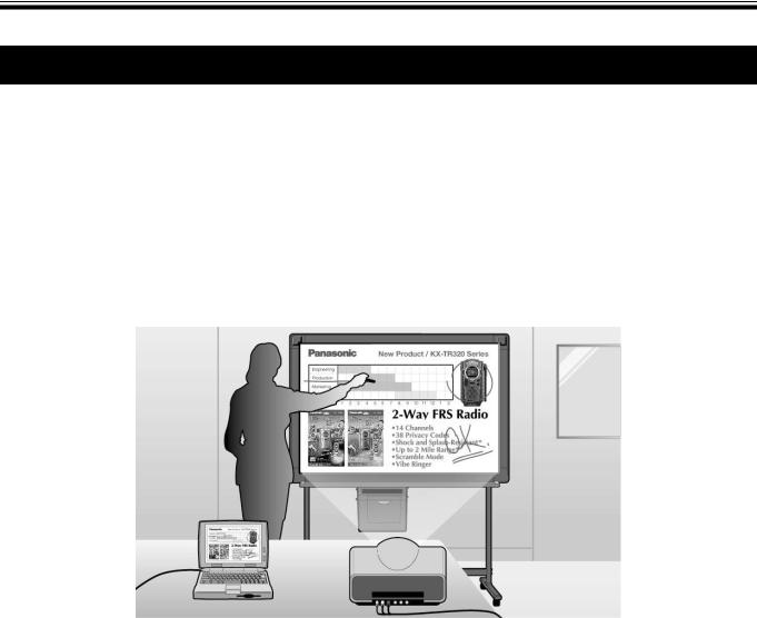
■Projector Mode (Interactive Function)
Connect the Interactive Panaboard to a computer that is connected to a projector and use the projector to project the image onto the Interactive Panaboard.
This is called the Projector mode.
In this mode, the following operations are possible:
•Operating the computer using the Electronic Pen with its cap on as a mouse
•Drawing handwritten lines or erasing it using the Electronic Pen or Electronic Eraser with its cap on in the projected image
•Saving the projected image to an image file and printing the projected image
•Recording the operations of drawing and erasing handwritten lines, playing back and editing the recorded operations later
In Projector mode, the projected computer image on the screen of the Interactive Panaboard can be operated by using the Electronic Pen as a mouse. You can execute the application and electronically write or erase notes. The electronically handwritten or partially erased computer image can be stored into an image file. This will help make your presentation more impressive to the attendants.
4
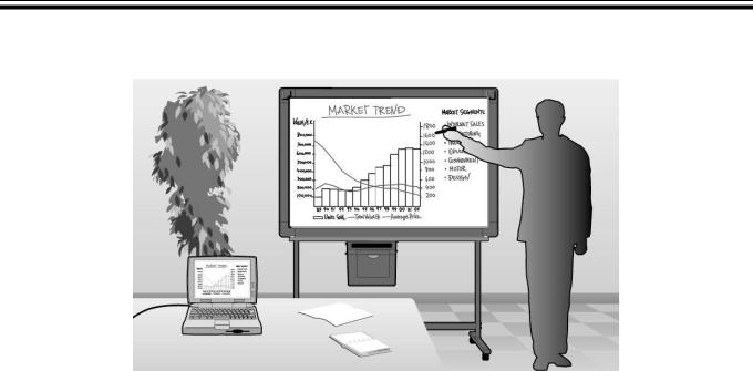
■Whiteboard Mode (Interactive Function)
By connecting the Interactive Panaboard to a computer, the information written on the Interactive Panaboard is displayed on the computer in real-time.
This is called the Whiteboard mode.
In this mode, the following operations are possible:
•The information written on the Interactive Panaboard using the Electronic Pen with its cap off will be displayed on the computer screen at the same time.
•The information erased using the Electronic Eraser will be erased in the computer as well.
•You can save drawings and notes into a file which can later be printed.
•Allows the user to record the information being written or erased in a file that can be played back as a movie and it can be edited if needed.
■Computer Interfacing
Panasonic Document Management System (hereafter referred to as Panasonic-DMS) has the following functions. About the Panasonic-DMS, refer to the Document Management System operating instructions in the CD-ROM.
•Panasonic-DMS uses the TWAIN driver to scan monochrome images drawn on the UB-8325.
•Panasonic-DMS has a capability of managing documents (image files).
•The printer driver allows the printer of the UB-8325 to print documents from a computer.
5

Table of Contents
Page
Before You Start
For Your Safety. . . . . . . . . . . . . . . . . . . . . . . . . . . . . . . . . . . . . . . . . 8
• For Users . . . . . . . . . . . . . . . . . . . . . . . . . . . . . . . . . . . . . . . . . . . . . . . . . . . . . . 8
• For users in the United Kingdom only . . . . . . . . . . . . . . . . . . . . . . . . . . . . . . . 10
Precautions. . . . . . . . . . . . . . . . . . . . . . . . . . . . . . . . . . . . . . . . . . . 11
• CD-ROM . . . . . . . . . . . . . . . . . . . . . . . . . . . . . . . . . . . . . . . . . . . . . . . . . . . . . 14
Part Names and Functions . . . . . . . . . . . . . . . . . . . . . . . . . . . . . . 15
• Control Panel . . . . . . . . . . . . . . . . . . . . . . . . . . . . . . . . . . . . . . . . . . . . . . . . . . 16
• Electronic Pen and Eraser . . . . . . . . . . . . . . . . . . . . . . . . . . . . . . . . . . . . . . . . 17
Using
Installing the Thermal Transfer Film. . . . . . . . . . . . . . . . . . . . . . . 18 Loading Copy Paper. . . . . . . . . . . . . . . . . . . . . . . . . . . . . . . . . . . . 19
Making Copies . . . . . . . . . . . . . . . . . . . . . . . . . . . . . . . . . . . . . . . . 21
• Copy Types and Procedures . . . . . . . . . . . . . . . . . . . . . . . . . . . . . . . . . . . . . . 21
Replacing the Thermal Transfer Film . . . . . . . . . . . . . . . . . . . . . . 22 Paper Jams . . . . . . . . . . . . . . . . . . . . . . . . . . . . . . . . . . . . . . . . . . . 23
Setting the Electronic Pen and Eraser . . . . . . . . . . . . . . . . . . . . . 25
• Setting the Electronic Pen . . . . . . . . . . . . . . . . . . . . . . . . . . . . . . . . . . . . . . . . 25
• Setting the Electronic Eraser . . . . . . . . . . . . . . . . . . . . . . . . . . . . . . . . . . . . . . 26
• Replacing the Eraser Cloth . . . . . . . . . . . . . . . . . . . . . . . . . . . . . . . . . . . . . . . 26
Installing Drivers and Software. . . . . . . . . . . . . . . . . . . . . . . . . . . 27
• System Requirements . . . . . . . . . . . . . . . . . . . . . . . . . . . . . . . . . . . . . . . . . . . 27
• Contents of CD-ROM . . . . . . . . . . . . . . . . . . . . . . . . . . . . . . . . . . . . . . . . . . . . 27
• Installing Drivers / Interactive Panaboard Software . . . . . . . . . . . . . . . . . . . . . 28
• Installing the Panasonic-DMS Software. . . . . . . . . . . . . . . . . . . . . . . . . . . . . . 30
• Removing Drivers / Interactive Panaboard Software . . . . . . . . . . . . . . . . . . . . 31
• Removing the Panasonic-DMS Software. . . . . . . . . . . . . . . . . . . . . . . . . . . . . 31
Using the Panaboard in Projector Mode . . . . . . . . . . . . . . . . . . . 32
• Precautions When Using a Projector . . . . . . . . . . . . . . . . . . . . . . . . . . . . . . . . 32
• Starting the Interactive Panaboard Software . . . . . . . . . . . . . . . . . . . . . . . . . . 33
• Pop-up Menu Configuration . . . . . . . . . . . . . . . . . . . . . . . . . . . . . . . . . . . . . . . 34
• Basic Operation in Projector Mode . . . . . . . . . . . . . . . . . . . . . . . . . . . . . . . . . 37
• Using the Desktop Drawing Tool . . . . . . . . . . . . . . . . . . . . . . . . . . . . . . . . . . . 40
Using the Panaboard in Whiteboard Mode . . . . . . . . . . . . . . . . . 49
• Starting the Interactive Panaboard Software . . . . . . . . . . . . . . . . . . . . . . . . . . 49
• Pop-up Menu Configuration . . . . . . . . . . . . . . . . . . . . . . . . . . . . . . . . . . . . . . . 49
• Basic Operation in Whiteboard Mode . . . . . . . . . . . . . . . . . . . . . . . . . . . . . . . 50
Using the View Window or Whiteboard Window . . . . . . . . . . . . . 53
• About View Window / Whiteboard Window . . . . . . . . . . . . . . . . . . . . . . . . . . . 53
• Managing IPB Documents . . . . . . . . . . . . . . . . . . . . . . . . . . . . . . . . . . . . . . . . 57
6 

Using the Panasonic-DMS. . . . . . . . . . . . . . . . . . . . . . . . . . . . . . . 72
• Scanning . . . . . . . . . . . . . . . . . . . . . . . . . . . . . . . . . . . . . . . . . . . . . . . . . . . . . 72
• Panaboard Operation Panel. . . . . . . . . . . . . . . . . . . . . . . . . . . . . . . . . . . . . . . 73
• Printing . . . . . . . . . . . . . . . . . . . . . . . . . . . . . . . . . . . . . . . . . . . . . . . . . . . . . . . 74
Help
Daily Care and Maintenance . . . . . . . . . . . . . . . . . . . . . . . . . . . . . 75
• Cleaning the Screen and the Unit . . . . . . . . . . . . . . . . . . . . . . . . . . . . . . . . . . 75
• Caring for the Eraser . . . . . . . . . . . . . . . . . . . . . . . . . . . . . . . . . . . . . . . . . . . . 75
• Cleaning the Printer Head, Platen Roller and Pick-up Roller. . . . . . . . . . . . . . 75
• Replacing the Batteries in the Electronic Pen and the Electronic Eraser. . . . . 77
• Replacing the Cloth of the Electronic Eraser . . . . . . . . . . . . . . . . . . . . . . . . . . 77
Troubleshooting . . . . . . . . . . . . . . . . . . . . . . . . . . . . . . . . . . . . . . . 78
• Meanings of Error Codes . . . . . . . . . . . . . . . . . . . . . . . . . . . . . . . . . . . . . . . . . 80
Specifications . . . . . . . . . . . . . . . . . . . . . . . . . . . . . . . . . . . . . . . . . 81
• Optional and Separately Available Items . . . . . . . . . . . . . . . . . . . . . . . . . . . . . 82
Installation
Installation Manual . . . . . . . . . . . . . . . . . . . . . . . . . . . . . . . . . . . . . 83
Start You Before
Using
Help
Installation
7
For Your Safety
For Your Safety
To prevent severe injury and loss of life, read this section carefully before using the unit to ensure proper and safe operation of your unit.
CLASS 1 LED PRODUCT
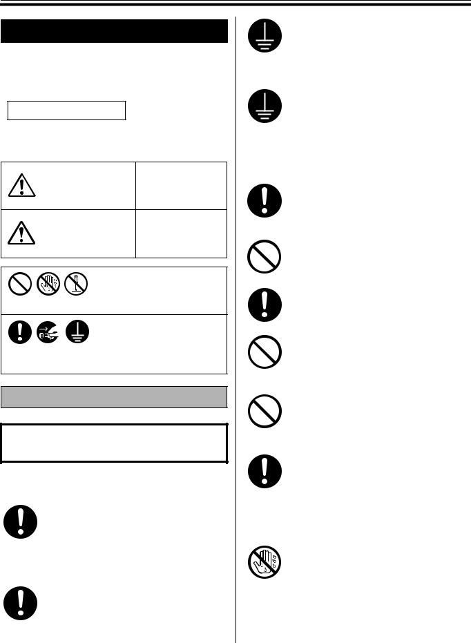
The following graphic symbols are used in this Operating Instructions manual.
Denotes a potential
hazard that could WARNING result in serious
injury or death.
Denotes hazards
that could result in CAUTION minor injury or
damage to the unit.
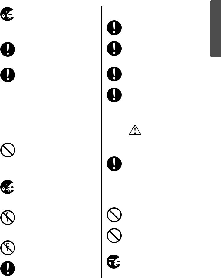
These symbols are used to alert operators to a specific operating procedure that must not be performed.
These symbols are used to alert operators to a specific operating procedure that must be emphasized in order to operate the unit safely.
For Users
 WARNING
Power and Ground Connection
The power source voltage of this unit is listed on the nameplate. Only plug the unit into an AC outlet with the proper voltage.
If you use a cord with an unspecified current rating, the unit or plug may emit smoke or become hot to the touch.
When you operate this product, the power outlet should be near the product and easily accessible.
8
To ensure safe operation the power cord supplied must be inserted into a standard three-prong AC outlet which is effectively grounded (earthed) through the normal wiring.
The fact that the equipment operates satisfactorily does not imply that the power point is grounded (earthed) and that the installation is completely safe. For your safety, if in any doubt about the effective grounding (earthing) of the power point, consult a qualified electrician.
If the plug cannot be inserted into the AC outlet, contact a licensed electrician to replace the AC outlet with a properly grounded (earthed) one.
Do not defeat the purpose of the grounding (earthing) plug (ex. do not use a conversion plug).
Plug the power cord firmly into an AC outlet. Otherwise, it can cause fire or electric shock.
Do not pull, bend, rest objects on, or chafe the power cord and plug. Damage to the power cord or plug can cause fire or electric shock.
Do not attempt to repair the power cord or plug. If the power cord or plug is damaged or frayed, contact an authorized service representative for a replacement.
Ensure that the plug connection is free of dust. In a damp environment, a contaminated connector can draw a significant amount of current that can generate heat and eventually cause fire if left unattended over an extended period of time.
Never touch the plug with wet hands. Danger of electric shock exists.
|
|
|
For Your Safety |
|
|
|
|
|
|
|
|
|
|
|
|
|
Stop operation immediately if your unit emits |
Battery |
|
|
|
smoke, excessive heat, abnormal smell or |
||
|
|
|
||
|
|
unusual noise. These conditions can cause |
Be sure to use the specified type of batteries |
|
|
|
fire or electric shock. Immediately turn the |
||
|
|
unit off and unplug the power cord, and |
only. Using incorrect type of batteries can |
|
|
|
contact your dealer for service. |
burn or leak. |
|
|
|
When disconnecting the unit, grasp the plug |
Ensure that batteries are installed with |
|
|
|
instead of the cord. Pulling on a cord forcibly |
correct polarity. Incorrectly installed batteries |
|
|
|
can damage it and cause fire or electric |
can burst or leak, resulting in spillage or |
|
|
|
shock. |
injuries. |
|
|
|
The unit should be used only with the power |
Be sure to take out batteries worn away from |
|
|
|
cord that is supplied by the manufacturer. |
the unit. The battery worn away can leak. |
|
|
|
•(220–240 V equipment) |
|
|
|
|
A certified power supply cord has to be |
|
|
|
|
used with this equipment. The relevant |
Be sure that a battery should not be |
|
|
|
national installation and/or equipment |
charged, shorted, heated, broken or thrown |
|
|
|
regulations shall be considered. A certified |
into fire. Using wrong can leak generate |
|
|
|
power supply cord is not lighter than |
heat or burst. |
|
|
|
ordinary polyvinyl chloride flexible cord |
|
|
|
|
according to IEC 60227 (designation |
|
|
|
|
H05VV-F 3G 1.0 mm2). |
|
|
Installation and Relocation |
CAUTION |
|||
|
|
To prevent fire or shock hazard, do not |
Power |
|
|
|
expose this unit to rain or any type of |
|
|
|
|
moisture. |
When the unit is not used over an extended |
|
|
|
|
||
|
|
|
period of time, switch it Off and unplug it. If |
|
Operating Safeguards |
an unused unit is left connected to a power |
|||
source for a long period, degraded insulation |
||||
|
|
|
||
|
|
If metal fragments or water gets into the unit, |
may cause electric shock, current leakage or |
|
|
|
fire. |
||
|
|
turn the unit off and unplug the unit |
|
|
|
|
immediately. Contact your dealer for service. |
|
|
|
|
Operating the contaminated unit can cause |
Installation and Relocation |
|
|
|
fire or electric shock. |
|
|
|
|
Never open or remove unit covers that are |
Do not position the unit in a location where it |
|
|
|
is unstable. |
||
|
|
screwed with screws unless specifically |
||
|
|
|
||
|
|
instructed in the “Operating Instructions”. A |
|
|
|
|
|
||
|
|
high-voltage component can cause electric |
Do not place the unit in a hot humid or dusty |
|
|
|
shock. |
||
|
|
|
environment. |
|
|
|
Do not alter the unit or modify any parts. |
Prolonged exposure to these adverse |
|
|
|
conditions may cause fire or electric shock. |
||
|
|
Alteration or modification can cause fire or |
||
|
|
|
||
|
|
electric shock. |
When moving the unit, be sure to unplug the |
|
|
|
|||
|
|
|
||
|
|
Keep the marker’s cap or battery out of |
power cord from the AC outlet. If the unit is |
|
|
|
moved with the power cord attached, it can |
||
|
|
reach of children to prevent swallowing. |
||
|
|
cause damage to the cord which could result |
||
|
|
|
||
|
|
|
in fire or electric shock. |
|
9
Start You Before

For Your Safety
Do not install the unit except by a qualified service personnel.
After installing or moving the electronic board, lock the casters and set the fallprevention extension legs.
Locking the casters (Push this side)
Push to lock |
Operating Safeguards
If the unit is fallen down or damaged, turn the unit off and unplug the power cord. Otherwise, it may cause fire or electric shock.
Do not put drinks, other liquids or heavy items on the tray or screen. Accidental spillage of liquid into the unit may cause severe damage. If this occurs, turn the unit off, unplug the power cord and contact your dealer for service.
Do not lean against the screen or on the cover (lower), even if the electronic board is mounted on the wall.
Battery
When the unit is not used over an extended period of time, take the batteries out of the unit. Otherwise, the batteries may leak. Do not use the leaked batteries.
10
For users in the United
Kingdom only
Safety Information
This appliance is supplied with a moulded three pin mains plug for your safety and convenience.
A 5 amp. fuse is fitted in this plug. Should the fuse need to be replaced please ensure that the replacement fuse has a rating of 5 amps. and that it is approved by ASTA or BSI to BS1362. Check for the ASTA mark  or the BSI mark
  on the body of the fuse. If the plug contains a removable fuse cover you must ensure that it is refitted when the fuse is replaced. If you lose the fuse cover the plug must not be used until a replacement cover is obtained. A replacement fuse cover can be purchased from your local Panasonic Dealer.
If the fitted moulded plug is unsuitable for the socket outlet in your home then the fuse should be removed and the plug cut off and disposed of safely.
There is a danger of severe electrical shock if the cut off plug is inserted into any 13 amp. socket.
If a new plug is to be fitted please observe the wiring code as shown below. If in any doubt please consult a qualified electrician.
WARNING: This appliance must be earthed. IMPORTANT: The wires in this mains lead are coloured in accordance with the following code.
Green-and-Yellow: Earth
Blue: Neutral Brown: Live
As the colours of the wire in the mains lead of this appliance may not correspond with the coloured markings identifying the terminals in your plug, proceed as follows.
The wire which is coloured Green-and-Yellow must be connected to the terminal in the plug which is marked with the letter E or by the Earth symbol  or coloured Green or Green-and-Yellow.
The wire which is coloured Blue must be connected to the terminal in the plug which is marked with the letter N or coloured Black.
The wire which is coloured Brown must be connected to the terminal in the plug which is marked with the letter L or coloured Red.
How to replace the fuse:
Open the fuse compartment with a screwdriver and replace the fuse.
Precautions
Precautions
Installation • Do not install the unit where it may be exposed to direct sunlight, near heating equipment, or near air-conditioning vents as this may cause stretching and/or discoloration of the screen.
•Do not install the unit in strong sunlight or strong lighting. Proper copying may become impossible.
•Do not install the unit in locations where the temperature may change suddenly as this may disable the unit’s ability to make copies.
Screen Film |
• Make thick and dark lines inside the copying area. |
|
|
25 mm (1" ) |
|
|
Note that any writing inside the shaded area (on |
|
|
|
|
|
right) cannot be copied. |
|
|
|
|
|
• Do not allow writing to remain on the screen for an |
35 mm |
Copying area |
35 mm |
|
|
extended period of time as it will become harder to |
||||
|
(1 |
3/8" ) |
|
(1 3/8" ) |
|
|
erase. |
|
|||
|
|
|
|
|
|
|
• Do not erase with an overly dirty eraser (see page |
|
|
|
|
|
75). |
|
|
25 mm (1" ) |
|
•Periodically wipe the screen film gently with a
water-dampened cloth that has been thoroughly wrung. (See page 75.)
•Use a commercially available white board cleaner for hard-to-erase stains. (SANFORD® EXPO® white board cleaner etc.)
•Do not touch the screen, write with markers, or erase while the screen is moving as this may result in damage to the unit.
•Do not attach chart paper to the screen film for copying as this may result in damage to the unit.
Markers, |
• Use only the included or designated markers, erasers and thermal transfer film. (See page |
Erasers and |
82.) |
Thermal |
Use of accessories other than those included or designated (such as oil-based |
Transfer Film |
markers) may damage the screen or result in hard-to-erase markings. |
•Copy quality increases with the thickness of the drawn line. To ensure quality copies, please use the markers (big).
•The markers for interactive (small) draw thin lines. The quality of the copies may be reduced when these markers are used.
•Do not store the thermal transfer film in a location subject to extreme changes in temperature (such as near air conditioning or heating equipment) as this may cause condensation on the thermal transfer film and result in poor print quality and/or paper jams.
•Store markers horizontally as vertical storage may stop the ink from coming out.
•The length of one roll of designated thermal transfer film (Replacement film: UG-6001) is approximately 50 meters (164 ft.). One roll of thermal transfer film can make approximately 150 sheets of copies.
Note that the total number of copies may differ depending on the operating conditions. Also note that the length of the thermal transfer film supplied with the unit is shorter than the replacement film roll and is only approximately 10 meters (32.8 ft.).
Power Cord |
• When moving the unit, disconnect the power cord from the electrical power socket and from |
and USB |
the printer’s power connector, and disconnect the USB cable from the printer’s USB |
Cable |
connector and a computer. Then coil them for transportation as stepping on the power cord |
|
and USB cable or having them catch on something during movement may result in damage |
|
to the cord and cable. |
•If you connect the electronic board to a USB hub, it is not guaranteed to work.
•Do not connect two or more Panasonic electronic boards to a computer. It may cause the computer operation to become unstable.
Start You Before
11

Precautions
Replacing |
• Dispose of the used thermal transfer film in a trash receptacle for burnable trash. |
the Thermal |
• A negative of the copied image will remain on the thermal transfer film. (To protect the |
Transfer Film |
security of your information, we recommend cutting up the used thermal transfer film with |
|
scissors or shredder before disposing of it.) |
|
|
Electronic |
|
Pen and |
|
Electronic |
|
Eraser |
|
Transmitter
•Do not cover the transmitter with your hand while using an interactive function as this may cause the position of the Electronic Pen or the Electronic Eraser not to be normally detected.
NG |
OK |
•Press down firmly with the point of the Electronic Pen or the eraser cloth of the Electronic Eraser on the screen film until you hear a buzzing sound, and then move it slowly. However, do not press down the point of the Electronic Pen too much strongly as this may make a dent in the screen back panel.
•Do not use two or more the Electronic Pens or the Electronic Eraser at the same time as this may cause the position of the Electronic Pen or the Electronic Eraser not to be normally detected.
•For precise positioning, keep the Electronic Pen and Electronic Eraser perpendicularly to the screen during use.
•Since ultrasonic is used to detect the position of the Electronic Pen and Electronic Eraser when they are being used, you may hear a buzzing sound, but this is not harmful to the human body or peripheral hardware. It will also not result in an electric shock.
12
|
Precautions |
|
|
|
|
|
|
Battery |
If batteries are used improperly, batteries may leak, causing corrosion of the unit, or they may |
|
burst. To prevent this, always follow the precautions given below. |
|
• Always remove batteries from the Electronic Pen and Electronic Eraser if they are not to be |
|
used for an extended period of time. |
|
• Use the same type of batteries. Do not mix different types. |
|
• Do not mix old and new batteries. |
|
• Always insert batteries with their polarity properly oriented as indicated on the Electronic |
|
Pen or Electronic Eraser. |
|
• If the Electronic Pen or Electronic Eraser ceases to function because batteries have run out, |
|
remove them immediately and dispose of them according to local regulations. |
|
Leaving drained batteries in the Electronic Pen or Electronic Eraser may result in leakage. |
|
• Do not disassemble batteries or place them in a fire. |
|
• Do not short batteries. |
|
• Alkaline batteries cannot be recharged. Never attempt to recharge alkaline batteries. |
|
For Brasil |
|
Após o uso as pilhas / baterias contidas neste produto |
|
poderão ser dispostas em lixo doméstico. |
For Taiwan ( )
Projector |
• Light from the projector may enter the eye when using a projector to project images for the |
|
purpose of making presentations and so on. Be very careful as direct projector light may |
|
hurt the eyes. |
Start You Before
13
Precautions
CD-ROM
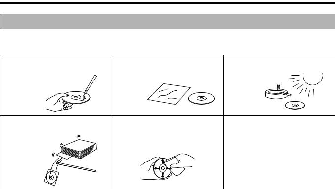
To prevent the CD-ROMs from accidental damages:
Do not touch or write on the surface |
Do not leave the disc out of the |
Do not leave the disc in direct |
of the disc. |
protective case. |
sunlight or near heat sources. |
|
|
|
|
|
|
|
Do not place heavy objects on the |
To clean the disc, hold the disc by |
|
||||
disc case or drop the case. |
its edges and wipe it from the |
|
||||
|
|
|
center to the edges with a dry, soft |
|
||
|
|
|
|
|||
|
|
|
cloth. |
|
||
|
|
|
|
|
|
|
14

Part Names and Functions
Part Names and Functions
Electronic Pen /
Electronic Eraser
Position Receiver
Printer
Output Port
This port holds up to 10 sheets of output paper.
Printer Open Lever
Push down this lever to open the printer door.
USB Connector
(See page 27.)
Scanner

 Electronic Pen /
Electronic Eraser
Position Receiver
Screen
Tray
Control Panel
(See page 16 for
details.)
Power Switch
Paper Cover
Open this cover to load copy paper.
ON
OFF

 Cord Holder
Power Cord
AC Inlet
Printer Door
Open this door to load a thermal transfer film or to remove jammed paper.
(See pages 18, 22, 23.)
Start You Before
15

Part Names and Functions
Control Panel
l |
Advance Key |
|
Contrast/Remaining Film |
||
Copy Key |
||
Indicator |
|
|
|
|
|
|
|
|
|
|
|
|
|
|
|
|
|
|
|
|
|
|
|
|
|
|
|
|
|
|
|
|
|
|
|
|
|
|
|
|
|
|
|
|
|
|
|
|
|
|
|
|
|
|
|
|
|
|
|
|
|
|
|
|
|
|
|
|
|
|
|
|
|
|
|
|
|
|
|
|
|
|
|
|
|
|
|
|
|
|
|
Contrast Key |
|
|
|
|
|
|
|
|
|
|
|
|
|
Multi-Copy/Stop Key |
||
|
|
|
|
|
|
|
|
|
|
|
|
|
|||||
|
2-Screen Copy Key |
|
|
|
|
|
|
|
|
Multi-Copy/Error Indicator |
|||||||
|
|
|
|
|
|
|
|
|
|||||||||
|
|
|
|
|
|
|
|
|
|
|
|
|
|
|
|
|
|
Panel |
Name |
|
|
|
|
|
Description |
||||||||||
|
|
|
This lamp indicator notifies the user when the time to replace the thermal transfer |
||||||||||||||
|
|
|
film is approaching (estimated) and of the printing contrast used during copying. |
||||||||||||||
|
|
|
Indicator off: |
Normal printing contrast |
|||||||||||||
|
Contrast/ |
Indicator on: |
Darker than normal printing contrast |
||||||||||||||
|
Indicator flashing*: |
Almost time to replace the thermal transfer film |
|||||||||||||||
|
Remaining |
|
|
|
|
(Note that only about 15 more sheets may be |
|||||||||||
|
Film |
|
|
|
|
copied when this indicator starts flashing.) |
|||||||||||
|
Indicator |
|
|
|
|
Replacement film (UG-6001) is separately available |
|||||||||||
|
|
|
|
|
|
|
from the dealer where you purchased your unit. |
||||||||||
*The flashing indicator will go out after the power is turned off, or the printer has been opened and closed. (When copying is performed, this indicator will begin flashing again.)
|
|
|
Contrast |
Each time this key is pressed, the unit will alternate between normal and dark |
|
|
|
Key |
contrast modes (Normal/Dark). |
|
|
|
2-Screen |
This key causes the front and back of the screen to be copied on a single |
|
|
|||
|
|
|
Copy Key |
sheet of paper. |
|
|
|||
|
|
|
Multi-Copy/ |
This indicator displays the number of copies to be made. The display changes |
|
|
|
each time the Multi-Copy/Stop Key is pressed. |
|
|
|
|
Error |
Example: 1 → 2 → ··· → 9 → 1 → ··· |
|
|
|
Indicator |
When an error occurred, a flashing symbol will appear on this display to |
|
|
|
|
indicate the error status. (See page 80.) |
|
|
|
|
When making multiple copies, press this key until the desired number of |
|
|
|
|
copies is displayed on the Multi-Copy/Error Indicator. |
|
|
|
Multi-Copy/ |
This key can also be pressed to stop copying while executing multiple copies. |
|
|
|
• The display changes as shown below each time the screen is copied. After |
|
|
|
|||
|
|
|
Stop Key |
reaching 0, the display will reset to 1. |
|
|
|
|
Example for multiple copies: |
|
|
|
|
5 → 4 → 3 → 2 → 1 → 0 → 1 (Number is counted down.) |
|
|
|
Copy Key |
This key causes the screen to be copied. |
|
|
|
||
|
|
|
|
|
|
|
|
Advance |
Pressing this key advances the screen from right to left. |
|
|
|
Key |
|
|
|
|
|
16
Part Names and Functions
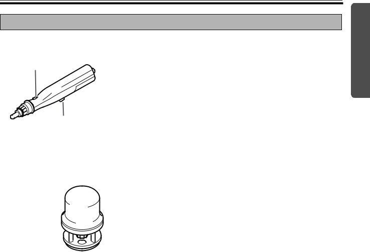
Electronic Pen and Eraser
■ Electronic Pen (see page 25)
Pen button*
Pen holder lever
*When using the projector mode to operate the computer screen on the Interactive Panaboard screen and operating the pen while holding down the pen button achieves the same function as pressing the right mouse button.
■ Electronic Eraser (see page 26)
Eraser cover 
 Eraser cloth
Start You Before
17
Installing the Thermal Transfer Film
Installing the Thermal
Transfer Film
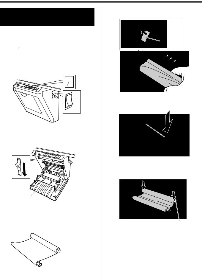
Install the thermal transfer film in the printer.
1 |
Set the power switch to on ( I ). |
• “ ” will flash on the Multi-Copy/Error |
Indicator when the thermal transfer film has run out.
• The screen will move to home position and stop.
ON
OFF
2 |
Push down the printer open lever and open |
the printer door. |
Printer door
3 Install the thermal transfer film.
1)Set the thermal transfer film, with the blue gear in front, on the right.
 Blue gear
2) Insert the blue shaft into the front left hole.
Blue shaft
3) Place the blue gear on the front right groove.
Blue gear
4)Place the white shaft on both sides of the back grooves.
White shaft
18

4 Tighten the film, then close the printer door.
1)Rotate the blue gear in the direction of the arrow to take up the slack on the film.
Blue gear
•If a slack remains, perform step 3-2) through 4-1) again.
2)Securely close the printer door by using both hands until a click is heard.
•“  ” flashing on the Multi-Copy/Error Indicator will go out.
Latches
Note
•If “  ” is still flashing after closing the printer door, make sure that the thermal transfer film has been installed properly and tightened.
•The printer door should be closed to make copies properly. Confirm both latches are locked.
Loading Copy Paper
Loading Copy Paper
It is possible to load up to 40 sheets of A4 (Letter*) size copy paper [assuming a paper weight of 80 g/m2 (20 lb.)].
Note that only A4 (Letter*) size paper may be used. When the unit is first used or when “  ” flashes on the Multi-Copy/Error Indicator to indicate that the unit is out of paper, load copy paper as described below.
* Letter size is for U.S.A. and Canada models.
Notes on Loading Copy Paper
Follow the guidelines below to ensure smooth and accurate printing by the unit.
•Only use A4 (Letter) size copy paper having a weight of 60 g/m2 (16 lb.) to 90 g/m2 (24 lb.) as the copy paper for this unit.
•Do not simultaneously load paper of varying type and thickness as this may result in paper jams.
•Before adding copy paper, be sure to remove all the copy paper remaining inside the unit’s paper cover. (Note that copy paper will slightly resist being removed, but may be pulled out without problems.) After removing the copy paper, stack the removed paper together with the new paper, fan it thoroughly, square it and reload.
DO NOT USE THE FOLLOWING TYPES OF PAPER
•Extremely smooth or glossy paper
•Coated paper
•Thermal paper
•Paper that is printed on one side
•Wrinkled paper, creased paper, etc.
1Set the power switch to on ( I ).
•“  ” will flash on the Multi-Copy/Error Indicator when copy paper has run out.
•The screen will move to home position and stop.
ON
OFF
Using
19
Loading Copy Paper
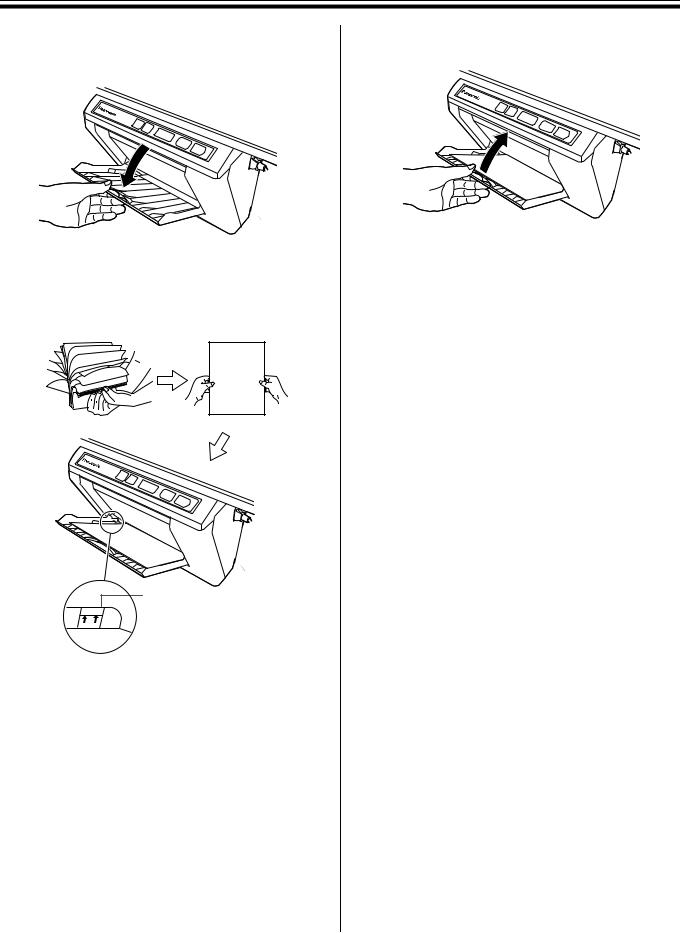
2 |
Pull the paper cover forward as shown in the |
figure. |
4 Close the paper cover until a click is heard.
3 |
To prevent paper jams such as those caused |
by multiple sheets feeding at once, fan the |
paper thoroughly, square it, align it with the guide inside, and insert as far as it will go.
Guide
 Maximum paper limit
Note
•Only use A4 (Letter*) size copying paper having a weight of 60 g/m2 (16 lb.) to 90 g/m2 (24 lb.) as the copy paper for this unit.
*Letter size is for U.S.A and Canada models.
•Do not stack more copy paper in the unit than the maximum paper limit indicated by the guide (see the above figure) as this may result in paper jams. [Note that the unit can hold about 40 sheets of paper having a weight of 80 g/m2 (20 lb.).]
Note
•Close the paper cover, or the unit will not work properly.
•The paper cover should be closed to make copies properly. Confirm the both latches are locked.
20
Making Copies
Making Copies
This section describes how to copy text and illustrations drawn on the screen.
1 |
Set the power switch to on ( I ). |
• “ ” will light on the Multi-Copy/Error |
Indicator to indicate that the unit is ready to copy.
• The screen will move to home position and stop.
ON
OFF
2 |
Press the |
|
(Copy Key). |
|
|||
|
|||
• Text and illustrations on the screen will be |
|||
copied and copies emerge from the output port.
• The output port can hold up to 10 sheets of copy paper. (Note that exceeding the output port’s capacity may result in paper jams.)
• For details on making multiple copies and so on, refer to “Copy Types and Procedures” on this page.
Note
•Do not use paper that has been copied on one side by this printer as copy paper in this unit or in any other copiers or printers as this may result in dirty rollers, degradation of printing quality, paper jams, and streaks and smudges on output paper.
•Copy quality increases with the thickness of the drawn line. To ensure quality copies, please use the markers (big).
•The markers for interactive (small) draw thin lines. The quality of the copies may be reduced when these markers are used.
•Do not write on the back side of the output paper from this unit. The printed ink may be transferred underneath the paper.
•Text or images in shades of yellow will not copy.
Copy Types and Procedures
[A]Copying the front of the screen
1)Press  .
.
[B]Copying the back of the screen
1)Press  to move the screen to be copied to the front.
2)Press  .
.
[C]Making multiple copies (up to 9)
1)Select the number of copies (1 to 9) by pressing  as necessary.
2)Press  .
.
•Press  to stop copying in mid-operation.
[D]Making 2-screen copies
Copying the front and back of the screen on a single sheet of paper
1) Press  .
.
Using
21

Replacing the Thermal Transfer Film
Replacing the Thermal
Transfer Film
The unit is capable of producing about 15 more copies when the Contrast/Remaining Film Indicator begins to flash. The unit has run out of thermal transfer film and can no longer make copies when the Multi-Copy/Error Indicator flashes “  ”. Separately available replacement film (UG-6001) may be purchased from the dealer where you purchased the unit. Thermal transfer film is replaced as follows.
Notes on Replacing Thermal Transfer Film
•Only use the designated product (UG-6001) from Panasonic as the replacement film. (Note that using another type of replacement film may result in degraded printing quality or damage to the unit.)
•Thermal transfer film is disposable. Dispose of used thermal transfer film as “burnable” or “nonrecyclable” rubbish.
•A negative of the copied image will remain on the thermal transfer film. To protect the security of your information, we recommend cutting up the used thermal transfer film with scissors or shredder before disposing of it.
1Push down the printer open lever to open the printer door, and remove the used film.
Note
•If “  ” is still flashing after closing the printer door, make sure that the thermal transfer film has been installed properly and tightened.
•The printer door should be closed to make copies properly. Confirm both latches are locked.
2 |
Refer to steps 3 and 4 in the section of |
“Installing the Thermal Transfer Film” on page |
|
|
18. |
22

Paper Jams
Paper Jams
Remove paper jams by the following procedure when copy paper does not come out of the output port or when “ 
 ” flashes on the Multi-Copy/Error Indicator.
1 |
Push down the printer open lever to open the |
printer door. |
2 Removehands. the thermal transfer film with both
3 Remove the jammed paper.
Jammed paper
4 |
Install the thermal transfer film. |
• Refer to steps 3 and 4 in the section of |
“Installing the Thermal Transfer Film” on page 18.
• “  ” flashing on the Multi-Copy/Error Indicator will go out.
Note
•If “  ” is still flashing after closing the printer door, make sure that the thermal transfer film has been installed properly and tightened.
•The printer door should be closed to make copies properly. Confirm both latches are locked.
If the flashing “  ” does not go out after the foregoing procedure has been performed; this may indicate that the paper feeder is not functioning properly.
Reload the copy paper by following the steps given below.
1 Turn the power off.
ON
OFF
2 |
Open the paper cover and remove all the copy |
paper remaining inside the unit’s paper cover. |
Note
•The copy paper will slightly resist being removed, but may be pulled out without problems.
Using
23

Paper Jams
3 |
To prevent paper jams such as those caused |
by multiple sheets feeding at once, fan the |
paper thoroughly, square it, align it with the guide inside, and insert as far as it will go.
Guide
 Maximum paper limit
Note
•Do not stack more copy paper in the unit than the maximum paper limit indicated by the guide (see figure) as this may result in paper jams. [Note that the unit can hold about 40 sheets of paper having a weight of 80 g/m2 (20 lb.).]
4 Close the paper cover until a click is heard.
Note
•Close the paper cover, or the unit will not work properly.
•The paper cover should be closed to make copies properly. Confirm the both latches are locked.
5 |
Turn the power on. |
• “ ” will light on the Multi-Copy/Error Indicator |
to indicate that the unit is ready to copy.
• The screen will move to home position and stop.
ON
OFF
24
Setting the Electronic Pen and Eraser
Setting the Electronic
Pen and Eraser
Setting the Electronic Pen
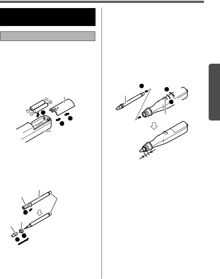
1 |
Remove the battery cover on the pen holder, |
insert the batteries as shown in the figure, and |
re-attach the battery cover.
• Always use “LR03 (AAA size)” (alkaline) batteries and be sure that their polarity is properly oriented.
• Do not mix old and new, different type batteries when replacing batteries.
Battery cover
|
2 |
|
1 |
|
3 |
|
Pen holder |
2 |
Remove the temporal cap, and set the cap |
and adaptor to the marker for interactive. |
•Securely push the adaptor into the marker for interactive as far as it will go.
•Do not remove the color identification cap on the back end of the marker.
Marker for interactive
Remove the
temporal cap.
Color identification cap
1
Adaptor
Cap
2
3
3 |
Rotate the pen holder lever to the release |
position, insert the marker for interactive, and |
then return the pen holder lever to the lock position.
• Lock the pen holder lever while inserting the marker all the way into the pen holder until you hear a buzzing sound.
Detection of the marker color may not work well unless the marker is inserted fully into the pen holder.
• Do not set the marker near the Interactive Panaboard while using the interactive function as this may appear unnecessary streaks not written on the computer screen.
2 |
Inserting |
Marker for |
3 Locking |
interactive |
|
|
1 Releasing |
|
Pen holder lever |
2 - 3 mm (1/16" - 2/16")
Note
•Press down firmly with the point of the Electronic Pen on the screen film until you hear a buzzing sound.
•For precise positioning, keep the Electronic Pen perpendicularly to the screen during use. Inclined pen angle will cause the shift of position.
Using
25
Setting the Electronic Pen and Eraser
Setting the Electronic Eraser
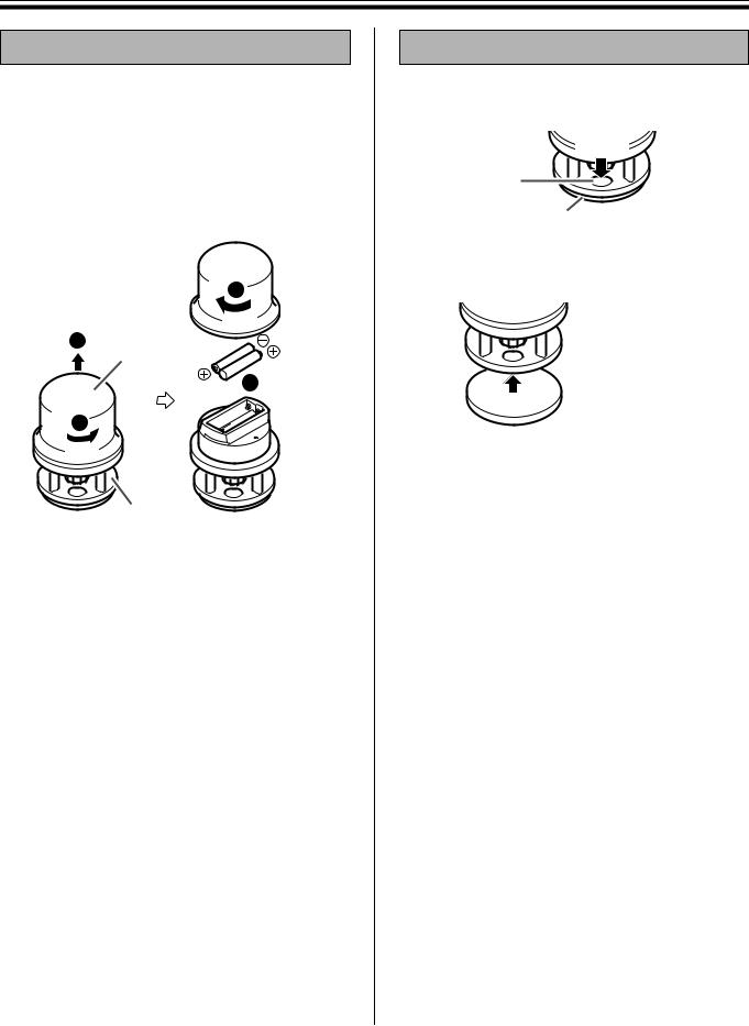
1 |
Remove the eraser cover, insert the batteries |
as shown in the figure, and re-attach the |
eraser cover.
•Always use “LR03 (AAA size)” (alkaline) batteries and be sure that their polarity is properly oriented.
•Do not mix old and new, different type batteries when replacing batteries.
4
2
Eraser cover

 3
3
1
Electronic eraser
Note
•Press down firmly with the eraser cloth of the Electronic Eraser on the screen film until you hear a buzzing sound.
Replacing the Eraser Cloth
1 |
Remove the eraser cloth by pushing through |
the hole in the Electronic Eraser. |
|
|
Press |
|
Hole |
|
Eraser cloth |
2 |
Attach a new eraser cloth by pressing around |
the edge. |
 New eraser cloth
26

Installing Drivers and Software
Installing Drivers and
Software
Drivers and software must be installed in your computer to use the interactive function, printer and TWAIN driver.
For the information of the interactive function and Panasonic-DMS, refer to “Features” on page 4.
System Requirements
Computer |
IBM PC/AT or compatible machine |
|
with a CD-ROM drive |
||
|
||
|
|
|
CPU |
Pentium® II or higher processor |
|
|
|
|
Interface |
USB 2.0 or USB 1.1*1 |
|
OS |
Windows® 98*2 / Windows Me*3 / |
|
Windows 2000*4 / Windows XP*5 |
||
|
64 MB or more (Windows 98 / |
|
Memory |
Windows Me) |
|
128 MB or more (Windows 2000) |
||
|
||
|
256 MB or more (Windows XP) |
|
|
|
|
HD |
At least 100 MB free space (except |
|
saving space for data files) |
||
|
||
|
|
*1 This electronic board does not function with Hi-Speed USB 2.0. Even if using a computer equipped with HiSpeed USB 2.0, this electronic board functions with Full Speed USB 2.0.
*2 Microsoft Windows 98 operating system (hereafter Windows 98)
*3 Microsoft Windows Millennium Edition operating system (hereafter Windows Me)
*4 Microsoft Windows 2000 operating system (hereafter Windows 2000)
*5 Microsoft Windows XP operating system (hereafter Windows XP)
Contents of CD-ROM
The provided CD-ROM includes the following.
•USB driver
•Printer driver
The printer driver allows the printer to print documents from your computer.
•TWAIN driver
•Panasonic-DMS software
Panasonic Document Management System (Panasonic-DMS) uses the TWAIN driver to scan images drawn on the screen. The PanasonicDMS has a capability of managing documents (image files).
•Interactive Panaboard Software
In order to use the interactive functions, it is necessary to install the Interactive Panaboard Software. The software cannot be used with the TWAIN driver.
•Panasonic-DMS manual
•Interactive Panaboard operating instructions
Notes when connecting the electronic board to a computer
•First install the USB, printer and TWAIN driver to your computer, then connect the electronic board to the computer (refer to “Installing Drivers / Interactive Panaboard Software”).
•If you connect the electronic board to a USB hub, it is not guaranteed to work.
•Do not connect two or more Panasonic electronic boards to a computer. It may cause the computer operation to become unstable.
•Use the USB cable provided with the unit.
Using
27
Installing Drivers and Software
Installing Drivers / Interactive
Panaboard Software
The USB, printer, TWAIN driver and Interactive Panaboard Software are installed in your computer by following procedures.
Note
•Do not yet connect a USB cable to the electronic board.
1Power on your computer and start Windows*1.
•Log on as an administrator for Windows 2000 or Windows XP.
*1 Microsoft Windows operating system (hereafter Windows)
2 Insert the CD-ROM into the CD-ROM drive. The Setup window appears automatically.
• Depending on the operating system or the settings that you are using, the Setup window may not appear automatically.
In such a case, execute “Menu.exe” in the CD-ROM from the Explorer.
3 When “Welcome” window appears, click
[Next].
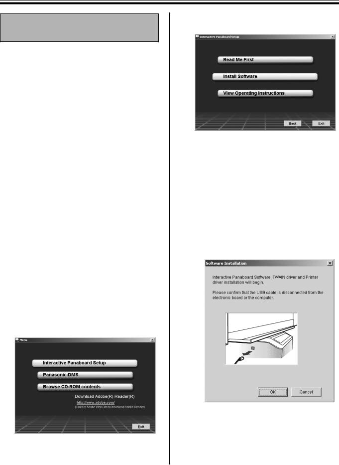
4 Click [Interactive Panaboard Setup].
•To install the Panasonic-DMS software, click
[Panasonic-DMS] (see page 30).
•To read the operating instructions in the provided CD-ROM, the Adobe Reader or Acrobat Reader must be installed in your computer. It can be downloaded from the Adobe's Web site if Internet is available.
5
6
7
Click [Install Software].
Read ”End-User License Agreement” carefully and click [Yes].
When the following window appears, check that the electronic board is not connected to your computer and click [OK].
•If the USB cable is connected to the electronic board, remove it and click [OK].
•For Windows 98 or Windows Me, a floppy disk or CD-ROM for installing the operating system may be required.
•If the screen prompts to restart Windows, restart Windows.
28

Installing Drivers and Software
8 When the following window appears after files are copied, power the electronic board on, and connect the USB cable provided from the electronic board to your computer.
Note
•If the electronic board is powered on with connecting the USB cable when the installation is completed and [Exit] is clicked in the setup window, the Interactive Panaboard Software is automatically started in Windows 2000 / Windows XP.
(For the detailed information, refer to “Starting the Interactive Panaboard Software” on page 33.)
Using
9
10
Follow the on-screen instructions if the wizard windows appear.
•If the wizard window is displayed to select the file (##.inf) for the printer driver in Windows XP, select “windows\inf\oem##.inf”.
•If the wizard window is displayed to connect to the Windows Update in Windows XP SP2, select [No].
•If the warning window is displayed in Windows 2000 / Windows XP, select [Yes] or
[Continue Anyway] to continue the installation.
•The new hardware wizard windows may be displayed several times depending on the operating system.
•For Windows 98 or Windows Me, a floppy disk or CD-ROM for installing the operating system may be required.
When the installation is completed, click [OK].
•Interactive Panaboard group is registered in the Panasonic of the Programs menu.
•The following is installed in the Interactive Panaboard group.
-Interactive Panaboard (application)
-Interactive Panaboard Help
-Interactive Panaboard Uninstall
-Operating Instructions
29
Installing Drivers and Software
Installing the Panasonic-DMS
Software
When Panasonic-DMS is already installed, leave it (do not uninstall it) and install the new software in the same folder to overwrite it.
1 Power on your computer and start Windows.
• Log on as an administrator for Windows 2000 or Windows XP.
2 Insert the CD-ROM into the CD-ROM drive. The Setup window appears automatically.
•Depending on the operating system or the settings that you are using, the Setup window may not appear automatically.
In such a case, double-click “Menu.exe” in the CD-ROM from the Explorer.
3 When “Welcome” window appears, click
[Next].
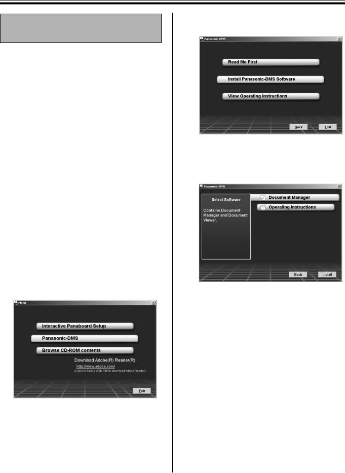
4 Click [Panasonic-DMS].
•To install the USB, printer, TWAIN driver and Panasonic Interactive Software, click
[Interactive Panaboard Setup] (see page 28).
•To read the operating instructions in the provided CD-ROM, the Adobe Reader or Acrobat Reader must be installed in your computer. It can be downloaded from the Adobe's Web site if Internet is available.
5
6
7
8
9
Click [Install Panasonic-DMS Software].
Click [Install].
•To install the Panasonic-DMS Manual, check the [Operating Instructions] check box.
Read “End-User License Agreement” carefully and click [Yes].
Follow the on-screen instructions when messages appear.
When the setup process is completed, restart Windows.
•About the Panasonic-DMS, refer to the Document Management System operating instructions in the CD-ROM.
30
 Loading...