


TH-37PA20
Progressive
Plasma Television
Operating Instructions
Model No.
English
TQBC0616-2
TH-37PA20
TH-42PA20
TH-42PA25
For assistance, please call : 1-888-VIEW-PTV(843-9788)
or send e-mail to : consumerproducts@panasonic.com
or visit us at www.panasonic.com (U.S.A)
For assistance, please call : 787-750-4300
or visit us at www.panasonic.com (Puerto Rico)
For assistance, please call : 1-800-561-5505
or visit us at www.panasonic.ca (Canada)
Before connecting, operating or adjusting this product, please read these instructions completely.
Please keep this manual for future reference.
A
C
T
I
O
N
123
456
78
0
9
T
V
D
T
V
C
B
L
AUX
D
V
D
V
C
R
D
B
S
RCV
R
POWER
CH
CH
VOL VOL
PLAY
R-TUNE PROG
GUIDE
RECALL
SAP
PAGEEXIT
PIP SPLIT MOVE SWAP
STOPPAUSE
REC
PIP MAX
FF
PIP MIN
REW
PC
MENU
FREEZE
TV/VCR
PIP CH
VCR CH
SEARCH
OPEN/CLOSE
M
U
T
E
A
S
P
E
C
T
T
V
/
V
I
D
E
O
L
I
G
H
T
2
WARNING:1) To prevent electric shock, do not remove cover. No user serviceable parts inside. Refer servicing to
qualified service personnel.
2) Do not remove the grounding pin on the power plug. This apparatus is equipped with a three pin
grounding-type power plug. This plug will only fit a grounding-type power outlet. This is a safety feature.
If you are unable to insert the plug into the outlet, contact an electrician.
Do not defeat the purpose of the grounding plug.
WARNING: To reduce the risk of fire or electric shock, do not expose this apparatus to rain or moisture.
Do not place liquid containers (flower vase, cups, cosmetics, etc.) above the set. (including on
shelves above, etc.)
WARNING: To reduce the risk of electric shock, do not remove cover or back.
No user-serviceable parts inside. Refer servicing to qualified service personnel.
The lightning flash with
arrow-head within a triangle
is intended to tell the user
that parts inside the product
are a risk of electric shock to
persons.
The exclamation point within
a triangle is intended to tell
the user that important
operating and servicing
instructions are in the papers
with the appliance.
WARNING
RISK OF ELECTRIC SHOCK
DO NOT OPEN
Manufactured under license from BBE Sound, Inc.
Licensed by BBE Sound, Inc. under USP4638258, 5510752 and 5736897.
BBE and BBE symbol are registered trademarks of BBE Sound, Inc.
Note:
Do not allow a still picture to be displayed for an extended period, as this can cause a permanent after-
image to remain on the Plasma television.
Examples of still pictures include logos, video games, computer images, teletext and images displayed in
4:3 mode.
Trademark Credits
•
VGA is a trademark of International Business Machines Corporation.
•
Macintosh is a registered trademark of Apple Computer, USA.
•
S-VGA is a registered trademark of the Video Electronics Standard Association.
Even if no special notation has been made of company or product trademarks, these trademarks have been fully
respected.

3
1) Read these instructions.
All the safety and operating instructions should be read before the appliance is operated.
2) Keep these instructions.
The safety and operating instructions should be retained for future reference.
3) Heed all warnings.
All warnings on the appliance and in the operating instructions should be adhered to.
4) Follow all instructions.
All operating and use instructions should be followed.
5) Do not use this apparatus near water.
For example, near a bathtub, wash bowl, kitchen sink, or laundry tub, in a wet basement, or near a swimming pool, and
the like.
6) Clean only with dry cloth.
Do not use liquid cleaners or aerosol cleaners. Use a dry cloth for cleaning.
7) Do not block any ventilation openings. Install in accordance with the manufacturer’s instructions.
Slots and Openings in the cabinet are provided for ventilation and to ensure reliable operation of the product and to
protect it from overheating. The openings should never be blocked by placing the product on a bed, sofa, rug, or other
similar surface.
8) Do not install near any heat sources such as radiators, heat registers, stoves, or other apparatus (including amplifiers)
that produce heat.
This product should not be placed in a built-in installation such as a bookcase or rack unless proper ventilation is
provided or the manufacturer’s instructions have been adhered to.
9) Do not defeat the safety purpose of the polarized or grounding-type plug. A polarized plug has two blades with one wider
than the other. A grounding type plug has two blades and a third grounding prong. The wide blade or the third prong are
provided for your safety. If the provided plug does not fit into your outlet, consult an electrician for replacement of the
obsolete outlet.
10) Protect the power cord from being walked on or pinched particularly at plugs, convenience receptacles, and the point
where they exit from the apparatus.
11) Only use attachments / accessories specified by the manufacturer.
12) Use only with the cart, stand, tripod, bracket, or table specified by the manufacturer, or sold with the
apparatus. When a cart is used, use caution when moving the cart / apparatus combination to avoid
injury from tip-over.
Quick stops, excessive force, and uneven surfaces may cause the appliance and cart combination
to overturn.
13) Unplug this apparatus during lightning storms or when unused for long periods of time.
This will prevent damage to the product due to lightning and power-line surges.
14) Refer all servicing to qualified service personnel. Servicing is required when the apparatus has been damaged in any
way, such as power-supply cord or plug is damaged, liquid has been spilled or objects have fallen into the apparatus,
the apparatus has been exposed to rain or moisture, does not operate normally, or has been dropped.
15) To prevent electric shock, ensure the grounding pin on the AC cord power plug is securely connected.
Important Safety Instructions

4
Dear Panasonic Customer
Welcome to the Panasonic family of customers. We hope that you will have many years of enjoyment
from your new Plasma TV.
To obtain maximum benefit from your set, please read these Instructions before making any adjustments,
and retain them for future reference.
Retain your purchase receipt also, and record the model number and serial number of your set in the
space provided on the back cover of these instructions.
Visit our Panasonic Web Site for USA : www.panasonic.com
for Puerto Rico : www.panasonic.com
for Canada : www.panasonic.ca
For assistance, please call : 1-888-VIEW-PTV(843-9788)
or send e-mail to : consumerproducts@panasonic.com
or visit us at www.panasonic.com (U.S.A)
For assistance, please call : 787-750-4300
or visit us at www.panasonic.com (Puerto Rico)
For assistance, please call : 1-800-561-5505
or visit us at www.panasonic.ca (Canada)
FCC STATEMENT:
NOTE: This equipment has been tested and found to comply with the limits for a Class B digital device, pursuant to Part
15 of the FCC Rules. These limits are designed to provide reasonable protection against harmful interference in a
residential installation. This equipment generates, uses and can radiate radio frequency energy and, if not installed
and used in accordance with the instructions, may cause harmful interference to radio communications. However,
there is no guarantee that interference will not occur in a particular installation. If this equipment does cause
harmful interference to radio or television reception, which can be determined by turning the equipment off and on,
the user is encouraged to try to correct the interference by one or more of the following measures:
• Reorient or relocate the receiving antenna.
• Increase the separation between the equipment and receiver.
• Connect the equipment into an outlet on a circuit different from that to which the receiver is connected.
• Consult the dealer or an experienced radio/TV technician for help.
This device complies with Part 15 of the FCC Rules. Operation is subject to the following two conditions: (1) This device
may not cause harmful interference, and (2) this device must accept any interference received, including interference that
may cause undesired operation.
FCC CAUTION:
To assure continued compliance and possible undesirable interference, the provided ferrite cores must be used
when connecting this plasma television to video equipment; and maintain at least 40cm spacing to other peripheral
devices. Refer to instructions on pages 9, 10, 11, 12, 13, 14, 17, 18 and 19.
Any changes or modifications to this TV not expressly approved by Matushita Electric Corporation of America
could result harmful interference and would void the user’s authority to operate this device.
FCC Declaration of Conformity
Model No.TH-37PA20
TH-42PA20
TH-42PA25
Responsible Party: Matsushita Electric Corporation of America
One Panasonic Way, Secaucus, NJ 07094
Contact Source: Panasonic Consumer Electronics Company
1-888-843-9788
email: consumerproducts@panasonic.com
CANADIAN NOTICE: For Models TH-37PA20 and TH-42PA20
This Class B digital apparatus complies with Canadian ICES-003.

5
SURROUND ............................................................... 32
SPEAKERS ................................................................. 32
CHANNELS Adjustment .............................................. 33
CHANNEL SCAN ........................................................ 33
FAVORITE CHANNELS Selection .............................. 33
Selecting option menus in OTHER ADJ...................... 34
PRESET CAPTION ..................................................... 34
MANUAL CAPTION .................................................... 35
INPUT LABEL ............................................................. 35
TIMER ............................................................................ 36
SLEEP ........................................................................ 36
TIMER1 and TIMER2 .................................................. 36
CLOCK SET ................................................................ 38
LOCK Feature ............................................................... 39
CREATE CODE FIRST ............................................... 39
CODE .......................................................................... 39
LOCK SET ...................................................................39
CHANNEL ................................................................... 40
V-CHIP SET ................................................................ 40
U.S. TV PROGRAMS.................................................. 41
U.S. MOVIES .............................................................. 42
Canadian English ........................................................ 43
Canadian French ........................................................ 44
Blocking Message ....................................................... 45
HOW LONG? .............................................................. 45
Picture in Picture Operation........................................ 46
Split Screen ...................................................................48
ASPECT Controls ......................................................... 50
PC MENU....................................................................... 51
PICTURE Adjustment ................................................. 51
Adjusting PICTURE POSITION/SIZE ......................... 52
SYNC .......................................................................... 53
H-FREQ. (kHz)/V-FREQ. (Hz) .....................................53
Operating peripheral equipment using the remote control .....
54
Programming The Illuminated Remote Control
Using Access Codes ........................................ 54
Programming Without A Code
(When the code is not known) ......................... 55
Infrared Codes Index .................................................. 56
Mode Operational Key Chart ...................................... 59
Troubleshooting Chart................................................. 61
VIDEO/COMPONENT/PC/DVD input signals .............. 62
Specifications ............................................................... 63
Table of Contents
Important Safety Instructions ....................................... 3
FCC STATEMENT ........................................................... 4
Safety Precautions ......................................................... 6
Installation ...................................................................... 8
Receiver Location ......................................................... 8
Optional External Equipment ........................................ 8
Remote Control Battery Installation .............................. 8
Accessories .................................................................... 9
Cable Connection......................................................... 10
Antenna Connection ................................................... 11
Connecting Headphones / Earphones .........................11
Front Control Panel ..................................................... 12
Optional Equipment Connections ............................... 12
Cable Box Connection ........................................ 12
VCR Connection ................................................. 13
VCR and Cable Box Connection ......................... 14
Digital TV - Set-Top Box (DTV-STB) or DVD Connection
.. 15
Amplifier Connection (TO AUDIO AMP) ............... 15
Program Out Connection (PROG OUT) .............. 16
How to connect the DIGITAL IN Terminals .................. 16
Connecting a Digital Set-Top-Box to
DIGITAL IN................................................ 16
PC Input Terminals connection ................................... 17
Power ON / OFF ............................................................ 18
AC cord connection..................................................... 18
How to Turn the Power On.......................................... 18
Menu Language Selection .......................................... 18
Cable TV / VHF, UHF and CATV................................... 19
Cable TV ..................................................................... 19
VHF, UHF and CATV................................................... 19
Location of Controls .................................................... 20
Illuminated Remote Control ........................................ 20
Basic Menu Operations ............................................... 22
SET UP Operation ........................................................ 24
MENU Languages ....................................................... 24
ANTENNA Selection ................................................... 24
cc
ON MUTE
cc
MODE (Closed Captions) ............ 24
Selecting option menus in OTHER ADJ...................... 25
MODE Selection ......................................................... 26
AUTO PROGRAM....................................................... 26
MANUAL PROGRAM.................................................. 26
AUTO POWER ON ..................................................... 27
CHAN BANNER .......................................................... 27
SIDE BAR ..........................................................................
27
POWER SAVE ............................................................ 28
PICTURE Adjustment ................................................... 28
PICTURE MODE ........................................................ 28
COLOR / TINT / BRIGHTNESS / PICTURE /
SHARPNESS / NORMAL ............................... 28
Selecting option menus in OTHER ADJ...................... 29
COLOR TEMP (Temperature) / NATURAL COLOR /
VIDEO NR / 3D Y/C FILTER ............................ 29
COLOR MATRIX ......................................................... 29
FREEZE ...................................................................... 30
Audio Adjustment ........................................................ 31
Selecting STEREO/SAP/MONO ................................. 31
Selecting BASS / TREBLE / BALANCE / NORMAL.... 31
Selecting option menus in OTHER ADJ...................... 31
AI SOUND................................................................... 31
BBE VIVA / BBE .......................................................... 32

6
Safety Precautions
WARNING
Set up
Do not place the Plasma TV on sloped or unstable surfaces.
•
The Plasma TV may fall off or tip over.
Do not place any objects on top of the Plasma TV.
•
If water spills onto the Plasma TV or foreign objects get inside it, a short-circuit may occur which could result in fire or
electric shock. If any foreign objects get inside the Plasma TV, please consult an Authorized Service Center.
Do not cover the ventilation holes.
•
Doing so may cause the Plasma TV to overheat, which can cause fire or damage to the Plasma TV.
If using the pedestal, leave a space of 3
15
/
16
” (10 cm) or more at the top, left and right, 2
3
/
8
”
(6 cm) or more at the
bottom, and 2
3
/4” (7 cm) or more at the rear. If using some other setting-up method, leave a space of 3
15
/16” (10 cm)
or more at the top, bottom, left and right, and
3
/4” (1.9 cm) or more at the rear.
Avoid installing this product near electronic equipment that easily receives electromagnetic waves.
•
It may cause interference in image, sound, etc. In particular, keep video equipment away from this product.
AC Power Supply Cord
The Plasma TV is designed to operate on 120 V AC, 50/60 Hz.
Securely insert the power cord plug as far as it will go.
•
If the plug is not fully inserted, heat may be generated which could cause fire. If the plug is damaged or the wall socket
plate is loose, they should not be used.
Do not handle the power cord plug with wet hands.
•
Doing so may cause electric shocks.
Do not do anything that might damage the power cable. When disconnecting the power cable, hold the plug, not
the cable.
•
Do not make any modifications, place heavy objects on, place near hot objects, heat, bend, twist or forcefully pull the
power cable. Doing so may cause damage to the power cable which can cause fire or electric shock. If damage to the
cable is suspected, have it repaired at an Authorized Service Center.
If the Plasma TV will not be used for a long period of time, unplug the power cord from the wall outlet.
If problems occur during use
If a problem occurs (such as no picture or no sound), or if smoke or an abnormal odor is detected from the Plasma
TV, unplug the power cord immediately.
•
Continuous use of the TV under these conditions might cause fire or permanent damage to the unit. Have the TV
evaluated at an Authorized Service Center. Services to the TV by any unauthorized personnel are strongly discouraged
due to its high voltage dangerous nature.
If water or foreign objects get inside the Plasma TV, if the Plasma TV is dropped, or if the cabinet becomes damaged,
disconnect the power cord plug immediately.
•
A short may occur, which could cause fire. Contact an Authorized Service Center for any repairs that need to be made.

7
CAUTION
This Plasma TV is for use only with the following optional accessories. Use with any other type of optional
accessories may cause instability which could result in the possibility of injury.
(All of the following accessories are manufactured by Matsushita Electric Industrial Co., Ltd.)
•
Pedestal (included)................................................... TY-ST42PA20
•
Wall-hanging bracket (vertical) ................................. TY-WK42PV2W
Always be sure to ask a qualified technician to carry out set-up.
When using the Plasma TV
Do not bring your hands, face or objects close to the ventilation holes of the Plasma TV.
•
Top of the Plasma TV is usually very hot due to the high temperature of exhaust air being released through the ventilation
holes. Burns or personal injuries can happen if any body parts are brought too close. Placing any object near the top of the
TV could also result in heat damages to the object as well as to the TV if its ventilation holes are blocked.
Be sure to disconnect all cables before moving the Plasma TV.
•
Moving the TV with its cables attached might damage the cables which, in turn, can cause fire or electric shock.
Disconnect the power plug from the wall outlet as a safety precaution before carrying out any cleaning.
•
Electric shocks can result if this is not done.
Clean the power cable regularly to prevent it from becoming dusty.
•
Built-up dust on the power cord plug can increase humidity which might damage the insulation and cause fire. Unplug
the cord from the wall outlet and clean it with a dry cloth.
This Plasma TV radiates infrared rays, therefore it may affect other infrared communication equipment.
Install your infrared sensor in a place away from direct or reflected light from your Plasma TV.
Cleaning and maintenance
The front of the display panel has been specially treated. Wipe the panel surface gently using only a cleaning cloth
or a soft, lint-free cloth.
•
If the surface is particularly dirty, soak a soft, lint-free cloth in a weak detergent solution and then wring the cloth to
remove excess liquid. Use this cloth to wipe the surface of the display panel, then wipe it evenly with a dry cloth, of the
same type, until the surface is dry.
•
Do not scratch or hit the surface of the panel with fingernails or other hard objects. Furthermore, avoid contact with volatile
substances such as insect sprays, solvents and thinner, otherwise the quality of the surface may be adversely affected.
If the cabinet becomes dirty, wipe it with a soft, dry cloth.
•
If the cabinet is particularly dirty, soak the cloth in a weak detergent solution and then wring the cloth dry. Use this cloth
to wipe the cabinet, and then wipe it dry with a dry cloth.
•
Do not allow any detergent to come into direct contact with the surface of the Plasma TV.
If water droplets get inside the unit, operating problems may result.
•
Avoid contact with volatile substances such as insect sprays, solvents and thinner, otherwise the quality of the cabinet
surface may be adversely affected or the coating may peel off. Furthermore, do not leave it for long periods in contact
with articles made from rubber or PVC.
Note:
Do not allow a still picture to be displayed for an extended period, as this can cause a permanent after-image to remain
on the Plasma TV.
Examples of still pictures include logos, video games, computer images, teletext and images displayed in 4:3 mode.
Safety Precautions
8
Precaution on battery use
Incorrect installation can cause battery leakage and corrosion that
will damage the remote control transmitter.
Observe the following precautions:
1. Batteries should always be replaced as a pair. Always use new
batteries when replacing the old set.
2. Do not combine a used battery with a new one.
3. Do not mix battery types (example: “Zinc Carbon” with “Alkaline”).
4. Do not attempt to charge, short-circuit, disassemble, heat or burn
used batteries.
5. Battery replacement is necessary when remote control acts
sporadically or stops operating the TV set.
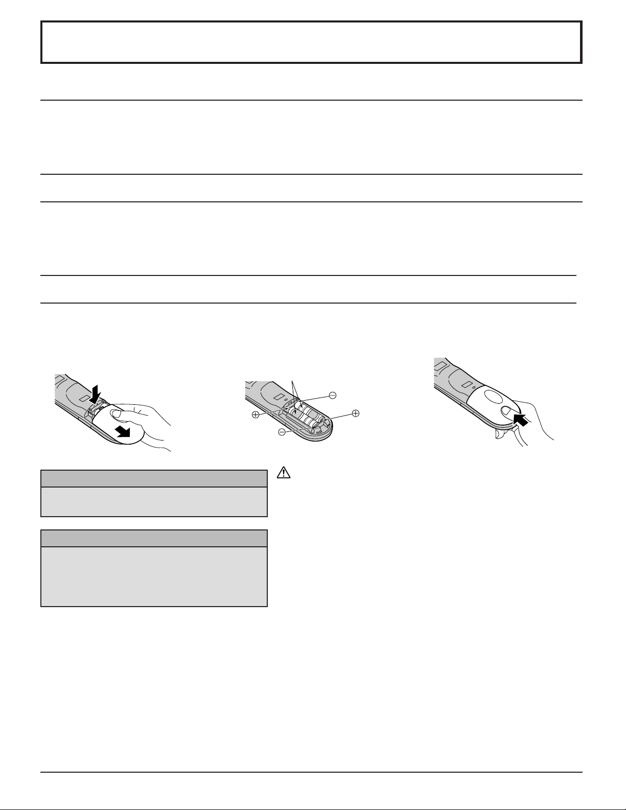
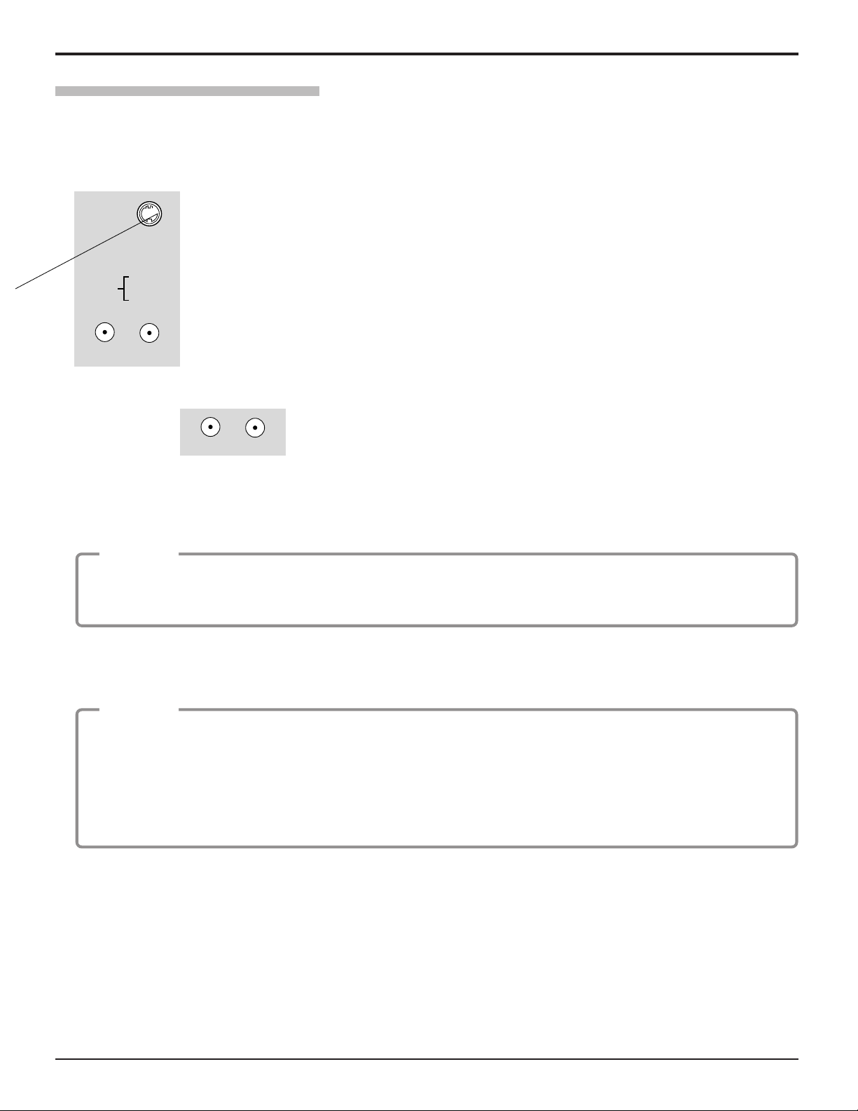
Requires two AA batteries.
1. Turn the Transmitter face down.
Remove top cover by pressing
down on marking and sliding cover
off in the direction indicated.
2. Install the batteries as shown in the
battery compartment. (Polarity + or
– must match the markings in the
compartment.)
3. Replace the cover and slide in
reverse until the lock snaps.
Two AA size
For frequent remote control users, replace old
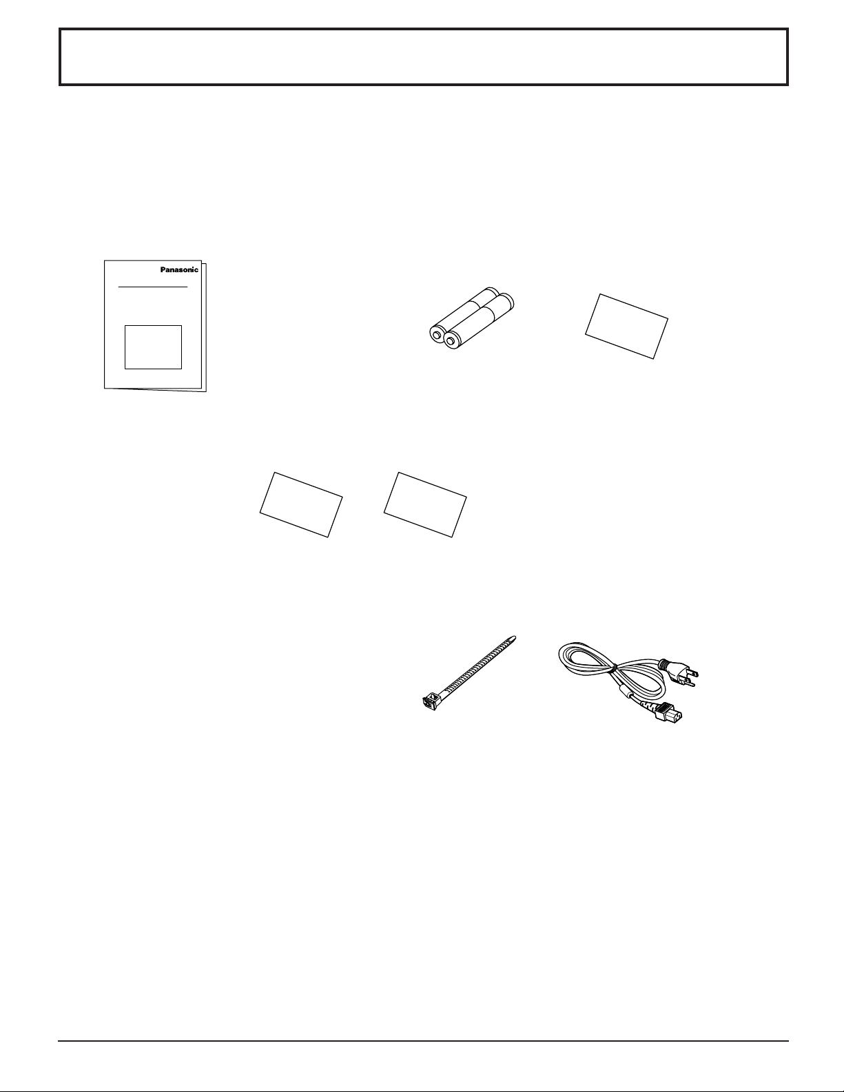
batteries with alkaline batteries for longer life.
Helpful Hints:
The Video/Audio connection between components can be made with shielded video and audio cables. For best performance,
video cables should utilize 75 ohm coaxial shielded wire. Cables are available from your dealer or electronic supply store.
Before you purchase any cables, be sure you know what type of output and input connectors your various components
require. Also determine the length of cable you will need.
Installation
Receiver Location
This unit is intended to be used with an optional stand or entertainment center. Consult your dealer for available options. Locate for
comfortable viewing. Avoid placing where sunlight or other bright light (including reflections) will fall on the screen.
Use of some types of fluorescent lighting can reduce remote control transmitter range.
Adequate ventilation is essential to prevent internal component failure. Keep away from areas of excessive heat or moisture.
Optional External Equipment
Whenever you remove the batteries, you may
need to reset the remote control infrared
codes. We recommend that you record the code
on page 56, prior to setting up the remote control.
Helpful Hints:
Remote Control Battery Installation
9
10
S VIDEO VIDEO
INPUT 3
L AUDIO R
PC
S-VIDEO
PC
CHANNELVOLUMEACTIONINPUT
HPJ
VIDEO
VIDEO
3
R AUDIO L
PROG OUT
COMPONENT VIDEO INPUT
S VIDEO
DIGITAL
IN
VIDEO
Y
P
B
L
R
L
R
ANT 1 ANT 2SPLIT
OUT
P
R
12
1
2
INPUT
TO AUDIO
AMP
AUDIO
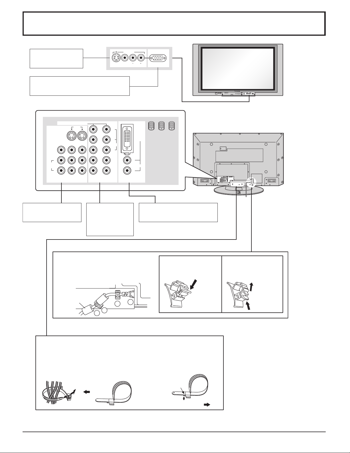
AV terminals
(see page 13,14,16)
COMPONENT
and Audio
Input terminals
(see page 15)
Front AV terminal
(see page 12)
From EXTERNAL monitor terminal
on Computer (see page 17)
DIGITAL(DVI) Input terminal
(see page 16)
VIDEO
1
3
2
4
Cable Connection
– Cable fixing bands
Secure any excess cables with bands as required.
To secure cables connected to Terminals, wrap the cable fixing band
around them then pass the pointed end through the locking block, as
shown in the figure.
While ensuring there is sufficient slack in cables to minimize stress
(especially in the power cord), firmly bind all cables with the
supplied fixing band.
To tighten:
To loosen:
Pull
Pull
Push the
catch
1. Connect power plug to the socket of
the main body.
2. Fix the left clamper.
3. Fix the right clamper.
4. Install the ferrite core.
How to fix: Fix by
pushing in till a clicking
sound is heard.
How to release: Pull up
while drawing the knob.
Ferrite core
(large size)
(supplied)
– AC cord fixing
11
PROG OUT
COMPONENT VIDEO INPUT
S VIDEO
DIGITAL
IN
VIDEO
Y
P
B
L
R
L
R
P
R
12
12
INPUT
VIDEO
TO AUDIO
AMP
AUDIO
ANT 1 ANT 2SPLIT
OUT
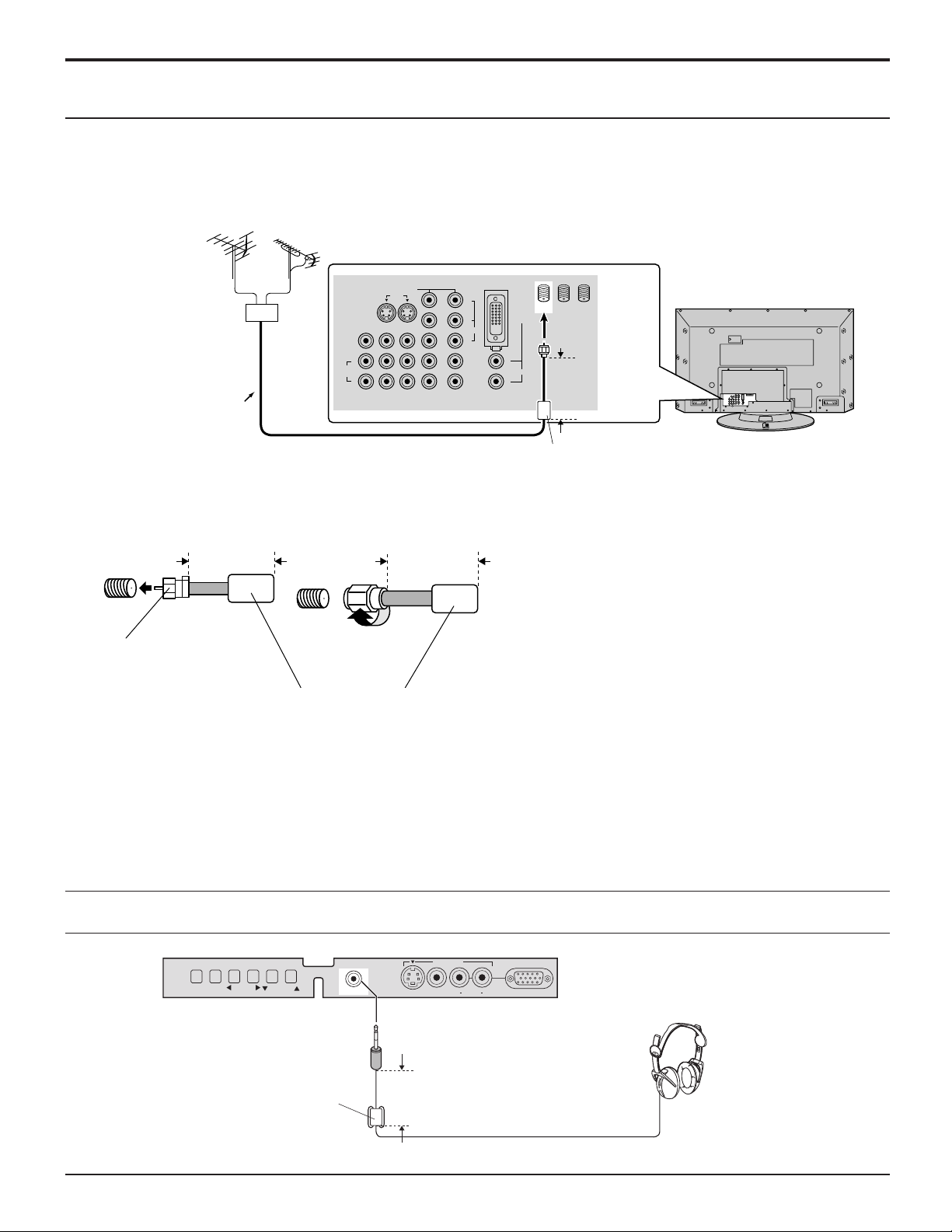
Notes:
(1) To obtain optimum quality picture and sound, an Aerial, the correct cable (75 Ohm coaxial) and the correct terminating
plug are required.
(2) If a communal Aerial system is used, you may require the correct connection cable and plug between the wall Aerial
socket and your television receiver.
(3) Your local Television Service Centre or Dealer may be able to assist you in obtaining the correct Aerial system for your
particular area and the accessories required.
(4) Any matters regarding Aerial installation, upgrading of existing systems or accessories required, and the costs incurred,
are the responsibility of you, the Customer.
Note: Certain cable systems offset some channels to
reduce interference or have Premium
(scrambled) channels. A cable converter box is
required for proper reception. Check with your
local Cable company for its compatibility
requirements.
Incoming Cable from
Home Antenna
Incoming Cable from
Cable Company
75 Ohm VHF/UHF
on back of TV
• For proper reception of VHF/UHF channels, an external antenna is required. For best reception, an outdoor antenna is
recommended. Antenna Mode must be set to TV.
• Incoming Cable from Home Antenna
Connect home antenna to ANT1 connection on back of television. Select TV mode and ANT1 in the SET UP menu.
( Cable Mode is preset at the factory. Antenna users must change to TV mode and select ANT1 in the Set Up Menu.)
VHF Aerial
UHF Aerial
Mixer
75 Ohm
Coaxial Cable
S VIDEO
CHANNELVOLUMEACTION INPUT
VIDEO
INPUT 3
L AUDIO R
PC
HPJ
Connect headphones / earphones as follows.
You can listen to sound from the headphone Jack.
(M3 plug)
(Optional)
Connecting Headphones / Earphones
Cable Connection
Less than
4” (10 cm)
Less than
4” (10 cm)
Ferrite core (large size)
(supplied)
Less than
4” (10 cm)
Ferrite core (large size)
(supplied)
Less than
4” (10 cm)
Ferrite core (small size)
(supplied)
F-Type Antenna
Adapter (supplied)
Antenna Connection
12
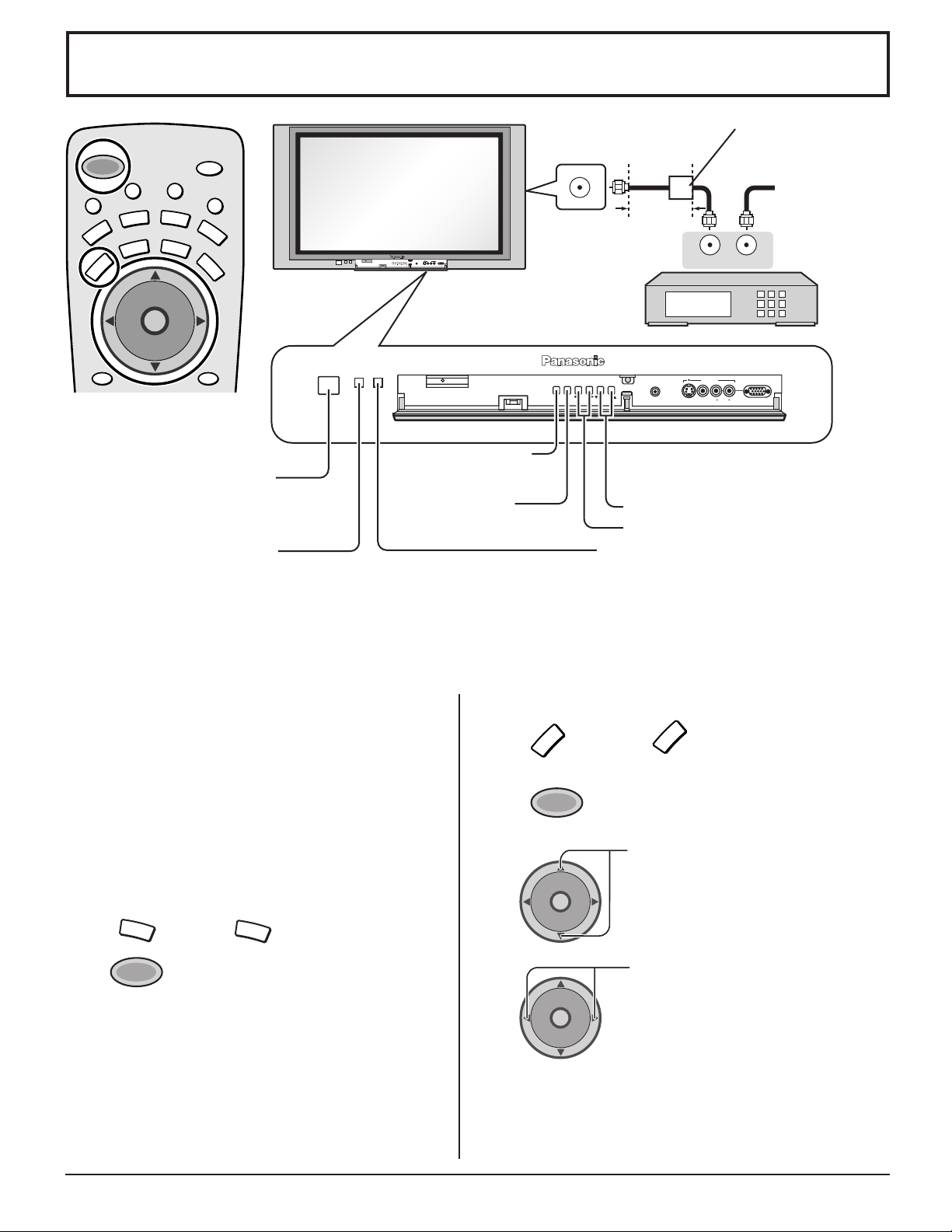
Follow this diagram when connecting your television to a cable box only.
Optional Equipment Connections
Note: The remote control must be programmed with supplied codes to operate the cable box (see page 58).
Procedure
1. Select ANT2 in the SET UP menu.
2. Tune the television to Channel 3 or Channel 4.
3. Using the cable box, tune to the premium cable channel you would like to view.
Note:
To use special features such as Favorite Channels and Channel Captions, ANT1 must be selected in the SET UP menu
(see page 24).
Viewing a premium (scrambled) cable channel
Cable Box Connection
ANT OUTPUT
ANT INPUT
PROG OUT
COMPONENT VIDEO INPUT
S VIDEO
DIGITAL
IN
VIDEO
Y
P
B
L
R
L
R
ANT 1 ANT 2SPLIT
OUT
P
R
12
12
INPUT
VIDEO
TO AUDIO
AMP
AUDIO
CABLE BOX
Incoming Cable
CONNECTIONS ON BACK OF TV
CABLES NOT
SUPPLIED
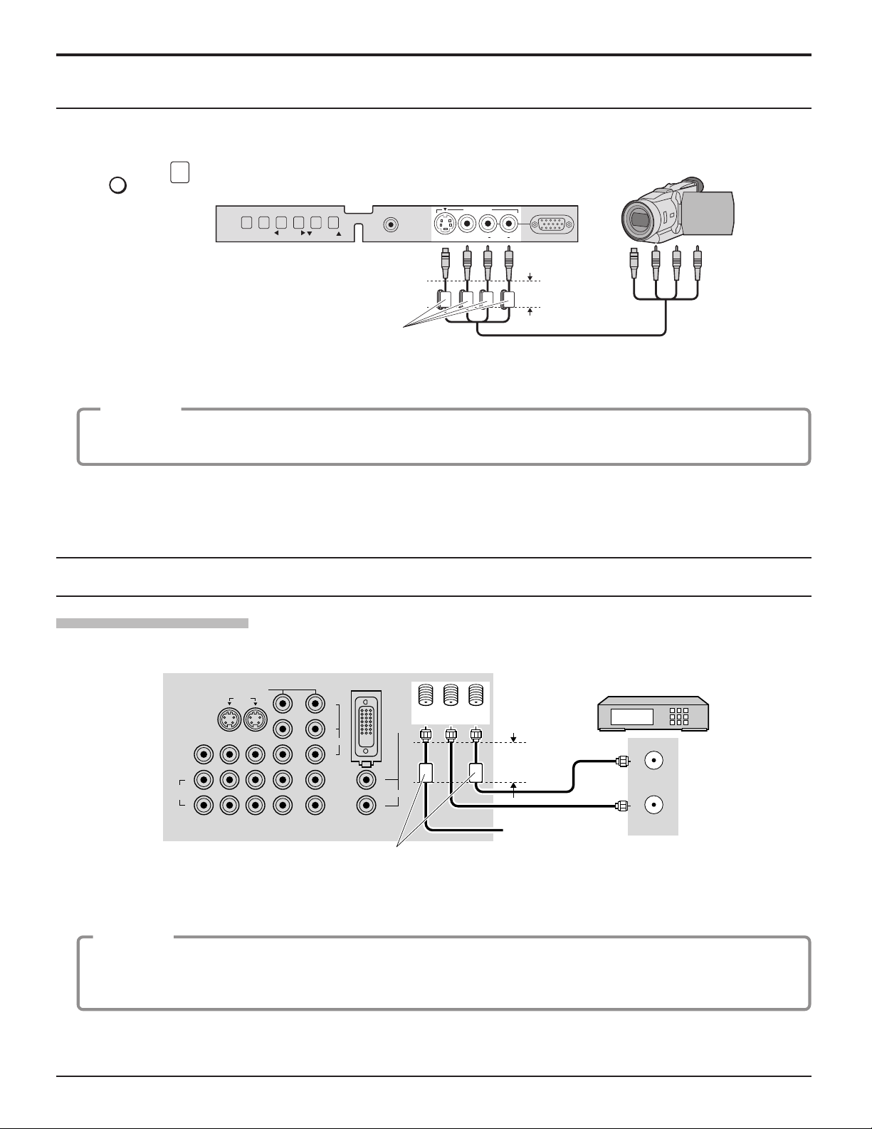
Push to open the front panel of the television to use the TV without remote control or to use the Audio/Video input jacks for
optional equipment.
Note:
The S-VIDEO connection provides higher quality picture. It overrides other VIDEO connections. Use INPUT 3, AUDIO L
and R with S-VIDEO connection.
A second VCR, video disc player, video game equipment and DSS equipment can also be connected to the video inputs.
See the optional equipment manual for details.
Front Control Panel
Press
TV/VIDEO
or
INPUT
to select VIDEO 3 input mode.
1. Connect equipment to front Audio/Video input jacks.
2. Operate optional equipment as instructed in equipment manual.
Procedure
Note:
The front control panel can be used to access menus and
switch video mode when the remote control is not
available.
CHANNELVOLUMEACTION INPUT
PC
HPJ
S VIDEO VIDEO
INPUT 3
L AUDIO R
CAMCORDER
Cable Connection
Less than
4” (10 cm)
Ferrite core (small size)
(supplied)
Less than
4” (10 cm)
Ferrite core (large size)
(supplied)
13
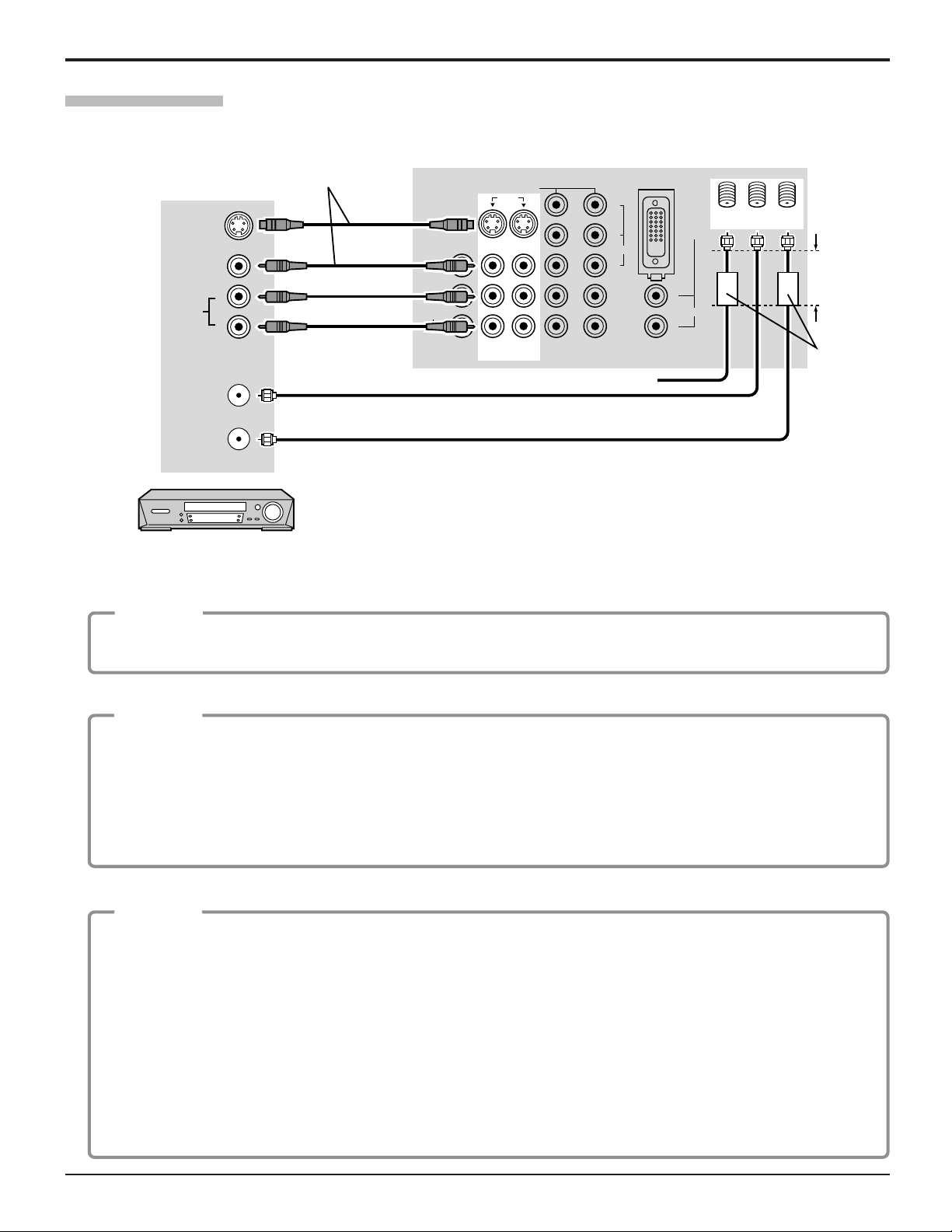
Cable Connection
Follow this diagram when connecting your television to a VCR only.
Note: The remote control must be programmed with supplied codes to operate the VCR (see page 56, 57).
VCR Connection
Procedure
1. Select ANT1 in the SET UP menu. (See page 24)
2. Tune the television to the television program you would like to view.
Viewing a television program
Procedure
• Option A
1.
Press the TV/VIDEO button on the remote control to select the video input (VIDEO 1, VIDEO 2, etc.) connected to your VCR.
2. Begin the video.
• Option B
1. Select ANT2 in the SET UP menu.
2. Tune the television to Channel 3 or 4, depending on your VCR.
3. Begin the video.
Viewing a video
Procedure
• Option A (Recording and viewing the same program)
1. Select ANT2 in the SET UP menu.
2. Tune the television to Channel 3 or 4, depending on your VCR.
3. Using the VCR, tune to the television program you would like to record.
4. Begin recording.
• Option B (Recording one program while viewing another program)
1. Select ANT1 in the SET UP menu.
2.
Press the TV/VIDEO button on the remote control to select the video input (VIDEO 1, VIDEO 2, etc.) connected to your VCR.
3. Using the VCR, tune to the television program you would like to record.
4. Begin recording.
5. Press the TV/VIDEO button on the remote control to switch back to TV mode.
6. Tune the television to the program you would like to view.
Recording a television program
PROG OUT
COMPONENT VIDEO INPUT
S VIDEO
DIGITAL
IN
VIDEO
Y
P
B
L
R
L
R
ANT 1 ANT 2
PR
12
12
INPUT
VIDEO
TO AUDIO
AMP
AUDIO
S-VIDEO
VIDEO
ANT INPUT
ANT OUTPUT
AUDIO
R
L
SPLIT
OUT
CONNECTIONS ON BACK OF TV
Incoming Cable
CABLES NOT SUPPLIED
VCR
Use either the S-Video or
the Video connection.
Ferrite core
(large size)
(supplied)
Less than
4” (10cm)
14
Cable Connection
Follow this diagram when connecting your television to both a VCR and a cable box.
Notes:
(1) Similar connections are available at the INPUT 1, 2, 3 input terminals.
Input 3 is located on the front of the unit.
Select the desired VIDEO input position by pressing the TV/VIDEO button. (See page 21)
(2) When connecting video cables, priority is given to the S-Video cable when the S-Video input terminal and the video
input terminal are connected at the same time.
Note: To use special features such as Favorite Channels and Channel Captions, ANT1 must be selected in the SET UP
menu (see page 24).
Note: The remote control must be programmed with supplied codes to operate the VCR and cable box
(see page 56 - 58).
Note: To view a different channel while recording:
• Select ANT1 in the SET UP menu.
• Press the TV/VIDEO button on the remote control to TV mode.
• Tune the television to a program (except another premium cable channel).
Procedure
1. Select ANT2 in the SET UP menu.
2. Tune the television to Channel 3 or Channel 4.
3. Using the cable box, tune to the premium cable channel you would like to view.
Viewing a premium (scrambled) cable channel
Procedure
1. Select ANT2 in the SET UP menu.
2. Press the TV/VIDEO button on the remote control to select the video input (VIDEO 1, VIDEO 2, etc.) connected
to your VCR.
3. Turn the VCR ON.
4. Tune the VCR to Channel 3 or 4, depending on the switch setting on the back of VCR.
5. Using your cable box, tune to the premium cable channel you would like to record.
6. Begin recording.
Recording a premium (scrambled) cable channel
VCR and Cable Box Connection
S-VIDEO
VIDEO
ANT INPUTANT OUTPUT
ANT OUTPUTANT INPUT
AUDIO
R
L
15
PROG OUT
COMPONENT VIDEO INPUT
S VIDEO
DIGITAL
IN
VIDEO
Y
P
B
L
R
L
R
ANT 1 ANT 2
PR
12
12
INPUT
VIDEO
TO AUDIO
AMP
AUDIO
SPLIT
OUT
AUDIO INTPUT
R
L
Cable Connection
Digital TV - Set-Top Box (DTV-STB) or DVD Connection
This television is capable of displaying 1080i and 480p DTV signals when connected to a DTV Tuner set-top-box (STB). In
order to view DTV programming, the STB must be connected to the component video inputs (Y, PB , PR ) of the television.
A DTV signal must be available in your area. Select the output of the STB to either 1080i or 480p.
This television also utilizes a progressive scan doubler, which de-interlaces the NTSC signal and progressively scans the
image. This allows you to sit close to the TV and not see the thin black horizontal lines (venetian blind effect) associated
with interlaced TV pictures.
Use this diagram to connect the Panasonic DTV-STB (Digital TV-Set-Top Box) or DVD Player to the back of your TV.
Note:
There are 2 sets of three video inputs, Y, PB , and PR . Separated component color inputs provide luminance and color
separation. Furthermore, the L (left) and R (right) audio inputs must be used.
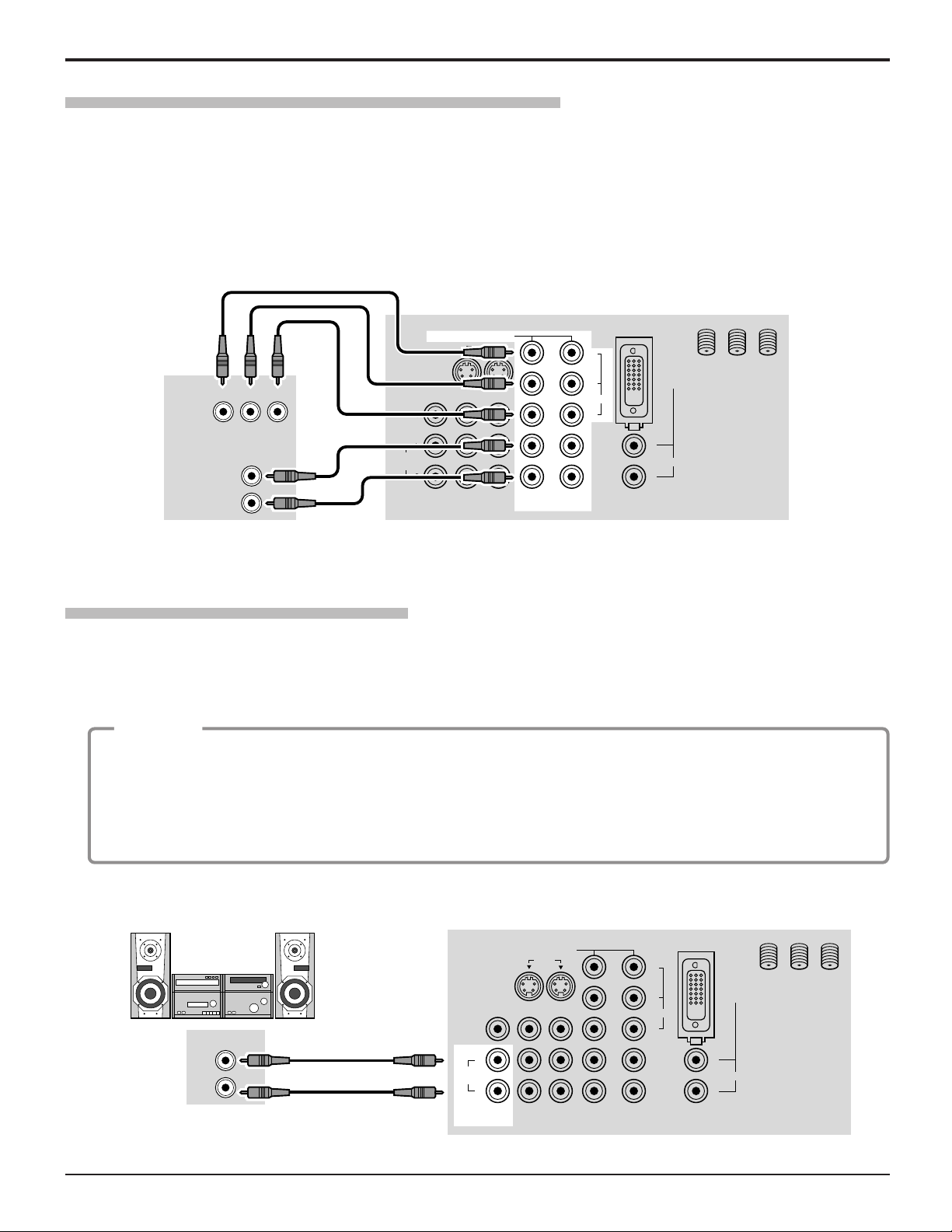
Amplifier Connection (TO AUDIO AMP)
To listen through a separate stereo system, connect an external audio amplifier TO AUDIO AMP outputs on back of
television.
Note: TO AUDIO AMP terminals cannot be connected directly to external speakers.
Select SPEAKERS OFF & FIXED AUDIO OUT to control audio functions through the external amplifier.
CABLES NOT SUPPLIED
DIGITAL TV OUTPUT
MAIN
VIDEO
AUDIO OUTPUT
P
B
P
R
Y
R
L
PROG OUT
COMPONENT VIDEO INPUT
S VIDEO
DIGITAL
IN
VIDEO
Y
P
B
L
R
L
R
ANT 1 ANT 2
PR
12
12
INPUT
VIDEO
TO AUDIO
AMP
AUDIO
SPLIT
OUT
DTV INPUT TERMINALS ON BACK OF TV
CABLES NOT SUPPLIED
CONNECTIONS ON BACK OF TV
External Amplifier
Procedure
1. Select SPEAKERS ON located in the onscreen AUDIO menu.
2. Set amplifier volume to minimum.
3. Adjust television volume to desired level.
4. Adjust amplifier volume to match the television.
5. Select SPEAKERS OFF & VARIABLE AUDIO OUT from AUDIO menu.
6. Volume, mute, bass, treble and balance are now controlled through the television.
Audio Adjustments
16
PROG OUT
COMPONENT VIDEO INPUT
S VIDEO
DIGITAL
IN
VIDEO
Y
P
B
L
R
L
R
ANT 1 ANT 2
P
R
12
12
INPUT
VIDEO
TO AUDIO
AMP
AUDIO
SPLIT
OUT

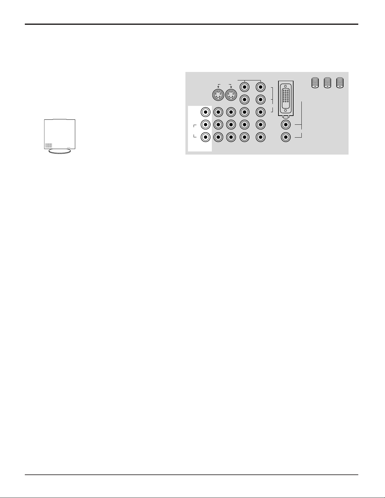
17
PC Input Terminals connection
Notes:
(1) Computer signals which can be input are those with a horizontal scanning frequency of 15 to 110 kHz and vertical
scanning frequency of 48 to 120 Hz. (However, the image will not be displayed properly if the signals exceed 1,200 lines.)
(2) The display resolution is a maximum of 640 × 480 dots when the aspect mode is set to “4:3”, and 852 × 480 dots
when the aspect mode is set to “16:9”. If the display resolution exceeds these maximums, it may not be possible to
show fine detail with sufficient clarity.
(3) Some PC models cannot be connected to the set.
(4) There is no need to use an adapter for computers with DOS/V compatible D-sub 15P terminal.
(5) The computer shown in the illustration is for example purposes only.
(6) Additional equipment and cables shown are not supplied with this set.
(7) Do not set the horizontal and vertical scanning frequencies for PC signals which are above or below the specified
frequency range.
18
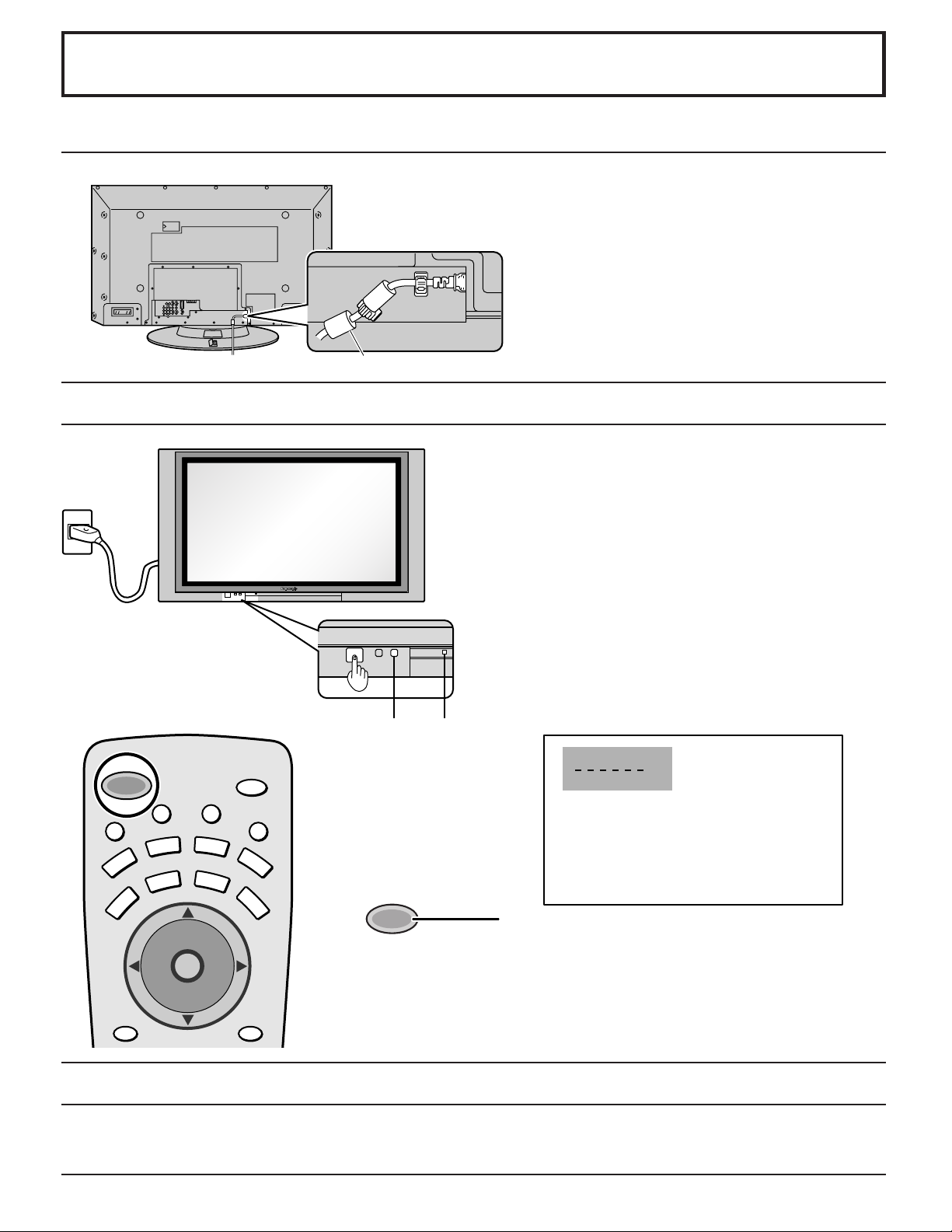
Power ON / OFF
AC cord connection
Connecting the Plug to the Wall Outlet
Note:
The TV’s power cord must first be plugged into the wall
outlet and then turned on at the POWER switch (standby
mode).
Press the POWER switch on the TV to turn the set on.
POWER-ON: Red
When the set is on press the POWER switch on the TV
to turn the set off.
STANDBY: No light
Example: The screen below is displayed for a while after
the TV is turned on. (setting condition is an
example.)
Press the POWER button on the remote control to turn
the TV on: Red
Press the POWER button on the remote control to turn
the TV off: No light (standby)
How to Turn the Power On
POWER
Remote
Control
senser
Power
indicater
CH 3
SAP
JUST
VIVID
A
C
T
I
O
N
TV
DTV
CBL
AUX
DVD
VCR
DBS
RCVR
CH
CH
VOL VOL
RECALL
SAP
PC
MENU
M
U
T
E
A
S
P
E
C
T
T
V
/
V
I
D
E
O
L
I
G
H
T
POWER
POWER
Menu Language Selection
In SET UP Menu, Select IDIOMA/LANGUE to change menu language to ENGLISH, ESPAÑOL (Spanish) or FRANÇAIS
(French). (refer to page 24)
Note:
The TV will still consume some power as long as the power cord is still inserted
into the wall outlet.
Connecting the AC cord plug to the Plasma TV.
Ferrite core (large size) (supplied)
Fix the AC cord plug securely to the
Plasma TV with the clamper.
19
INPUT
OUTPUT
S-VIDEO
PC
CHANNELVOLUMEACTIONINPUT
HPJ
VIDEO
VIDEO
3
R AUDIO L
POWER
S VIDEO
PC
CHANNELVOLUMEACTION INPUT
HPJ
VIDEO
INPUT
3
L AUDIO R
Cable TV / VHF, UHF and CATV
Press to turn the TV on (See page 18).
Press
TV
to operate the TV set with the
remote control.
Press to select the desired channel.
Select the desired volume level.
Notes:
(1) The channel number and volume level remain the same
even after the TV is turned off.
(2) Power consumption and howling sound can be reduced if
the volume level is lowered.
1
2
3
4
Power switch
Remote control sensor
Operation can be done
from the TV set.
•
Channel selectors
•
Volume adjusters
TV
POWER
A
C
T
I
O
N
CH
CH
VOL VOL
A
C
T
I
O
N
CH
CH
VOL VOL
DTV
AUX
DVD
VCR
DBS
RCVR
RECALL
PC
MENU
SAP
M
U
T
E
A
S
P
E
C
T
T
V
/
V
I
D
E
O
L
I
G
H
T
POWER
CBL
CH
CH
VOL VOL
A
C
T
I
O
N
TV
ACTION button
(Press to make
selections.)
INPUT button
(Change to input
signal.)
C.A.T.S sensor
Plasma C.A.T.S (Contrast Automatic Tracking System)
Plasma C.A.T.S automatically senses the ambient light conditions and
adjusts the brightness and gradation accordingly, to optimise contrast.
(Effective when Picture mode is set to Auto.)
Cable TV
When the antenna cable is connected to the TV antenna
terminal via a cable box or VCR, set the TV channel to
CH3 or CH4.
This does not apply when signal is input from VIDEO
INPUT.
Confirming
Confirm that registration with cable TV provider and
connection of equipment are completed. Turn the CABLE
BOX on and select the desired volume level.
Press while pointing the remote control
towards the CABLE BOX.
Note:
The remote control code number is set
for Panasonic products.
When peripheral equipment does not
operate, reset code (See page 54 - 55).
Operate the CABLE BOX and select the desired
volume level.
1
2
3
Press
CBL
to confirm.
POWER
CBL
VHF, UHF and CATV
ANTENNA TERMINAL ON
THE BACK OF THE TV
CABLE BOX
To Antenna
Input
Incoming Cable
from Antenna or
Cable TV System.
Ferrite core (large size)
(supplied)
Less than
4” (10 cm)
20
Illuminated Remote Control
Location of Controls
Power button
Press to turn the TV ON or OFF (See page 18).
Note: The TV’s power cord must first be plugged into the wall outlet
and then turned on at the POWER switch (standby mode).
R-TUNE button
Switches to previously viewed channel or video mode.
MUTE button
Press this button to mute the sound, press again to cancel the mute.
Operation of other Device
TV
DTV
CBL
AUX
DVD
VCR
DBS
RCVR
Mode Selection buttons
Selects the operation mode for the remote control. (See page 55)
VCR Mode Selection for Remote Control
Digital Video Disk Mode Selection for Remote Control
Aux Mode Selection for Remote Control
TV Mode Selection for Remote Control
Digital Broadcasting Satellite for
Remote Control
Receiver/Amplifier Mode Selection
for Remote Control
Digital TV Mode Selection for Remote Control
Cable TV Mode Selection for Remote Control
PIP or SPLIT FREEZE
TV/VCR Switch
TV/DBS Switch
-
-
PIP or SPLIT CH up/down
VCR CH up/down
TV/DBS CH up/down
-
-
PIP Search
-
-
OPEN/CLOSE
-
TV
VCR
CABLE/DBS
DVD/LD/CD
RCVR
TV
VCR
CABLE/DBS
DVD/LD/CD
RCVR
PIP Minimize/Maximize
VCR REW/FF
-
Skip Search REW/FF
Surround
-
/+
-
PLAY
-
PLAY
-
-
VCR RECORD
DBS RECORD
-
-
-
Pause
-
Pause
-
-
STOP
-
STOP
-
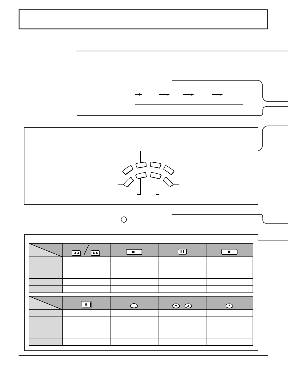
ButtonsButtons
Device
PIP MAX
FF
STOP
PIP MIN
REW
PLAY
PAUSE
ButtonsButtons
Device
SEARCH
OPEN/CLOSE
REC
FREEZE
TV/VCR
PIP CH
VCR CH
ASPECT button
Change of screen size (See page 50).
R-TUNE
ZOOM FULL
JUST 4 : 3
 Loading...