


Panasonic U-96MF1U9E, U-72MF1U9, U-52LE1U6, U-36LE1U6, S-54MF1U6 Installation Instructions
...INSTALLATION INSTRUCTIONS
VRF System Air Conditioner
This air conditioner uses the refrigerant R410A.
NOTE External diameter of service port R410A: 5/16"
Model No.
Indoor Units |
|
|
|
|
|
|
|
|
|
|
|
|
|
|
|
|
|
|
|
|
|
|
|
Type |
Indoor Unit Type |
7 |
9 |
12 |
15 |
18 |
19 |
24 |
36 |
48 |
54 |
|
|
|
|
|
|
|
|
|
|
|
|
U1 |
4-Way Cassette |
|
|
S-12MU1U6 |
|
S-18MU1U6 |
|
S-24MU1U6 |
S-36MU1U6 |
|
|
|
|
(CZ-36KPU2U)** |
|
(CZ-36KPU2U)** |
|
(CZ-36KPU2U)** |
(CZ-36KPU2U)** |
|
|
||
|
|
|
|
|
|
|
|
||||
Y1 |
4-Way Cassette |
|
|
S-12MY1U6 |
|
S-18MY1U6 |
|
|
|
|
|
60 × 60 |
|
|
(CZ-18KPY1U)** |
|
(CZ-18KPY1U)** |
|
|
|
|
|
|
|
|
|
|
|
|
|
|
|
|||
D1 |
1-Way Cassette |
S-07MD1U6 |
S-09MD1U6 |
S-12MD1U6 |
|
|
|
|
|
|
|
(CZ-12KPD1U)** |
(CZ-12KPD1U)** |
(CZ-12KPD1U)** |
|
|
|
|
|
|
|
||
|
|
|
|
|
|
|
|
|
|||
F1 |
Low Silhouette |
S-07MF1U6 |
S-09MF1U6 |
S-12MF1U6 |
S-15MF1U6 |
S-18MF1U6 |
|
S-24MF1U6 |
S-36MF1U6 |
S-48MF1U6 |
S-54MF1U6 |
Ducted |
|
||||||||||
|
|
|
|
|
|
|
|
|
|
|
|
M1 |
Slim Low Static |
S-07MM1U6 |
S-09MM1U6 |
S-12MM1U6 |
S-15MM1U6 |
S-18MM1U6 |
|
|
|
|
|
Ducted |
|
|
|
|
|
||||||
|
|
|
|
|
|
|
|
|
|
|
|
E1 |
High Static |
|
|
|
|
|
|
|
S-36ME1U6 |
S-48ME1U6 |
|
Pressure Ducted |
|
|
|
|
|
|
|
|
|||
|
|
|
|
|
|
|
|
|
|
|
|
T1 |
Ceiling |
|
|
S-12MT1U6 |
|
S-18MT1U6 |
|
S-24MT1U6 |
|
|
|
|
|
|
|
|
|
|
|
|
|
|
|
K1 |
Wall Mounted |
S-07MK1U6 |
S-09MK1U6 |
S-12MK1U6 |
|
S-18MK1U6 |
S-19MS1U6* |
S-24MK1U6 |
|
|
|
|
|
|
|
|
|
|
|
|
|
|
|
P1 |
Floor Standing |
S-07MP1U6 |
S-09MP1U6 |
S-12MP1U6 |
S-15MP1U6 |
S-18MP1U6 |
|
S-24MP1U6 |
|
|
|
|
|
|
|
|
|
|
|
|
|
|
|
R1 |
Concealed Floor |
S-07MR1U6 |
S-09MR1U6 |
S-12MR1U6 |
S-15MR1U6 |
S-18MR1U6 |
|
S-24MR1U6 |
|
|
|
Standing |
|
|
|
|
|||||||
|
|
|
|
|
|
|
|
|
|
|
|
*Necessary to install the External Electronic Expansion Valve Kit (Optional : CZ-P56SVK1U)
**Panel (optional parts)
Optional Controllers
|
Timer Remote Controller |
CZ-RTC2 |
|
Wireless Remote Controller (For F1, M1, E1, P1, R1 Types) |
CZ-RWSC1U |
|
Wireless Remote Controller (For U1 Type) |
CZ-RWSU1U |
|
Wireless Remote Controller (For Y1 Type) |
CZ-RWSY1U |
|
Wireless Remote Controller (For D1, T1 Types) |
CZ-RWST1U |
|
Wireless Remote Controller (For K1 Type) |
CZ-RWSK1U |
RC |
Simplifi ed Remote Controller |
CZ-RE2C2 |
|
System Controller |
CZ-64ESMC1U |
|
Schedule Timer |
CZ-ESWC2 |
|
Intelligent Controller |
CZ-256ESMC1U |
|
Communication Adaptor |
CZ-CFUNC1U |
|
Remote Sensor |
CZ-CSRC2 |
|
LonWorks Interface |
CZ-CLNC1U |
85464369530011 |
CV6233187013 |
|
|
|
|
|
|
|
|
|
|
|
|
|
|
VRF_Indoor_US.indb 1 |
|
2011/09/30 12:22:53 |
|
|
|
|
|
|
|
||||
|
|
|
|
|
|
|
IMPORTANT!
Please Read Before Starting
This air conditioning system meets strict safety and operating standards. As the installer or service person, it is an important part of your job to install or service the system so it operates safely and effi ciently.
For safe installation and trouble-free operation, you must:
●Carefully read this instruction booklet before beginning.
●Follow each installation or repair step exactly as shown.
●Observe all local, state, and national electrical codes.
●Pay close attention to all warning and caution notices given in this manual.
This symbol refers to a hazard or WARNING unsafe practice which can result in severe personal injury or death.
This symbol refers to a hazard or
CAUTION unsafe practice which can result in personal injury or product or
property damage.
If Necessary, Get Help
These instructions are all you need for most installation sites and maintenance conditions. If you require help for a special problem, contact our sales/service outlet or your certifi ed dealer for additional instructions.
In Case of Improper Installation
The manufacturer shall in no way be responsible for improper installation or maintenance service, including failure to follow the instructions in this document.
SPECIAL PRECAUTIONS
WARNING When Wiring
ELECTRICAL SHOCK CAN CAUSE
SEVERE PERSONAL INJURY OR DEATH.
ONLY A QUALIFIED, EXPERIENCED
ELECTRICIAN SHOULD ATTEMPT TO
WIRE THIS SYSTEM.
•Do not supply power to the unit until all wiring and tubing are completed or reconnected and checked.
•Highly dangerous electrical voltages are used in this system. Carefully refer to the wiring diagram and these instructions when wiring. Improper connections and inadequate grounding can cause accidental injury or death.
•Ground the unit following local electrical codes.
•Connect all wiring tightly. Loose wiring may cause overheating at connection points and a possible fi re hazard.
• To prevent possible hazards from insulation failure, the unit must be grounded.
When Transporting
Be careful when picking up and moving the indoor and outdoor units. Get a partner to help, and bend your knees when lifting to reduce strain on your back. Sharp edges or
thin aluminum fi ns on the air conditioner can cut your fi ngers.
When Installing…
Select an installation location which is rigid and strong enough to support or hold the unit, and select a location for easy maintenance.
…In a Room
Properly insulate any tubing run inside a room to prevent “sweating” that can cause dripping and water damage to walls and fl oors.
Keep the fi re alarm and the air
CAUTION outlet at least 5 feet away from the unit.
…In Moist or Uneven Locations
Use a raised concrete pad or concrete blocks to provide a solid, level foundation for the outdoor unit. This prevents water damage and abnormal vibration.
…In an Area with High Winds
Securely anchor the outdoor unit down with bolts and a metal frame. Provide a suitable air baffl e.
…In a Snowy Area (for Heat Pump-type Systems)
Install the outdoor unit on a raised platform that is higher than drifting snow. Provide snow vents.
When Connecting Refrigerant Tubing
•Ventilate the room well, in the event that is refrigerant gas leaks during the installation. Be careful not to allow contact of the refrigerant gas with a fl ame as this will cause the generation of poisonous gas.
•Keep all tubing runs as short as possible.
•Use the fl are method for connecting tubing.
•Apply refrigerant lubricant to the matching surfaces of the fl are and union tubes before connecting them, then tighten the nut with a torque wrench for a leak-free connection.
•Check carefully for leaks before starting the test run.
•When performing piping work do not mix air except for specifIed refrigerant (R410A) in refrigeration cycle. It causes capacity down, and risk of explosion and injury due to high tension inside the refrigerant
WARNING cycle.
•Refrigerant gas leakage may cause fi re.
•Do not add or replace refrigerant other than specifi ed type. It may cause product damage, burst and injury etc.
•Do not leak refrigerant while piping work for an installation or re-installation, and while repairing refrigeration parts.
Handle liquid refrigerant carefully as it may cause frostbite.
2
|
|
|
|
|
|
|
|
|
|
|
|
|
|
VRF_Indoor_US.indb 2 |
|
2011/09/30 12:22:54 |
|
|
|
|
|
|
|
||||
|
|
|
|
|
|
|
When Servicing
•Turn the power OFF at the main power box (mains) before opening the unit to check or repair electrical parts and wiring.
•Keep your fi ngers and clothing away from any moving parts.
•Clean up the site after you fi nish, remembering to check that no metal scraps or bits of wiring have been left inside the unit being serviced.
• Do not clean inside the indoor and WARNING outdoor units by users. Engage
authorized dealer or specialist for cleaning.
•In case of malfunction of this appliance, do not repair by yourself. Contact to the sales dealer or service dealer for a repair.
• Do not touch the air inlet or the CAUTION sharp aluminum fi ns of the
outdoor unit. You may get injured.
•Ventilate any enclosed areas when installing or testing the refrigeration system. Escaped refrigerant gas, on contact with fi re or heat, can produce dangerously toxic gas.
•Confi rm after installation that no refrigerant gas is leaking. If the gas comes in contact with a burning stove, gas water heater, electric room heater or other heat source, it can cause the generation of poisonous gas.
Others
CAUTION
• Do not touch the air inlet or the  sharp aluminum fi ns of the
 outdoor unit. You may get injured.
• Do not sit or step on the unit, you may fall down accidentally.
• Do not stick any object into the FAN CASE. You may be injured and the unit
may be damaged.
Check of Density Limit
The room in which the air conditioner is to be installed requires a design that in the event of refrigerant gas leaking out, its density will not exceed a set limit.
The refrigerant (R410A), which is used in the air conditioner, is safe, without the toxicity or combustibility of ammonia, and is not restricted by laws imposed to protect the ozone layer. However, since it contains more than air, it poses the risk of suffocation if its density should rise excessively. Suffocation from leakage of refrigerant is almost non-existent. With the recent increase in the number of high density buildings, however, the installation of multi air conditioner systems is on the increase because of the need for effective use of fl oor space, individual control, energy conservation by curtailing heat and carrying power, etc.
Most importantly, the multi air conditioner system is able to replenish a large amount of refrigerant compared to conventional individual air conditioners. If a single unit of the multi air conditioner system is to be installed in a small room, select a suitable model and installation procedure so that if the refrigerant accidentally leaks out, its density does not reach the limit (and in the event of an emergency, measures can be made before injury can occur).
ASHRAE and the International Mechanical Code of the ICC as well as CSA provide guidance and defi ne safeguards related to the use of refrigerants, all of which defi ne a Refrigerant Concentration Level (RCL) of
25 pounds per 1,000 cubic feet for R410A refrigerant. For additional guidance and precautions related to refrigerant safety, please refer to the following documents:
International Mechanical Code 2009 (IMC-2009) (or more recently revised)
ASHRAE 15
ASHRAE 34
3
|
|
|
|
|
|
|
|
|
|
|
|
|
|
VRF_Indoor_US.indb 3 |
|
2011/09/30 12:22:54 |
|
|
|
|
|
|
|
||||
|
|
|
|
|
|
|
CONTENTS
|
Page |
IMPORTANT! |
.................................................................2 |
Please Read Before Starting
Check of Density Limit
1.GENERAL...................................................................5
1-1. Tools Required for Installation (not supplied)
1-2. Accessories Supplied
1-3. Type of Copper Tube and Insulation Material 1-4. Additional Materials Required for Installation
2.SELECTING THE INSTALLATION SITE ...................9
2-1. Indoor Unit
3.HOW TO INSTALL THE INDOOR UNIT...................10
■ 4-Way Cassette Type (U1 Type)
3-1. Preparation for Suspending
3-2. Suspending the Indoor Unit
3-3. Placing the Unit Inside the Ceiling
3-4. Installing the Drain Piping
3-5. Checking the Drainage
3-6. How to Install the Ceiling Panel
3-7. Special Remarks
■4-Way Cassette 60 × 60 Type (Y1 Type)
3-8. Preparation for Suspending
3-9. Suspending the Indoor Unit
3-10. Placing the Unit Inside the Ceiling
3-11. Installing the Drain Piping
3-12. Checking the Drainage
3-13. How to Install the Ceiling Panel
■1-Way Cassette Type (D1 Type)
3-14. Suspending the Indoor Unit
3-15. Placing the Unit Inside the Ceiling
3-16. Installing the Drain Piping
3-17. Checking the Drainage
3-18. Electrical Power Wiring
3-19. How to Install the Ceiling Panel
■Low Silhouette Ducted Type (F1 Type)
3-20. Required Minimum Space for Installation and Service 3-21. Suspending the Indoor Unit
3-22. Installing the Drain Piping
3-23. Checking the Drainage
3-24. Increasing the Fan Speed
3-25. When Installing the Indoor Unit
3-26. Required Minimum Space for Installation and Service
■Slim Low Static Ducted Type (M1 Type)
3-27. Required Minimum Space for Installation and Service 3-28. Preparations Before Installation
3-29. For Bottom Intake
3-30. Installing the Duct
3-31. Suspending the Indoor Unit
3-32. Installing the Drain Piping
3-33. Checking the Drainage
3-34. Increasing the Fan Speed
■High Static Pressure Ducted Type (E1 Type)
3-35. Required Minimum Space for Installation and Service 3-36. Suspending the Indoor Unit
3-37. Installing the Drain Piping
3-38. Caution for Ducting Work
3-39. Indoor Fan Performance
Page
■Ceiling Type (T1 Type)
3-40. Required Minimum Space for Installation and Service 3-41. Suspending the Indoor Unit
3-42. Duct for Fresh Air
3-43. Shaping the Tubing
3-44. Installing the Drain Piping
■Wall Mounted Type (K1 Type)
3-45. Removing the Rear Panel from the Unit 3-46. Selecting and Making a Hole
3-47. Installing the Rear Panel onto the Wall 3-48. Removing the Grille to Install the Indoor Unit 3-49. Preparing the Tubing
3-50. Shaping the Tubing
3-51. Installing the Drain Hose
3-52. When Using Wireless Remote Controller Instead of Wired Remote Controller
3-53. External Electronic Expansion Valve Kit (CZ-P56SVK1U)
■Floor Standing Type (P1 Type) Concealed Floor Standing Type (R1 Type)
3-54. Required Minimum Space for Installation and Service 3-55. Dimensions and Part Names
3-56. Removing and Attaching the Front Panel (Floor Standing Type)
3-57. Installing the Refrigerant Tubing
3-58. Installing the Drain Piping
3-59. Installing the Remote Controller
■SUPPLEMENT ON DRAIN PIPING
4. ELECTRICAL WIRING ............................................ |
63 |
|
4-1. General Precautions on Wiring |
|
|
4-2. |
Recommended Wire Length and Wire Diameter for |
|
|
Power Supply System |
|
4-3. |
Wiring System Diagram |
|
4-4. |
Important Note When Wiring for Common Type |
|
4-5. |
Important Note When Wiring for Y1 Type |
|
5. HOW TO PROCESS TUBING .................................. |
71 |
|
5-1. Connecting the Refrigerant Tubing |
|
|
5-2. |
Connecting Tubing Between Indoor and Outdoor Units |
|
5-3. |
Insulating the Refrigerant Tubing |
|
5-4. |
Taping the Tubes |
|
5-5. |
Finishing the Installation |
|
6. APPENDIX ................................................................ |
75 |
|
■NAME OF PARTS
■Care and Cleaning
■Troubleshooting
■Tips for Energy Saving
4
|
|
|
|
|
|
|
|
|
|
|
|
|
|
VRF_Indoor_US.indb 4 |
|
2011/09/30 12:22:54 |
|
|
|
|
|
|
|
||||
|
|
|
|
|
|
|
1. GENERAL
This booklet briefl y outlines where and how to install the air conditioning system. Please read over the entire set of instructions for the outdoor unit and make sure all accessory parts listed are with the system before beginning.
1-1. Tools Required for Installation (not supplied)
1.Flathead screwdriver
2.Phillips head screwdriver
3.Knife or wire stripper
4.Tape measure
5.Level gauge
6.Sabre saw or key hole saw
7.Hacksaw
8.Core bits
9.Hammer
10.Drill
11.Tube cutter
12.Tube flaring tool
13.Torque wrench
14.Adjustable wrench
15.Reamer (for deburring)
1-2. Accessories Supplied
See Tables 1-1 – 1-9.
1-3. Type of Copper Tube and Insulation Material
If you wish to purchase these materials separately from a local source, you will need:
1.Deoxidized annealed copper tube for refrigerant tubing.
2.Foamed polyethylene insulation for copper tubes as required to precise length of tubing. Wall thickness of the insulation should be not less than 5/16 in.
3.Use insulated copper wire for field wiring. Wire size varies with the total length of wiring.
Refer to “4. ELECTRICAL WIRING” for details.
Check local electrical codes and
regulations before obtaining wire.
CAUTION
Also, check any specified
instructions or limitations.
1-4. Additional Materials Required for Installation
1.Refrigeration (armored) tape
2.Insulated staples or clamps for connecting wire (See your local codes.)
3.Putty
4.Refrigeration tubing lubricant
5.Clamps or saddles to secure refrigerant tubing
6.Scale for weighing
5
|
|
|
|
|
|
|
|
|
|
|
|
|
|
VRF_Indoor_US.indb 5 |
|
2011/09/30 12:22:54 |
|
|
|
|
|
|
|
||||
|
|
|
|
|
|
|

Table 1-1 (4-Way Cassette) |
|
|
|
|
Part Name |
Figure |
Q’ty |
Remarks |
|
Full-scale installation diagram |
|
1 |
Printed on container box |
|
Drain hose |
|
1 |
For securing drain hose |
|
Hose band |
|
1 |
For securing drain hose |
|
Drain insulator |
|
1 |
For drain joint |
|
Flare insulator |
|
1 |
For liquid tube |
|
|
1 |
For gas tube |
||
|
|
|||
Insulating tape |
White |
2 |
For gas tube joint |
|
(heat-resisting) |
||||
|
|
|
||
Packing |
|
1 |
For drain joint |
|
Wiring cover |
|
1 |
For covering electrical wiring |
|
Screw |
|
4 |
For full-scale installation diagram |
|
Washer |
|
8 |
For suspending indoor unit from ceiling |
|
Screw |
|
1 |
For fi xing the wiring cover |
Table 1-2 (1-Way Cassette)
Part Name |
Figure |
Q’ty |
Remarks |
|
Full-scale installation diagram |
|
1 |
Printed on container box |
|
Drain hose |
|
1 |
For securing drain hose |
|
Hose band |
|
1 |
For securing drain hose |
|
Drain insulator |
|
1 |
For drain joint |
|
Flare insulator |
|
1 |
For liquid tube |
|
|
1 |
For gas tube |
||
|
|
|||
Insulating tape |
White |
2 |
For gas tube joint |
|
(heat-resisting) |
||||
|
|
|
||
Packing |
|
1 |
For drain joint |
|
Washer |
|
8 |
For suspending indoor unit from ceiling |
|
Screw |
|
4 |
For full-scale installation diagram |
|
Bushing |
|
1 |
For electrical junction box |
Table 1-3 (Low Silhouette Ducted)
Part Name |
Figure |
Q’ty |
Remarks |
|
Drain hose |
|
1 |
For securing drain hose |
|
Hose band |
|
1 |
For securing drain hose |
|
Packing |
|
1 |
For drain joint |
|
Drain insulator |
|
1 |
For drain joint |
|
Flare insulator |
|
1 |
For liquid tube |
|
Insulating tape |
White |
2 |
For gas and liquid tubes fl are nuts |
|
(heat-resisting) |
||||
|
|
|
||
Flare insulator |
|
1 |
For gas tube |
|
Washer |
|
8 |
For suspending indoor unit from ceiling |
|
Sealing putty |
|
1 |
For sealing recessed portion of power supply |
|
Vinyl clamp |
|
8 |
For fl are and drain insulators |
●Use M10 or 3/8" for suspending bolts.
●Field supply for suspending bolts and nuts.
6
|
|
|
|
|
|
|
|
|
|
|
|
|
|
VRF_Indoor_US.indb 6 |
|
2011/09/30 12:22:54 |
|
|
|
|
|
|
|
||||
|
|
|
|
|
|
|
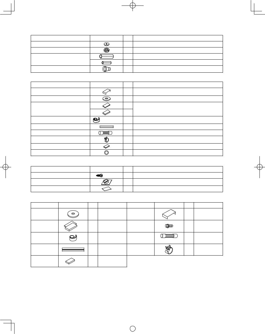
Table 1-4 (High Static Pressure Ducted)
Part Name |
Figure |
Q’ty |
Remarks |
Washer |
|
8 |
For suspending indoor unit from ceiling |
Nut |
|
8 |
For suspending indoor unit from ceiling |
Flare insulator |
|
1 |
For gas tube |
|
1 |
For liquid tube |
|
|
|
||
Drain socket |
|
1 |
For drain pipe connection |
Table 1-5 (Ceiling)
Part Name |
Figure |
Q’ty |
Remarks |
|
Full-scale installation diagram |
|
1 |
Printed on container box |
|
Washer |
|
4 |
For temporarily suspending indoor unit from ceiling |
|
|
T1/8" |
2 |
|
|
Flare insulator |
|
For gas and liquid tube joints |
||
|
2 |
|||
|
T3/16" |
|
||
|
|
|
||
Insulating tape |
White |
2 |
For gas and liquid tubes fl are nuts |
|
(heat-resisting) |
||||
|
|
|
||
Vinyl clamp |
|
8 |
For fl are and drain insulators |
|
Drain hose |
L5-1/2" |
1 |
For main unit and PVC pipe joints |
|
Hose band |
|
2 |
For drain hose connection |
|
Drain insulator |
|
1 |
For drain hose joint |
|
Gum eyelet |
|
2 |
For power supply inlet and 3 way wiring inlet |
Table 1-6 (Wall Mounted)
Part Name |
Figure |
Q’ty |
Remarks |
Tapping screw |
5/32" × 1" |
10 |
For fi xing the rear panel |
Plastic cover |
|
1 |
For improved tubing appearance |
Insulator |
|
1 |
For insulating fl are nut (1862, 1962, 2452) |
Table 1-7 (4-Way Cassette 60 × 60)
Part Name |
Figure |
Q’ty |
Remarks |
Part Name |
Figure |
Q’ty |
Remarks |
|
|
|
For temporarily |
Full-scale |
|
|
Printed on |
Washer |
|
8 |
suspending indoor |
installation |
|
1 |
|
|
|
container box |
|||||
|
|
|
unit from ceiling |
diagram |
|
|
|
|
|
|
|
|
|
||
|
T3 |
2 |
For gas / liquid |
Washer head |
|
|
For full-scale |
Flare insulation |
|
4 |
installation |
||||
T5 |
set |
tube connection |
screw |
|
|||
|
|
|
diagram |
||||
|
|
|
|
|
|
||
|
|
|
|
|
|
|
|
|
|
|
For gas / liquid |
|
|
|
For unit & PVC |
Insulation tie |
|
2 |
tube / fl are nut |
Drain hose |
|
1 |
|
|
L140 |
tube connection |
|||||
|
|
|
connection |
|
|
||
|
|
|
|
|
|
|
|
|
|
|
For fl are / drain |
|
|
|
For drain hose |
Vinyl tie |
|
8 |
insulating |
Hose band |
|
2 |
|
|
|
connection |
|||||
|
|
|
connection |
|
|
|
|
|
|
|
|
|
|
|
|
Drain hose |
|
1 |
For drain tube |
|
|
|
|
insulation |
T10 |
connection |
|
|
|
|
|
|
|
|
|
|
●Use M10 or 3/8" for suspending bolts.
●Field supply for suspending bolts and nuts.
7
|
|
|
|
|
|
|
|
|
|
|
|
|
|
VRF_Indoor_US.indb 7 |
|
2011/09/30 12:22:55 |
|
|
|
|
|
|
|
||||
|
|
|
|
|
|
|
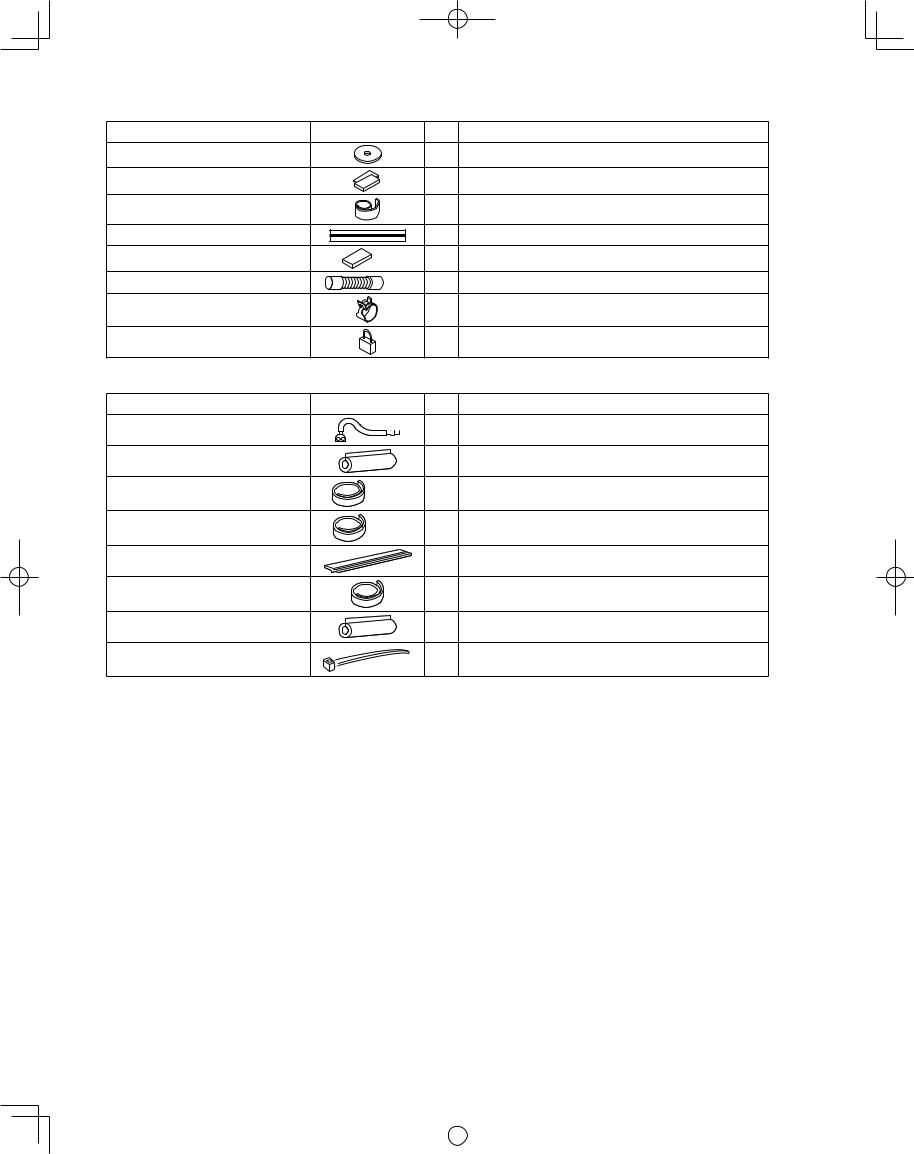
Table 1-8 (Slim Low Static Ducted)
Part Name |
Figure |
Q’ty |
Remarks |
|
Washer |
|
8 |
For suspension fi tting |
|
Flare insulation |
T3 |
2 set |
For gas / liquid tube connection |
|
T5 |
||||
|
|
|
||
Insulation tape |
|
2 |
For gas / liquid tube / fl are nut connection |
|
Vinyl tie |
|
8 |
For fl are / drain insulating connection |
|
Drain hose insulation |
T10 |
1 |
For drain tube connection |
|
Drain hose |
L140 |
1 |
For unit & PVC tube connection |
|
Hose band |
|
2 |
For drain hose connection |
|
Short circuit connection |
|
1 |
For high static pressure |
|
|
(Located on the back of the electrical component box lid.) |
|||
|
|
|
Table 1-9 (Floor Standing & Concealed Floor Standing)
Part Name |
Figure |
Q’ty |
Remarks |
Connection pipe |
|
1 |
For connecting gas tubes |
Flare insulator |
|
2 |
For gas and liquid tubes |
Insulating tape |
(White) |
2 |
For gas and liquid tube fl are nuts |
|
|
|
|
Insulating tape |
(Black) |
2 |
For gas and liquid tubes |
|
|
|
|
Vinyl clamp |
|
7 |
For ends of fl are insulator |
Insulating tape (black and long) |
|
1 |
For drain pipe |
Drain insulator |
|
1 |
For drain hose joint |
Binding strap |
|
2 |
|
●Use M10 or 3/8" for suspending bolts.
●Field supply for suspending bolts and nuts.
8
|
|
|
|
|
|
|
|
|
|
|
|
|
|
VRF_Indoor_US.indb 8 |
|
2011/09/30 12:22:55 |
|
|
|
|
|
|
|
||||
|
|
|
|
|
|
|
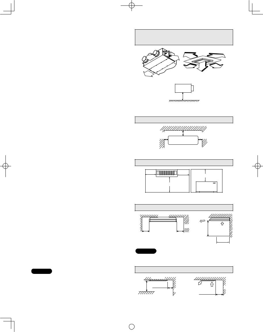
2. SELECTING THE INSTALLATION SITE
2-1. Indoor Unit
AVOID:
●areas where leakage of fl ammable gas may be expected.
●places where large amounts of oil mist exist.
●direct sunlight.
●locations near heat sources which may affect the performance of the unit.
●locations where external air may enter the room directly. This may cause “sweating” on the air discharge ports, causing them to spray or drip.
●locations where the remote controller will be splashed with water or affected by dampness or humidity.
●installing the remote controller behind curtains or furniture.
●locations where high-frequency emissions are generated.
DO:
●select an appropriate position from which every corner of the room can be uniformly cooled.
●select a location where the ceiling is strong enough to support the weight of the unit.
●select a location where tubing and drain pipe have the shortest run to the outdoor unit.
●allow room for operation and maintenance as well as unrestricted air fl ow around the unit.
●install the unit within the maximum elevation difference above or below the outdoor unit and within a total tubing length (L) from the outdoor unit as detailed in the installation manual packed with the outdoor unit.
●allow room for mounting the remote controller about 3 ft. off the fl oor, in an area that is not in direct sunlight nor in the
fl ow of cool air from the indoor unit.
●The elevation (Low Silhouette Ducted, Slim Low Static Ducted) between the bottom unit and the fl oor surface should be at least 8 feet.
●If the elevation (Low Silhouette Ducted, Slim Low Static Ducted) between them is less than 8 feet, install a fi lter (optional/fi eld supply) or a protective device (fi eld supply) not to touch the electrical parts or fan with hands.
●The air intake and outtake openings should be provided with the same location of a room.
Slim Low Static Ducted Type
Low Silhouette Ducted (High Static Pressure) Type 4-Way Cassette (60 × 60) Type
10 in. |
3 ft. |
|
3 ft. |
10 in. |
|
|
|
|
3 ft. |
3 ft. |
3 ft. |
10 in.
Fig. 2-1
Min.8 ft.
Shows Low Silhouette Ducted Type
and Slim Low Static Ducted Type
Fig. 2-2
Wall Mounted Type
Min. |
Min. 6 in. |
Min. |
6 in. |
|
6 in. |
Front View
Fig. 2-3
Floor Standing, Concealed Floor Standing Type
min. |
min. |
3-15/16" |
3-15/16" |
|
min. 3.3 ft. |
|
min. 3.3 ft. |
Horizontal view |
Vertical view |
Fig. 2-4
Ceiling Type
Ceiling |
Wall |
Min. 10 in. |
Min. 10 in. |
Front view
NOTE
Air |
|
discharge |
|
Min. 2 ft. |
Air intake |
|
Side view
Max. 10 in.
Obstacle
The rear of the indoor unit can be installed fl ush against the wall.
Fig. 2-5
NOTE
Air delivery will be degraded if the distance from the fl oor to the ceiling is greater than 10 ft.
|
1-Way Cassette Type |
|
||
|
Ceiling |
|
|
|
3 ft. |
Air |
|
|
|
discharge |
Air |
|
||
Min. |
Min. 2 in. |
intake |
Wall |
|
Wall |
||||
|
||||
|
Min. 2 in. |
|
||
Obstacle |
|
|
||
|
|
|
||
Side view
9 |
Fig. 2-6 |
|
|
|
|
|
|
|
|
|
|
|
|
|
|
|
VRF_Indoor_US.indb 9 |
|
2011/09/30 12:22:55 |
|
|
|
|
|
|
|
||||
|
|
|
|
|
|
|
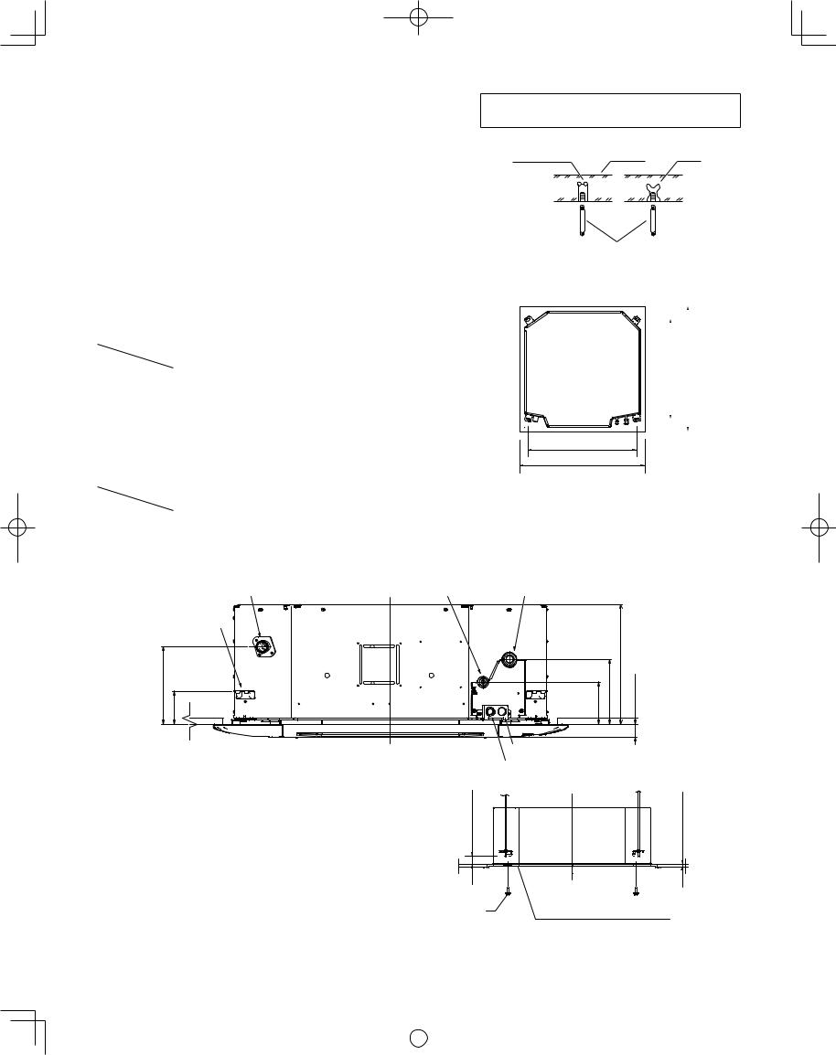
3. HOW TO INSTALL THE INDOOR UNIT
■ 4-Way Cassette Type (U1 Type)
3-1. Preparation for Suspending
This unit uses a drain pump. Use a level gauge to check that the unit is level.
3-2. Suspending the Indoor Unit
(1)Fix the suspension bolts securely in the ceiling using the method shown in the diagrams (Figs. 3-1 and 3-2), by attaching them to the ceiling support structure, or by any other method that ensures that the unit will be securely and safely suspended.
Note: For DC Fan Tap Change Procedure for 4-Way Cassette, see page 16.
Hole-in-anchor |
|
|
Hole-in-plug |
Concrete |
Insert |
Suspension bolt (M10 or 3/8") (field supply)
Fig. 3-1
(2) Follow Fig. 3-2 and Table 3-1 to make the holes in the ceiling.
Table 3-1 |
|
|
|
Unit: in. (mm) |
|
Length |
A |
B |
C |
|
D |
Type |
|
||||
|
|
|
|
|
|
|
|
|
|
|
|
12, 18, 24, 36 |
31-1/32 |
28-15/32 |
34-27/32 |
|
34-27/32 |
(788) |
(723) |
(885) |
|
(885) |
|
|
|
||||
(3)Determine the pitch of the suspension bolts using the supplied fullscale installation diagram. The diagram and table (Fig. 3-3 and Table 3-2) show the relationship between the positions of the suspension fi tting, unit, and panel.
Table 3-2 |
|
|
|
Unit: in. (mm) |
||
Length |
A |
B |
C |
D |
E |
|
Type |
|
|||||
|
|
|
|
|
|
|
|
|
|
|
|
|
|
12, 18, 24 |
4-29/64 |
6-13/16 |
10-5/64 |
8-17/64 |
3-15/32 |
|
(113) |
(173) |
(256) |
(210) |
(88) |
|
|
|
|
|||||
36 |
4-29/64 |
6-13/16 |
12-9/16 |
8-17/64 |
3-15/32 |
|
(113) |
(173) |
(319) |
(210) |
(88) |
|
|
|
|
|||||
|
Drain outlet(other side) |
Refrigerant tubing joint(liquid side) |
||||
|
|
(VP25) |
|
|||
|
|
|
|
|
|
|
|
|
(ceiling opening dimension) |
||
|
B (suspension bolt pitch) |
|
|
||
|
|
|
|
D |
|
|
|
|
|
||
|
|
|
|
|
|
A (suspension bolt pitch) |
C (ceiling opening dimension) |
Fig. 3-2
Refrigerant tubing joint(gas side)
Suspension lug |
|
|
|
|
|
|
C |
D E |
A |
B |
1-3/8 (35) |
|
Power supply outlet |
|
Unit: in. (mm) |
|
Inter-unit control wiring |
||
|
Fig. 3-3 |
|
|
3-3. Placing the Unit Inside the Ceiling |
(15)19/32Over |
43/64–15/32 |
17)–(12 |
|
|
|
|
||
(1) When placing the unit inside the ceiling, determine the |
|
|
|
|
pitch of the suspension bolts using the supplied full- |
|
|
|
|
scale installation diagram. (Fig. 3-4) |
|
|
|
|
Tubing and wiring must be laid inside the ceiling when |
|
|
|
|
suspending the unit. If the ceiling is already |
|
|
|
|
constructed, lay the tubing and wiring into position for |
|
Full-scale installation diagram |
Unit: in. (mm) |
|
connection to the unit before placing the unit inside |
Supplied bolt |
|||
(printed on top of container box) |
|
|||
the ceiling. |
|
Fig. 3-4 |
|
|
|
|
|
||
|
10 |
|
|
|
|
|
|
|
|
|
|
|
|
|
|
|
|
VRF_Indoor_US.indb 10 |
|
2011/09/30 12:22:56 |
|
|
|
|
|
|
|
||||
|
|
|
|
|
|
|
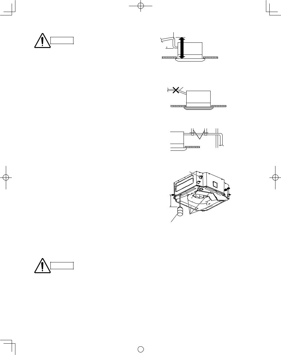
(2)The length of suspension bolts must be appropriate for a distance between the bottom of the bolt and the bottom of the unit of more than 19/32" as shown in Fig. 3-5.
(3)Thread the 3 hexagonal nuts and 2 washers (fi eld supply) onto each of the 4 suspension bolts as shown in Fig. 3-5. Use 1 nut and 1 washer for the upper side, and 2 nuts and 1 washer for the lower side, so that the unit will not fall off the suspension lugs.
(4)Adjust so that the distance between the unit and the ceiling bottom is 15/32" to 43/64". Tighten the nuts on the upper side and lower side of the suspension lug.
(5)Remove the protective polyethylene used to protect the fan parts during transport.
3-4. Installing the Drain Piping
(1)Prepare a standard hard PVC pipe (O.D. 1-1/4") for the drain and use the supplied drain hose and hose band to prevent water leaks.
The PVC pipe must be purchased separately. The unit’s transparent drain port allows you to check drainage. (Fig. 3-6)
CAUTION
●Insert the drain pipe until it contacts the socket, as shown in Fig. 3-6, then secure it tightly with the hose band.
●Do not use adhesive when connecting the supplied hose.
Reasons: 1. It may cause water to leak from the connection. Since the connection is slippery just after the adhesive has been applied, the pipe easily slips off.
2.The pipe cannot be removed when maintenance is needed.
●Do not bend the supplied drain hose 90° or more. The hose may slip off.
●Align the hose bands with the end of the hose. Tighten the hose band firmly. Please make sure that the bead is not covered by the hose band.
(Fig. 3-6)
Tighten the hose clamps so CAUTION their locking nuts face upward.
(Fig. 3-6)
(2)After checking the drainage, wrap the supplied packing and drain pipe insulator around the pipe. (Fig. 3-7)
NOTE
Make sure the drain pipe has a downward gradient (1/100 or more) and that there are no water traps.
11
|
|
|
|
|
|
|
|
|
Suspension bolt |
|||||||||
|
|
|
|
|
|
|
|
|
|
|
|
|
|
|
|
|
|
|
Nuts and washers |
|
|
|
|
|
|
|
|
Suspension lug |
|||||||||
(use for upper and lower) |
|
|
|
|
|
|
|
|
|
|
|
|
|
|
|
|
|
|
|
|
|
|
|
|
|
|
|
|
|
|
|
|
|
|
|
||
|
|
|
|
|
|
|
|
|
|
|
|
|
|
|
|
|
|
|
|
|
|
|
|
|
|
|
|
|
|
|
|
|
|
|
|
|
|
|
|
|
|
|
|
|
|
|
|
|
|
|
|
|
|
|
|
|
|
|
|
|
|
|
|
|
|
|
|
|
|
|
|
|
|
|
|
|
|
|
|
|
|
|
|
|
|
|
|
|
|
|
|
|
|
|
|
|
|
|
|
|
|
|
|
|
|
|
|
|
|
|
|
|
|
|
|
|
|
|
|
|
|
|
|
|
|
|
|
|
|
|
|
|
|
|
|
|
|
|
|
|
|
|
|
|
|
|
|
|
|
|
|
Double nut |
|
|
|
|
|
|
|
|
|
|
|
|
|
|
|
Notch |
|||||
|
|
|
|
|
|
|
|
|
|
|
|
|
|
|
|||||||
|
|
|
|
|
|
|
|
|
|
|
|
|
|
||||||||
|
|
|
|
|
|
|
|
|
|
|
|
|
|
|
|
|
|
|
|
|
|
|
|
|
|
|
|
|
|
|
|
|
|
|
|
|
|||||||
|
|
|
|
|
|
|
15/32 – 43/64 (12 – 17) |
|
|
|
|||||||||||
|
|
|
|
|
|
|
|
|
|
|
|
|
|
|
|
|
|
|
Unit: in. (mm) |
||
|
|
|
|
|
|
|
|
|
|
|
|
|
|
|
|
|
|
|
|||
|
|
|
|
|
|
|
|
|
|
|
|
|
|
|
|
|
|
|
|||
|
|
|
|
|
|
|
|
|
Fig. 3-5 |
|
|
|
|||||||||
|
|
|
Hose band |
|
|
|
|
|
|
|
|
|
Hard PVC pipe |
||||||||
|
|
|
PVC adhesive |
|
VP-25 |
||||||||||||||||
|
|
|
|
|
|
Supplied |
|
||||||||||||||
|
|
|
|
|
|
|
(Field supply) |
||||||||||||||
Connection pipe |
|
|
|
|
|
|
|
|
|
|
|
|
|||||||||
|
|
|
drain hose |
|
|
|
|
|
|
|
|
|
|
|
|||||||
(drain port) |
|
|
|
|
|
|
|
|
|
|
|
|
|
|
|
|
|
|
|
||
|
|
|
|
|
|
|
|
|
|
|
|
|
|
|
|
|
|
|
|
|
|
|
|
|
|
|
|
|
|
|
|
|
|
|
|
|
|
|
|
|
|
|
|
|
|
|
|
|
|
|
|
|
|
|
|
|
|
|
|
|
|
|
|
|
|
|
|
|
|
|
|
|
|
|
|
|
|
|
|
|
|
|
|
|
|
|
|
|
|
|
|
|
|
|
|
|
|
|
|
|
|
|
|
|
|
|
|
|
|
|
|
|
|
|
|
|
|
|
|
|
|
|
|
|
|
|
|
|
|
|
|
Bead
Packing (supplied)
Drain insulator (supplied)
Fig. 3-6
Drain insulator (supplied)
Fig. 3-7
Air bleeder prohibited
Fig. 3-8
● Do not install an air bleeder
CAUTION as this may cause water to spray from the drain pipe outlet. (Fig. 3-8)
|
|
|
|
|
|
|
|
|
|
|
|
|
|
VRF_Indoor_US.indb 11 |
|
2011/09/30 12:22:56 |
|
|
|
|
|
|
|
||||
|
|
|
|
|
|
|
CAUTION
●In cases where it is necessary to raise the height of the drain piping, the drain piping can be raised to a maximum height of 33-15/32" above the bottom surface of the ceiling. Under no conditions attempt to raise it higher than 33-15/32" above the bottom surface of the ceiling. Doing so will result in water leakage. (Fig. 3-9)
●Do not install the pipe with an upward gradient from the connection port. This will cause the drain water to flow backward and leak when the unit is not operating. (Fig. 3-10)
●Do not apply force to the piping on the unit side when connecting the drain pipe. The pipe should not be allowed to hang unsupported from its connection to the unit. Fasten the pipe to a wall, frame, or other support as close to the unit as possible. (Fig. 3-11)
●Provide insulation for any pipes that are run indoors.
Refer to “■ SUPPLEMENT ON DRAIN PIPING”.
3-5. Checking the Drainage
After wiring and drain piping are completed, use the following procedure to check that the water will drain smoothly. For this, prepare a bucket and wiping cloth to catch and wipe up spilled water.
(1)Connect power to the power terminal board (R, S terminals) inside the electrical component box.
(2)Slowly pour approx. 0.3 gal of water into the drain pan to check drainage. (Fig. 3-12)
(3)Short the check pin (CHK) on the indoor control board and operate the drain pump. Check the water fl ow through the transparent drain pipe and see if there is any leakage.
(4)When the check of drainage is complete, open the check pin (CHK) and remount the tube cover.
Be careful since the fan will CAUTION start when you short the pin on
the indoor control board.
12

 11-3/16" or less (as short as possible)
33-15/32" or less
0 – 45°
* Length of supplied drain hose = 9-27/32"
Fig. 3-9
Upward gradient prohibited
Fig. 3-10
Support pieces
Fig. 3-11
Drainage check
Over 3-15/16"
 Drain pan outlet
Water (Approx. 0.3 gal)
Plastic container for water intake
Fig. 3-12
|
|
|
|
|
|
|
|
|
|
|
|
|
|
VRF_Indoor_US.indb 12 |
|
2011/09/30 12:22:56 |
|
|
|
|
|
|
|
||||
|
|
|
|
|
|
|
3-6. How to Install the Ceiling Panel
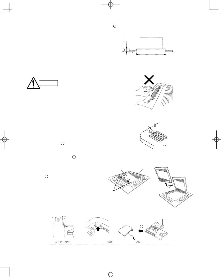
3-6-1. Before Installing the Ceiling Panel Checking the unit position
(1)Check that the ceiling hole is within this range: 33-55/64 × 33-55/64 to 35-53/64 × 35-53/64 in.
(2)Use the full-scale installation diagram (from the packaging) that was supplied with the unit to determine the positioning of the unit on the ceiling surface. If the positions of the ceiling surface and unit do not match, air leakage, water leakage, fl ap operation failure, or other problems may occur.
CAUTION
●Never place the panel face-down. Either hang it vertically or place it on top of a projecting object. Placing it face-down will damage the surface.
●Do not touch the flap or apply force to it. (This may cause flap malfunction.)
A must be within the range of 15/32" – 43/64" (Fig. 3-13)
If not within this range, malfunction or other trouble may occur.
|
|
|
|
|
|
|
|
|
|
|
|
|
|
|
|
|
|
|
|
|
|
|
|
|
Main unit |
|
|
|
|
|
|
|
|
|
|
|
|
|
|
|
|
A |
|
|
|
|
|
|
|
|
|
|
|
||
|
|
|
|
|
|
|
|
|
|
|
|
||
|
|
|
|
|
|
|
|
|
Ceiling opening |
|
|
||
|
|
|
|
|
|
|
|
|
|
|
dimension |
|
|
|
|
|
|
|
|
|
|
|
|
|
|
|
|
|
|
|
|
|
|
|
|
|
|
|
|
|
|
Ceiling side
Fig. 3-13
Flap
Fig. 3-14
Remove the air-intake grille and air filter from the ceiling panel. (Figs. 3-15, 3-16 and 3-17)
a)Remove the 2 screws on the latch of the air-intake grille. (Fig. 3-15)
b)Slide the air-intake grille catches in the direction shown by the arrows 1 to open the grille. (Fig. 3-16)
c)With the air-intake grille opened, remove the grille hinge from the ceiling panel by sliding it in the direction shown by the arrow 2 . (Fig. 3-17)
Removing the corner cover
a)Slide the corner cover to the direction shown by the arrow 1 to remove the corner cover.
(Fig. 3-18).
Screw
Latch
Fig. 3-15
Air-intake |
grille |
Ceiling panel |
1
1
2
Air-intake grille hinge
Fig. 3-16
Fig. 3-17
Ceiling panel
Corner cover
1
Push
|
|
|
|
|
|
|
|
Corner cover |
Strap |
||
|
|||
|
|
|
|
Fig. 3-18
13
|
|
|
|
|
|
|
|
|
|
|
|
|
|
VRF_Indoor_US.indb 13 |
|
2011/09/30 12:22:56 |
|
|
|
|
|
|
|
||||
|
|
|
|
|
|
|
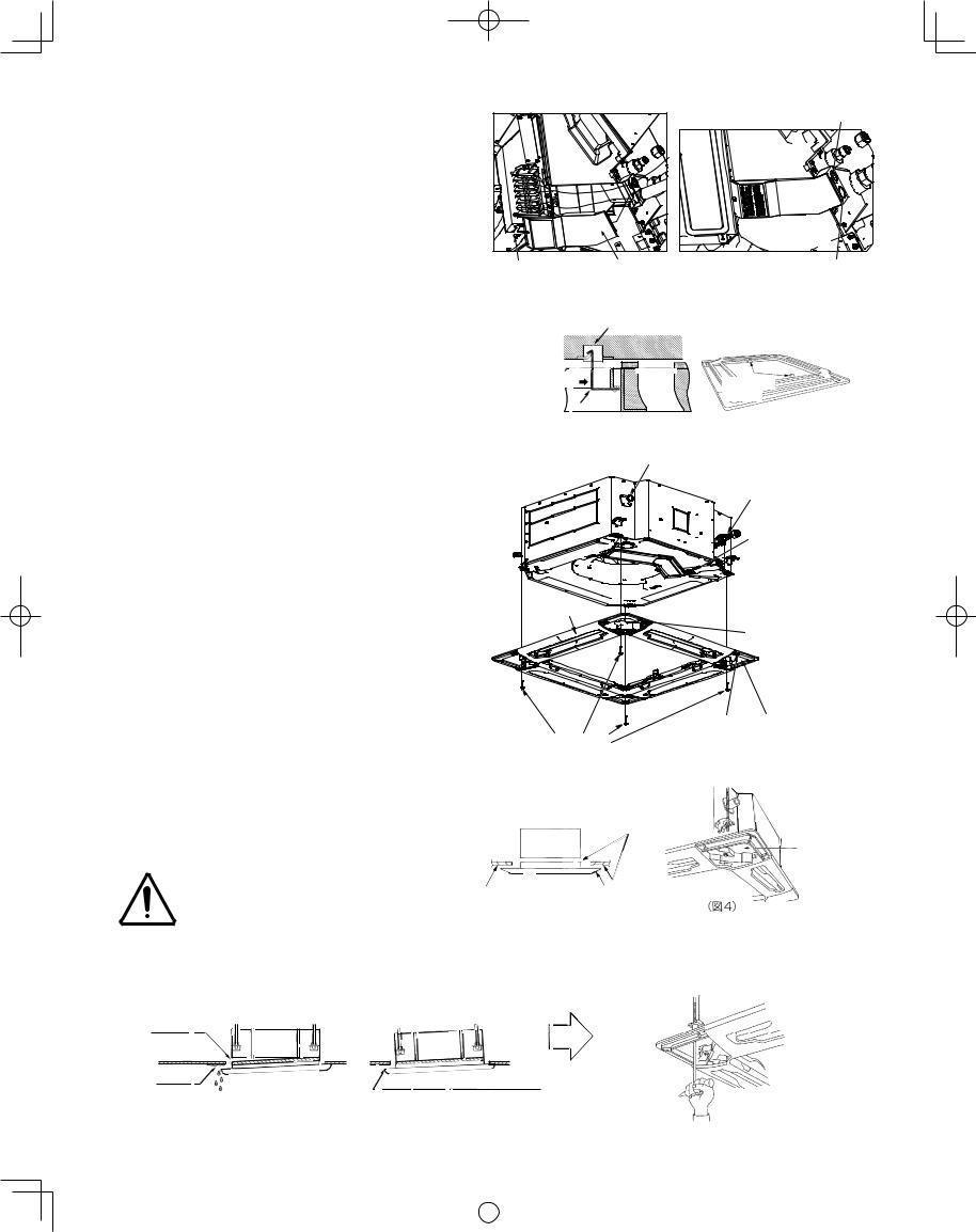
3-6-2. Installing the Ceiling Panel
After completing the wiring process, install the supplied wiring cover before installing the panel.
It is not possible to install the wiring cover after installing the panel.
The power must be turned ON in order to change the fl ap angle. (Do not attempt to move the fl ap by hand. Doing so may damage the fl ap.)
(1)Insert the temporary fasteners (stainless steel) on the inside of the ceiling panel into the square holes on the unit to temporarily fasten the ceiling panel in place.
(Fig. 3-20-1)
●The ceiling panel must be installed in the correct direction relative to the unit. Align the REF. PIPE and DRAIN marks on the ceiling panel corner with the correct positions on the unit.
●To remove the ceiling panel, support the ceiling panel while pressing the temporary fasteners toward the outside. (Fig. 3-20-1)
(2)Align the panel installation holes and the unit screw holes.
(3)Tighten the supplied washer head screws at the 4 panel installation locations so that the panel is attached tightly to the unit. (Fig. 3-20-2)
(4)Check that the panel is attached tightly to the ceiling.
●At this time, make sure that there are no gaps between the unit and the ceiling panel, or between the ceiling panel and the ceiling surface. (Fig. 3-21)
●If there is a gap between the panel and the ceiling, leave the ceiling panel attached and make fi ne adjustments to the installation height of the unit to eliminate the gap with the ceiling. (Fig. 3-21)
Inter-unit control wiring
Screw (supplied) |
Wiring cover (supplied) |
Power supply outlet |
M4-8 or 5/32" – 5/16" |
|
|
Fig. 3-19-1 |
Fig. 3-19-2 |
|
Square hole in unit
Push when  you remove
 Temporary
fastener
Temporary
fastener
Fig. 3-20-1
Drain tubing corner
Refrigerant tubing corner
Ceiling panel
Washer head screws
After completing the wiring process, install the supplied wiring cover
before installing the panel. It is not possible to install the wiring cover after installing the panel.
 DRAIN mark
REF. PIPE |
Panel installation hole |
mark |
(4 locations) |
Fig. 3-20-2
|
|
|
|
|
|
|
|
|
|
|
|
|
|
|
|
|
Insert a wrench |
|
|
|
|
|
|
|
|
|
|
|
|
|
|
|
|
|
|
||
|
|
|
|
|
|
|
|
|
|
|
|
|
|
|
|
|
or other tool into |
|
|
|
|
|
|
|
|
|
|
|
|
|
|
|
|
|
|
the corner cover |
|
|
|
|
|
|
|
|
|
|
|
Do not allow |
|
|
|
|
installation hole |
|||
|
|
|
|
|
|
Main unit |
|
|
|
|
|
gaps |
|
|
|
|
and make fine |
|
|
|
|
|
|
|
|
|
|
|
|
|
|
|
|
||||
|
|
|
|
|
|
|
|
|
|
|
|
|
|
|
|
|
adjustments to |
|
|
|
|
|
|
|
|
|
|
|
|
|
|
|
|
|
|
|
|
|
|
|
|
|
|
|
|
|
|
|
|
|
|
|
|
|
|
|
|
|
|
|
|
|
|
|
|
|
|
|
|
|
|
|
|
the unit nut. |
|
|
|
|
|
|
|
|
|
|
|
|
|
|
||||||
|
Ceiling surface |
Ceiling panel |
|
|
|
|
|
|
||||||||||
CAUTION |
|
|
|
|
|
|
||||||||||||
|
|
|
|
|
|
|||||||||||||
|
|
|
|
|
|
|
|
|
|
|
|
|
|
|
|
|
|
|
|
|
|
|
|
|
Fig. 3-21 |
|
|
Fig. 3-22 |
|||||||||
|
||||||||||||||||||
|
|
|
|
|
|
|
|
|||||||||||
●If the screws are not suffi ciently tightened, trouble such as that shown in the fi gure below may occur. Be sure to tighten the screws securely.
●If a gap remains between the ceiling surface and the ceiling panel even after the screws are tightened, adjust the height of the unit again.
The height of the unit can be adjusted from the ceiling panel corner hole, with the ceiling panel attached, to an extent that does not affect the unit levelness, the drain hose, or other elements.
Air leakage |
|
Air leakage from |
|
ceiling surface |
|
Staining |
Adjust so that there are no gaps. |
|
|
Condensation, water leakage |
Fig. 3-23 |
14
|
|
|
|
|
|
|
|
|
|
|
|
|
|
VRF_Indoor_US.indb 14 |
|
2011/09/30 12:22:57 |
|
|
|
|
|
|
|
||||
|
|
|
|
|
|
|
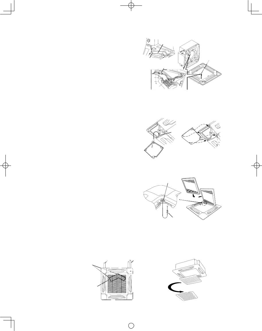
3-6-3. Wiring the Ceiling Panel
(1)Open the cover of the electrical component box.
(2)Connect the 7P wiring connector (red) from the ceiling panel to the connector in the unit electrical component box. (Fig. 3-24)
●If the connectors are not connected, the Auto fl ap will not operate. Be sure to connect them securely.
●Check that the wiring connector is not caught between the electrical component box and the cover.
●Check that the wiring connector is not caught between the unit and the ceiling panel.
3-6-4. How to Attach the Corner & Air-Intake Grille Attaching the corner cover and air-intake grille
A. Attaching the corner cover
(1)Check that the safety cord from the corner cover is fastened to the ceiling panel pin, as shown in the
fi gure. (Fig. 3-25)
(2)Use the supplied screws to attach the corner cover to the ceiling panel. (Fig. 3-25)
B. Attaching the air-intake grille
●To install the air-intake grille, follow the steps for Removing the grille in the reverse order. By rotating the air-intake grille, it is possible to attach the grille onto the ceiling panel from any of 4 directions. Coordinate the directions of the air-intake grilles when installing multiple units, and change the directions according to customer requests. (Fig. 3-26)
●When attaching the air-intake grille, be careful that the flap lead wire does not become caught.
●Be sure to attach the safety cord that prevents the air-intake grille from dropping off to the ceiling panel unit as shown in the figure at right.
●With this ceiling panel, the directions of the air-intake grille lattices when installing multiple units, and the position of the label showing the company name on the corner panel, can be changed according to
customer requests, as shown in the fi gure below. However, the optional wireless receiver kit can only be installed at the refrigerant-tubing corner of the ceiling unit. (Fig. 3-27)
(Direction that the unit faces has been changed to facilitate explanation.)
Electrical component box cover
Ceiling panel Screws wiring connector (3 locations)
Ceiling panel side
Mains side
Clamp
*Pass the wiring connector through the clamp to fasten it in place, as shown in the figure.
Fig. 3-24
Pin
Place the corner cover so that the 3 tabs fit into the holes in the ceiling panel.
Then fasten it in place with the supplied screws.
Fig. 3-25
Hole for ceiling panel hook
Hook that prevents
the grille from dropping
Fig. 3-26
Locations of the air-intake grille catches at |
|
|
|
|
|
|
|
|
|
|
|
|
|
|
|
|
|
|
|
|
the time the product is shipped. |
Unit drain hose side |
|
|
|
|
|
||||||||||||||
* The grille can be installed with these |
|
|
|
|
Unit refrigerant tube side |
|||||||||||||||
catches facing in any of 4 directions. |
|
|
|
|
|
|
|
|
|
|
|
|
|
|
|
|
|
|
|
Optional wireless receiver kit |
|
|
|
|
|
|
|
|
|
|
|
|
|
|
|
|
|
|
|
||
|
|
|
|
|
|
|
|
|
|
|
|
|
|
|
|
|
|
|
||
|
|
|
|
|
|
|
|
|
|
|
|
|
|
|
|
|
|
|
|
|
|
|
|
|
|
|
|
|
|
|
|
|
|
|
|
|
|
|
|
|
|
|
|
|
|
|
|
|
|
|
|
|
|
|
|
|
|
|
|
|
|
* Can only be installed |
|
|
|
|
|
|
|
|
|
|
|
|
|
|
|
|
|
|
|
|
in this position. |
Unit electrical component box |
|
|
|
|
|
|
|
|
|
|
|
|
|
|
|
|
|
|
|
Can be installed rotated 90˚ |
|
|
|
|
|
|
|
|
|
|
|
|
|
|
|
|
|
|
|
||
|
|
|
|
|
|
|
|
|
|
|
|
|
|
|
|
|
|
|
||
|
|
|
|
|
|
|
|
|
|
|
|
|
|
|
|
|
|
|
|
|
|
|
|
|
|
|
|
|
|
|
|
|
|
|
|
|
|
|
|
|
|
|
|
|
|
|
|
|
|
|
|
|
|
|
|
|
|
|
|
|
|
|
Fig. 3-27
15
|
|
|
|
|
|
|
|
|
|
|
|
|
|
VRF_Indoor_US.indb 15 |
|
2011/09/30 12:22:58 |
|
|
|
|
|
|
|
||||
|
|
|
|
|
|
|
3-6-5. Checking After Installation
●Check that there are no gaps between the unit and the ceiling panel, or between the ceiling panel and the ceiling surface. Gaps may cause water leakage and condensation.
●Check that the wiring is securely connected.
If it is not securely connected, the auto fl ap will not operate. (“P09” is displayed on the remote controller.) In addition, water leakage and condensation may occur.
3-6-6. When Removing the Ceiling Panel for Servicing
When removing the ceiling panel for servicing, remove the air-intake grille and air fi lter, disconnect the wiring connector inside the electrical component box, and then remove the 4 mounting screws.
3-6-7. Adjusting the Auto Flap
The air-direction louver on the ceiling panel outlet can be adjusted as follows.
●Adjust the louver to the desired angle using the remote controller. The louver also has an automatic air-sweeping mechanism.
NOTE
●Never attempt to move the louver by hand.
●Proper air fl ow depends on the location of the air conditioner, the layout of the room and furniture, etc. If cooling or heating seems inadequate, try changing the direction of the air fl ow.
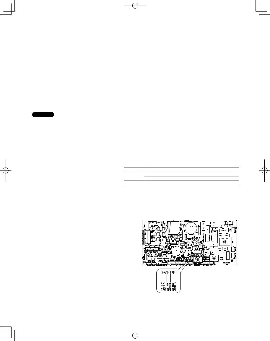
3-7. Special Remarks
DC Fan Tap Change Procedure
Be sure to turn OFF the power (at mains) before beginning the work below.
(1)In the table below, check the fi eld-supply parts that will be used. (If this setting is not made, the airfl ow may decrease and condensation may occur.)
Setting
(a)
Air shield material (for use with 3-direction discharge)*
Air shield material (for use when a discharge duct is connected)*
(b)Air shield material (for use with 2-direction discharge)*
* Use fi eld-supply air shield material.
Setting (a): Go to (2). Setting (b): Go to (3).
(2)Setting (a)
Open the cover of the electrical component box. Short the short-circuit pin TP3 (2P, yellow) on the indoor unit control PCB. (Fig. 3-28)
(3)Setting (b)
Open the cover of the electrical component box. Short the short-circuit pin TP6 (2P, white) on the indoor unit control PCB. (Fig. 3-28)
Indoor unit control PCB
* PCB model No.: CR-SXRP56B-B
Fig. 3-28
16
|
|
|
|
|
|
|
|
|
|
|
|
|
|
VRF_Indoor_US.indb 16 |
|
2011/09/30 12:22:58 |
|
|
|
|
|
|
|
||||
|
|
|
|
|
|
|
■ 4-Way Cassette 60 × 60 Type (Y1 Type)
3-8. Preparation for Suspending
This unit uses a drain pump. Use a level gauge to check that the unit is level.
3-9. Suspending the Indoor Unit
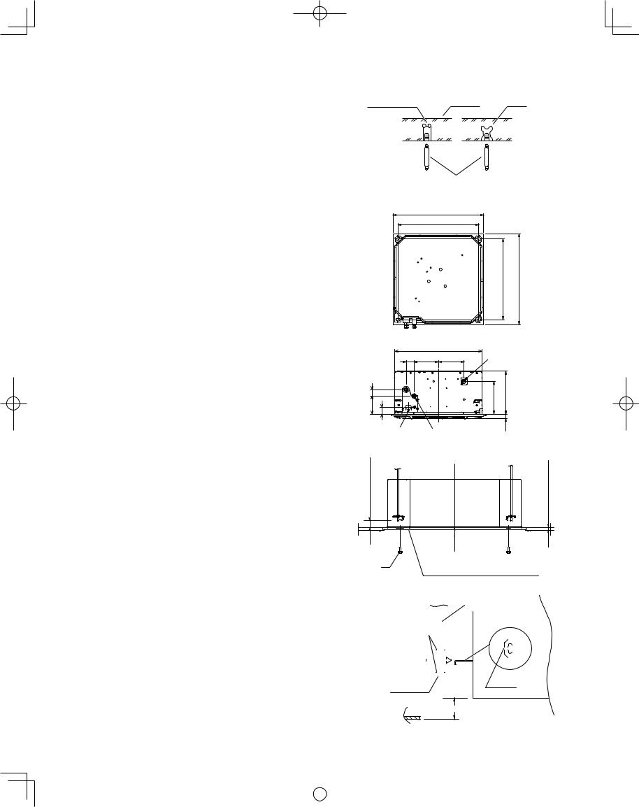
(1)Fix the suspension bolts securely in the ceiling using the method shown in the diagrams, by attaching them to the ceiling support structure, or by any other method that ensures that the unit will be securely and safely suspended. (Fig. 3-29)
(2)Follow the diagram to make the holes in the ceiling.
(3)Determine the pitch of the suspension bolts using the supplied full-scale installation diagram. The diagram shows the relationship between the positions of the suspension fi tting, unit, and panel. (Fig. 3-30)
3-10. Placing the Unit Inside the Ceiling
(1)When placing the unit inside the ceiling, determine the pitch of the suspension bolts using the supplied fullscale installation diagram. (Fig. 3-31)
Tubing and wiring must be laid inside the ceiling when suspending the unit. If the ceiling is already constructed, lay the tubing and wiring into position for connection to the unit before placing the unit inside the ceiling.
(2)The length of suspension bolts must be appropriate for a distance between the bottom of the bolt and the bottom of the unit of more than 19/32" as shown in the diagram. (Fig. 3-31)
(3)Thread the 3 hexagonal nuts and 2 washers (fi eld supply) onto each of the 4 suspension bolts as shown in the diagram. Use 1 nut and 1 washer for the upper side, and 2 nuts and 1 washer for the lower side, so that the unit will not fall off the suspension lugs.
(Fig. 3-32)
(4)Adjust so that the distance between the unit and the ceiling bottom is 33/64" to 45/64". Tighten the nuts on the upper side and lower side of the suspension lug. (Fig. 3-32)
(5)Remove the protective polyethylene used to protect the fan parts during transport.
17
Hole-in-anchor |
Concrete |
Insert |
Hole-in-plug |
Suspension bolt (M10 or 3/8") |
Fig. 3-29 |
(fi eld supply) |
23-5/8"
Ceiling opening dimensions
21-1/32" Suspension bolt pitch |
21-1/32" Suspension bolt pitch 23-5/8" Ceiling opening dimensions
|
|
22-41/64" |
Drain tube |
|
|
2-3/32" |
6-19/64" 6-11/16" |
connection port |
|
|
(outer dia ø1-1/32") |
|||
|
|
|
||
39/64" 1-49/64" |
1-49/64" |
8-15/32" |
11-9/64 |
|
4- |
|
|
3/16" |
|
Power supply port |
Refrigerant tubing joint |
Fig. 3-30 |
||
1- |
|
|||
|
|
(liquid side) |
|
|
|
|
ø1/4 (fl ared) |
|
|
Over 19/32" |
33/64" – 45/64" |
Supplied bolt |
Full-scale installation diagram |
||||||||||||||||||||||
(printed on top of container box) |
|||||||||||||||||||||||
|
|
|
|||||||||||||||||||||
|
|
|
|
|
|
|
|
|
|
|
|
|
|
|
|
|
|
|
|
|
Fig. 3-31 |
||
|
|
|
|
|
|
|
|
|
|
|
|
|
Suspension bolt |
||||||||||
|
|
|
|
|
|
|
|
|
|
|
|
|
|
|
|
|
|
|
|
|
|
||
|
|
|
|
|
|
|
|
|
|
|
|
|
|
|
|
|
|
|
|
|
|
|
|
Nuts and washers |
|
|
|
|
|
|
|
|
|
|
Suspension lug |
||||||||||||
(used for upper and lower) |
|
|
|
|
|
|
|
|
|
|
|
|
|
|
|
|
|
|
|
|
|||
|
|
|
|
|
|
|
|
|
|
|
|
|
|
|
|
|
|
|
|
||||
|
|
|
|
|
|
|
|
|
|
|
|
|
|
|
|
|
|
|
|
|
|
|
|
|
|
|
|
|
|
|
|
|
|
|
|
|
|
|
|
|
|
|
|
|
|
|
|
|
|
|
|
|
|
|
|
|
|
|
|
|
|
|
|
|
|
|
|
|
|
|
|
|
|
|
|
|
|
|
|
|
|
|
|
|
|
|
|
|
|
|
|
|
|
|
|
|
|
|
|
|
|
|
|
|
|
|
|
|
|
|
|
|
|
|
|
|
|
|
|
|
|
|
|
|
|
|
|
|
|
|
|
|
|
|
|
|
|
|
|
|
|
|
|
|
|
|
|
|
|
|
|
|
|
|
|
|
|
|
|
|
|
|
|
|
|
|
|
|
|
|
|
|
|
|
|
|
|
|
|
|
|
|
|
|
|
|
|
|
|
|
|
|
|
|
|
|
|
|
|
|
|
|
|
|
|
|
|
|
|
|
|
|
|
|
|
Notch
Double nut
33/64" – 45/64"
Fig. 3-32
|
|
|
|
|
|
|
|
|
|
|
|
|
|
VRF_Indoor_US.indb 17 |
|
2011/09/30 12:22:58 |
|
|
|
|
|
|
|
||||
|
|
|
|
|
|
|
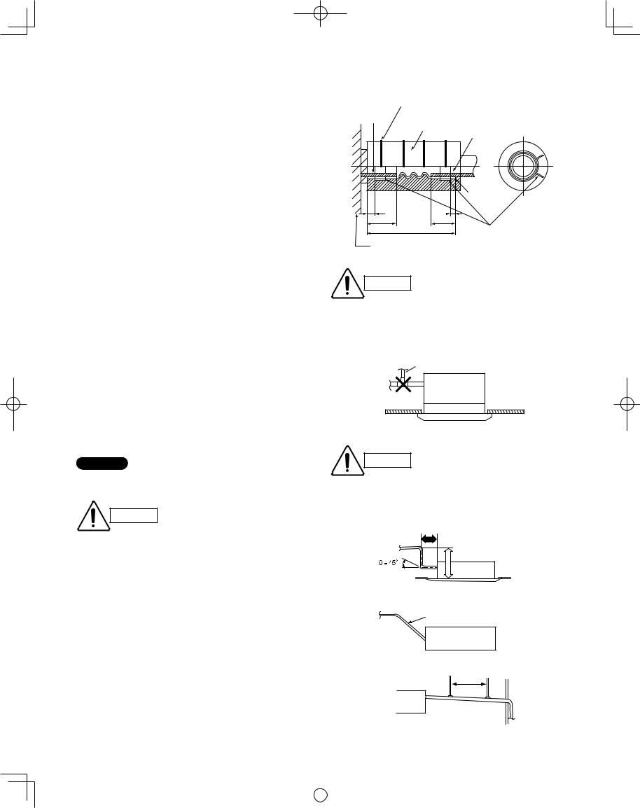
3-11. Installing the Drain Piping
(1)Prepare standard hard PVC pipe (O.D. 1-1/32") for the drain and use the supplied hose band to prevent water leaks. (Fig. 3-33)
The PVC pipe must be purchased separately.
The transparent drain part on the unit allows you to check drainage.
(2)Installing the drain hose
●To install the drain hose, fi rst place 1 of the 2 hose bands over the unit drain port and the other hose band over the hard PVC pipe (not supplied). Then connect both ends of the supplied drain hose. (Fig. 3-33)
●On the unit drain side, grasp the hose band with pliers and insert the drain hose all the way to the base.
●If other commercially available hose bands are used, the drain hose may become pinched or wrinkled and there is danger of water leakage. Therefore be sure to use the supplied hose bands. When sliding the hose bands, be careful to avoid scratching the drain hose.
●Do not use adhesive when connecting the supplied drain hose to the drain port (either on the main unit or the PVC pipe).
Reasons: 1. It may cause water to leak from the connection. Since the connection is slippery just after the adhesive has been applied, the pipe easily slips off.
2.The pipe cannot be removed when maintenance is needed.
●Wrap the hose with the supplied drain hose insulation and use the 4 twist ties so that the hose is insulated with no gaps.
●Do not bend the supplied drain hose 90° or more. The hose may slip off.
NOTE
Make sure the drain pipe has a downward gradient (1/100 or more) and that there are no water traps.
CAUTION
●In cases where it is necessary to raise the height of the drain piping, the drain piping can be raised to a maximum height of 2.78 ft. above the bottom surface of the ceiling. Under no conditions attempt to raise it higher than 2.78 ft. above the bottom surface of the ceiling. Doing so will result in water leakage. (Fig. 3-34)
●Do not use natural drainage.
●Do not install the pipe with an upward gradient from the connection port. This will cause the drain water to flow backward and leak when the unit is not operating.
(Fig. 3-35)
●Do not apply force to the piping on the unit side when connecting the drain pipe. The pipe should not be allowed to hang unsupported from its connection to the unit. Fasten the pipe to a wall, frame, or other support as close to the unit as possible. (Fig. 3-36)
●Provide insulation for any pipes that are run indoors.
18
Twist tie
(4 ties, supplied)
|
Drain hose |
Hard PVC pipe |
Position to |
Drain port |
insulation |
(equivalent to |
|
|
(supplied) |
O.D. 1-1/32") |
fasten hose |
|
|
(Field supply) |
bands |
|
|
Drain hose |
|
|
|
(supplied) |
|
13/64" |
13/64" |
|
|
63/64" |
63/64" |
|
|
|
5-33/64" |
Hose band |
|
|
|
(2 bands, supplied) |
|
Unit |
|
|
Fig. 3-33 |
|
|
|
|
● Attach so that the hose band
CAUTION fastener is on the side of the drain port.
●Attach the hose bands so that each is approximately 13/64" to 63/64" from the end of the supplied drain hose.
Air bleeder prohibited
● Do not install an air bleeder as
CAUTION this may cause water to spray from the drain pipe outlet.
1 ft. or less |
2.78 ft. or less |
* Length of supplied drain hose = 5-33/64" |
Fig. 3-34 |
 Upward gradient prohibited
Fig. 3-35
Support bracket
Fig. 3-36
|
|
|
|
|
|
|
|
|
|
|
|
|
|
VRF_Indoor_US.indb 18 |
|
2011/09/30 12:22:58 |
|
|
|
|
|
|
|
||||
|
|
|
|
|
|
|
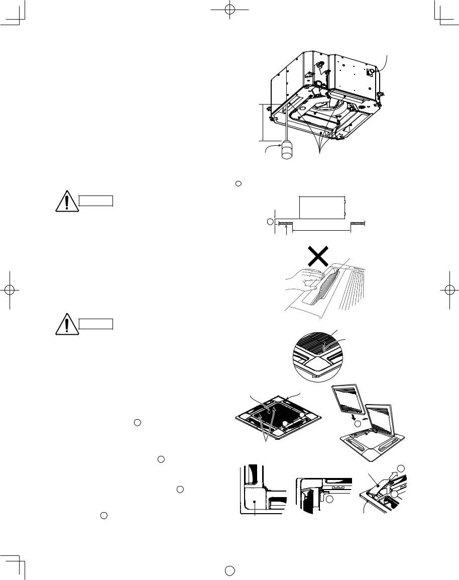
3-12. Checking the Drainage |
Water drain |
|
After wiring and drain piping are completed, use the following procedure to check that the water will drain smoothly. For this, prepare a bucket and wiping cloth to catch and wipe up spilled water.
(1) Connect power to the power terminal board (R, S terminals) inside the electrical component box.
(2) Slowly pour approx. 0.13 gal of water into the drain |
Over |
|
|
pan to check drainage. (Fig. 3-37) |
3-15/16" |
|
|
|
|
|
|
(3) Short the check pin (CHK) on the indoor control board |
|
|
|
and operate the drain pump. Check the water fl ow |
|
|
|
through the transparent drain pipe and see if there is |
Plastic container |
Drain pan outlet |
|
any leakage. |
for water intake |
Water |
|
|
Fig. 3-37 |
||
|
(Approx. 0.13 gal) |
||
|
|
(4) When the check of drainage is complete, open the |
|
|
|
check pin (CHK) and remount the tube cover. |
A must be within the range of 33/64" to 45/64". (Fig. 3-38) |
||
|
Be careful since the fan will start |
If not within this range, malfunction or other trouble may occur. |
|
CAUTION |
when you short the pin on the |
|
Main unit |
|
indoor control board. |
|
|
|
|
A |
Ceiling opening |
3-13. How to Install the Ceiling Panel |
|
dimension |
|
|
Fig. 3-38 |
||
|
|
Ceiling side |
|
Checking the unit position
(1) Check that the ceiling hole is within this range:
Flap
23-5/8" × 23-5/8"
(2)Confi rm that the position of the indoor unit and the ceiling as shown in the diagram. If the positions of the ceiling surface and unit do not match, air leakage, water leakage, fl ap operation failure, or other problems may occur.
Fig. 3-39
CAUTION
●Never place the panel face-down. Either hang it vertically or place it on top of a projecting object. Placing it facedown will damage the surface.
Screw |
Latch |
● Do not touch the flap or apply force to it. (This may cause flap malfunction.)
3-13-1. Before Installing the Ceiling Panel
Ceiling panel
Air-intake grille
(1) Remove the air-intake grille and air fi lter from the ceiling panel.
a)Slide the air-intake grille catches in the direction shown by the arrows 1 to open the grille.
(Fig. 3-40)
1 |
1 |
2 |
b)With the air-intake grille opened, remove the grille hinge from the ceiling panel by sliding it in the direction shown by the arrow 2 . (Fig. 3-41)
Air-intake grille hinge
Fig. 3-40 |
Fig. 3-41 |
|
(2)Removing the corner cover
a)Remove the screws on the corner and slide the latches in the direction of the arrow 1 to disconnect the hinges (3 locations). (Fig. 3-42) Then, remove the air-intake grille in the direction of the arrow 2 . (Fig. 3-43)
Corner cover |
2 |
|
1 |
|
1 |
|
Push |
Corner cover |
Ceiling panel |
|
Fig. 3-42 |
Fig. 3-43 |
19
|
|
|
|
|
|
|
|
|
|
|
|
|
|
VRF_Indoor_US.indb 19 |
|
2011/09/30 12:22:59 |
|
|
|
|
|
|
|
||||
|
|
|
|
|
|
|
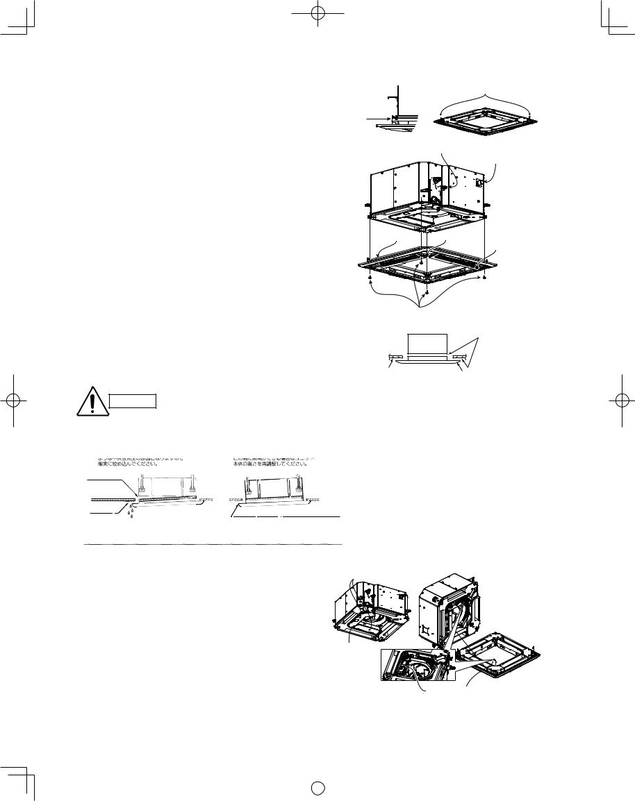
3-13-2. Installing the Ceiling Panel
The power must be turned ON in order to change the fl ap angle. (Do not attempt to move the fl ap by hand. Doing so may damage the fl ap.)
(1)Hang the temporary latches on the inside of the ceiling panel to the receptacle on the unit to temporarily attach the ceiling panel in place. (Fig. 3-44)
●The ceiling panel must be installed in the correct direction relative to the unit. Align the REF. PIPE and DRAIN marks on the ceiling panel corner with the correct positions on the unit.
(2)Align the panel installation holes and the unit screw holes. (Fig. 3-45)
(3)Tighten the supplied washer head screws at the 4 panel installation locations so that the panel is attached tightly to the unit.
(4)Check that the panel is attached tightly to the ceiling. (Fig. 3-46)
●At this time, make sure that there are no gaps between the unit and the ceiling panel, or between the ceiling panel and the ceiling surface.
Temporary latches
Temporary latch
Fig. 3-44
Refrigerant tubing joint
Drainage check
Ceiling panel |
REF. mark |
|
DRAIN mark |
Fig. 3-45
Panel installation hole
(4 locations)
Washer head screws
●If there is a gap between the panel and the ceiling, leave the ceiling panel attached and make fi ne adjustments to the installation height of the unit to eliminate the gap with the ceiling.
Main unit |
Do not allow |
|
gaps |
|
|
Ceiling surface |
Ceiling panel |
Fig. 3-46 |
CAUTION
● If the screws are not suffi ciently |
● If a gap remains between the ceiling |
|
||||||||||||||||||
|
tightened, trouble such as that shown |
surface and the ceiling panel even |
|
|||||||||||||||||
|
in the fi gure below may occur. Be sure |
after the screws are tightened, adjust |
|
|||||||||||||||||
|
to tighten the screws securely. |
the height of the unit again. |
|
|||||||||||||||||
|
|
|
|
|
|
|
|
|
|
|
|
|
|
|
|
|
|
|
|
|
|
Air leakage |
|
|
|
|
|
|
|
|
|
|
|
|
|
|
|||||
|
|
|
|
|
|
|
|
|
|
|
|
|
|
|
||||||
|
|
|
|
|
|
|
|
|
|
|
|
|
|
|
|
|
|
|||
Air leakage from |
|
|
|
|
|
|
|
|
|
|
|
|
|
|
|
|||||
|
|
|
|
|
|
|
|
|
|
|
|
|
|
|
||||||
|
|
|
|
|
|
|
|
|
|
|
|
|
|
|
||||||
|
|
|
|
|
|
|
|
|
|
|
|
|
|
|
||||||
ceiling surface |
|
|
|
|
|
|
|
|
|
|
|
|
|
|
|
|||||
|
|
Staining |
|
|
|
|
|
|
|
|
|
|
|
|
|
|
|
Fig. 3-47 |
||
|
|
|
|
|
|
|
|
|
|
|
|
Adjust so that there are no gaps. |
||||||||
|
|
|
Condensation, water leakage |
|
||||||||||||||||
|
|
|
|
|
|
|
|
|
||||||||||||
|
|
|
|
|
|
|
|
|
|
|||||||||||
|
|
|
|
|
|
|
|
|
|
|
|
|
|
|
|
|
|
|
|
|
|
|
|
|
|
|
|
|
|
|
|
|
|
|
|
|
|
|
|
|
|
3-13-3. Wiring the Ceiling Panel
(1)Open the cover of the electrical component box for control PCB.
(2)Connect the 7P wiring connector (red) from the ceiling panel to the connector on the control PCB in the unit electrical component box. (Fig. 3-48)
●If the connectors are not connected, the Auto fl ap will not operate. Be sure to connect them securely.
●Check that the wiring connector is not caught between the electrical component box and the cover.
●Check that the wiring connector is not caught between the unit and the ceiling panel.
(Direction that the unit faces has been changed to facilitate explanation.)
Electrical component box cover
Screws
(3 locations)
Fig. 3-48
Ceiling panel wiring connector
* Pass the wiring connector through the clamp to fasten it in place, as shown in the fi gure.
20
|
|
|
|
|
|
|
|
|
|
|
|
|
|
VRF_Indoor_US.indb 20 |
|
2011/09/30 12:23:01 |
|
|
|
|
|
|
|
||||
|
|
|
|
|
|
|
3-13-4. How to Attach the Corner & Air-Intake Grille
Attaching the corner cover and air-intake grille
A. Attaching the corner cover
(1)Check that the safety cord from the corner cover is fastened to the ceiling panel pin, as shown in the
fi gure. (Fig. 3-49)
(2)Use the supplied screws to attach the corner cover to the ceiling panel.
B. Attaching the air-intake grille
●To install the air-intake grille, follow the steps for Removing the grille in the reverse order. By rotating the air-intake grille, it is possible to attach the grille onto the ceiling panel from any of 4 directions. Coordinate the directions of the air-intake grilles when installing multiple units, and change the directions according to customer requests. (Fig. 3-50)
●When attaching the air-intake grille, be careful that the flap lead wire does not become caught.
●Be sure to attach the safety cord that prevents the air-intake grille from dropping off to the ceiling panel unit as shown in the figure at right.
●With this ceiling panel, the directions of the air-intake grille lattices when installing multiple units, and the position of the label showing the company name on the corner panel, can be changed according to customer requests, as shown in the fi gure below. However, the optional wireless receiver kit can only be installed at the refrigerant-tubing corner of the ceiling unit. (Fig. 3-51)
Pin
Fig. 3-49
Place the corner cover so that the 3 tabs fi t into the holes in the ceiling panel.
Then fasten it in place with the supplied screws.
Hole for ceiling panel hook
Hook that prevents the
grille from dropping
Fig. 3-50
Locations of air-intake grille hinges * The grille can be installed
Refrigerant tube side |
with these hinges facing |
|
in any of 4 directions. |
||
|
Optional wireless receiver kit |
Drain pipe side |
|
|
* Only this area is possible |
|
for installation. |
|
Electrical component box 

 for power PCB


Electrical component box for control PCB
3-13-5. Checking After Installation
Can be installed rotated 90°
Fig. 3-51
●Check that there are no gaps between the unit and the ceiling panel, or between the ceiling panel and the ceiling surface. Gaps may cause water leakage and condensation.
●Check that the wiring is securely connected.
If it is not securely connected, the auto fl ap will not operate. (“P09” is displayed on the remote controller.) In addition, water leakage and condensation may occur.
3-13-6. When Removing the Ceiling Panel for Servicing
When removing the ceiling panel for servicing, remove the air-intake grille and air fi lter, disconnect the wiring connector inside the electrical component box, and then remove the 4 mounting screws.
3-13-7. Adjusting the Auto Flap
The air-direction louver on the ceiling panel outlet can be adjusted as follows.
●Adjust the louver to the desired angle using the remote controller. The louver also has an automatic air-sweeping mechanism.
NOTE
●Never attempt to move the louver by hand.
●Proper air fl ow depends on the location of the air conditioner, the layout of the room and furniture, etc. If cooling or heating seems inadequate, try changing the direction of the air fl ow.
21
|
|
|
|
|
|
|
|
|
|
|
|
|
|
VRF_Indoor_US.indb 21 |
|
2011/09/30 12:23:04 |
|
|
|
|
|
|
|
||||
|
|
|
|
|
|
|
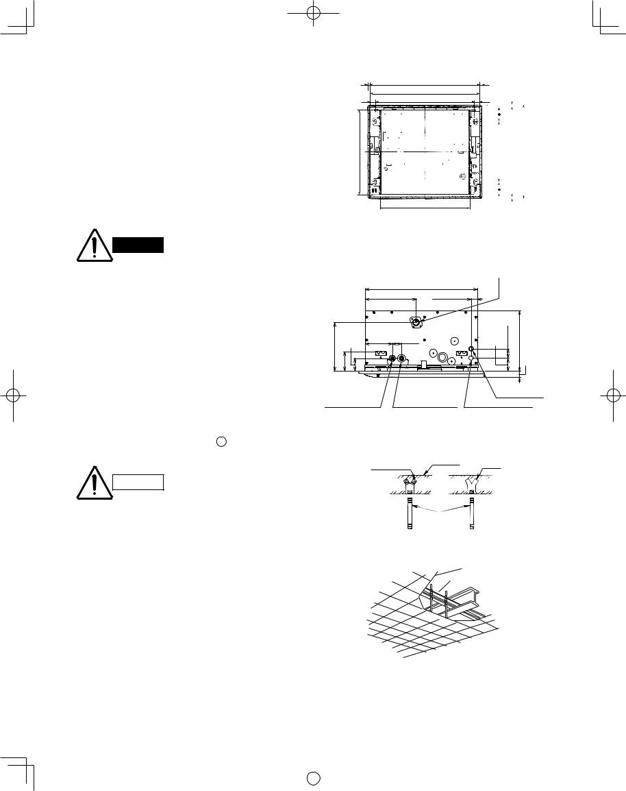
■ 1-Way Cassette Type (D1 Type)
3-14. Suspending the Indoor Unit
(1)Follow the diagrams to make the holes in the ceiling. (Figs. 3-52 and 3-53)
(2)Depending on the ceiling type:
●Insert suspension bolts as shown in Fig. 3-54 or
●Use existing ceiling supports or construct a suitable support as shown in Fig. 3-55.
●Make sure that the length of suspension bolts from the bottom of the unit is 19/32" or more. (Fig. 3-56)
29-59/64 (Panel outer dimensions)
28-47/64 (Ceiling opening dimension)
1-27/64 25-63/64 (Suspension bolt pitch)
22-3/64
23-5/8
|
|
|
|
|
19/32 |
|
|
|
|
(1-27/64) |
|
|
|||||||
|
|
|
|
|
|
|
|
|
|
|
|
|
|
|
|
|
|
24-13/32 (Outline dimension of panel) |
|
|
|
|
|
|
23-15/64 (Ceiling opening dimension) |
|
|
||
|
|
|
|
|
|||||
|
|
|
|
|
|
|
|||
|
|
15-3/4 (Suspension bolt pitch) |
|
||||||
|
|
|
|
|
|||||
|
|
|
|
|
|
|
|
||
|
|
|
|
|
|||||
|
|
|
|
|
|
|
|
|
|
47/64 |
|
|
19/32 |
|
|
|
|
||
|
|
|
|
|
|
||||
3- |
|
|
|
|
|
|
|
||
Unit: in.
WARNING
It is important that you use extreme care in supporting the indoor unit from the ceiling. Ensure that the ceiling is strong enough to support the weight of the unit. Before hanging the unit, test the strength of each attached suspension bolt.
(3)Calculate the suspension bolt pitch using the full-scale installation diagram (printed on the package). The relationship between the positions of the suspension lugs, unit, and ceiling panel is as shown in Fig. 3-53.
(4)Cut the ceiling material, if necessary. (Figs. 3-52 and 3-53)
If the system requires fresh air to be drawn into the unit, cut and remove the insulation (both externally and internally) at the location shown as A in Figs. 3-57 and 3-58.
CAUTION
When making the cuts to the insulation, be careful not to damage the drain pan.
22
Fig. 3-52
Drain pipe connection
(Be sure to connect the supplied flexible hose.)
|
|
|
|
|
22-3/64 |
|
|
|
|
|
|
|
10-1/32 |
1-19/64 |
|
|
|
|
|
29/64-9 |
3/16- |
-231/64 |
5-19/64 |
1-49/64 |
2-9/16 |
49/64-1 |
19/64-12 |
3/16-1 |
|
|
|
|
|
|
|
|
|||
|
3 |
|
|
|
|
|
|
|
|
Flared refrigerant |
Flared refrigerant |
Inter-unit |
||
connection outlet |
connection outlet |
Control Wiring |
||
(liquid tube) |
(gas tube) |
Power supply outlet |
||
|
|
|
Unit: in. |
|
|
|
Fig. 3-53 |
|
|
Hole-in-anchor |
Concrete |
|
||
Hole-in-plug |
Insert |
|||
|
||||
Suspension bolt (M10 or 3/8")
Fig. 3-54
Ceiling tiles
Ceiling support
Fig. 3-55
|
|
|
|
|
|
|
|
|
|
|
|
|
|
VRF_Indoor_US.indb 22 |
|
2011/09/30 12:23:05 |
|
|
|
|
|
|
|
||||
|
|
|
|
|
|
|
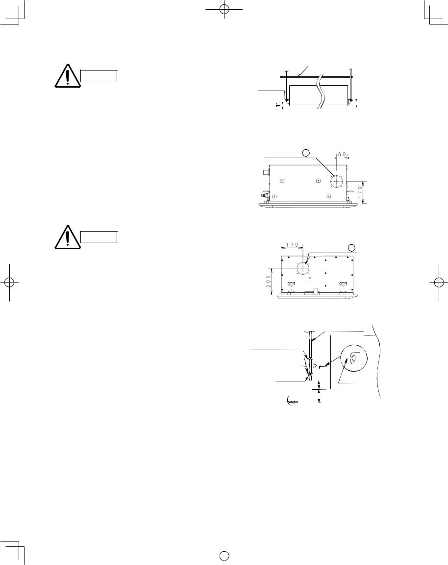
3-15. Placing the Unit Inside the Ceiling
Be sure to use a level gauge CAUTION and confirm that the unit is
level. If it is not level, water leakage may occur.
(1)Use the supplied M5 or 3/16" screws (4) to attach the full-scale installation diagram to the indoor unit suspension lugs, in order to obtain the ceiling opening dimensions for suspending the unit. (Fig. 3-56)
Caution: Piping and wiring work must be performed inside the ceiling after the unit is suspended. Therefore if the ceiling is already installed, the wiring and piping work should be completed up to the connection points prior to suspending the unit.
(2)Attach the special washers (supplied) and nuts (fi eld supply) to the suspension bolts (4 locations).
CAUTION
●Use M10 or 3/8" nuts.
●The length of the suspension bolts must be such that there is a space of at least 19/32" below the bottom of the suspension lugs, as shown in Fig. 3-56. If the length of the suspension bolts is too long, the bolts may interfere with the ceiling panel and louver motor, preventing their installation.
(3)Thread the 3 hexagonal nuts and 2 washers (fi eld supply) onto each of the 4 suspension bolts as shown in Fig. 3-59. Use 1 nut and 1 washer for the upper side, and 2 nuts and 1 washer for the lower side, so that the unit will not fall off the suspension lugs.
(4)Lift up the indoor unit and fi t the suspension bolts into the notches in the suspension lugs.
(5)Adjust so that the distance between the bottom of the indoor unit suspension lugs and the bottom of the ceiling panel is 25/32-1". Then tighten the nuts above and below each suspension lug. The full-scale installation diagram can be used to help adjust the height of the indoor unit.
23
Full-scale installation diagram
Suspension
lug
|
|
|
|
|
|
|
|
|
|
|
|
|
|
|
|
|
|
|
|
|
|
|
|
|
|
|
|
|
|
|
|
|
|
|
|
25/32 – 1 in. |
over 19/32 in. |
||||||||||
|
|
|
|
|
|
|
|||||
|
|
|
|
Fig. 3-56 |
|
|
|
|
|
|
|
For fresh air intake |
|
|
|
|
|
|
|
||||
(ø3-15/16 hole) A |
|
|
3-5/32 |
||||||||
|
|
||||||||||
|
|
|
|
|
|
|
|||||
|
|
|
|
|
|
|
|
|
|
|
|
|
|
|
|
|
|
|
|
|
|
|
|
|
|
|
|
|
|
|
|
|
|
6-11/16 |
|
|
|
|
|
|
|
|
|
|
|
|
|
|
|
|
|
|
Unit: in. |
|
|
|
|
|
|
|
|
|
|
|
|
|
|
|
|
|
|
|
|
|
Fig. 3-57 |
||||||||
|
|
|
|
|
|
|
|
For fresh air intake |
||||||
|
|
|
|
|
6-11/16 |
|
(ø3-15/16 hole) A |
|||||||
|
|
|
|
|
|
|
|
|||||||
|
|
|
|
|
|
|
|
|
|
|
|
|
|
|
|
|
|
|
|
|
|
|
|
|
|
|
|
|
|
|
|
|
|
|
|
|
|
|
|
|
|
|
|
|
|
8-1/16 |
|
|
|
|
|
|
|
|
|
|
|
|
|
|
|
|
|
|
|
|
|
|
|
|
|
|
|
Unit: in. |
|
|
|
|
|
|
|
|
|
|
|
|
|
|
|
|
|
|
|
|
|
Fig. 3-58 |
||||||||
|
|
|
|
|
|
|
|
|
Suspension bolt |
|||||
Nuts and washers |
|
|
|
Suspension lug |
||||||||||
(Used above and below.)
Double nuts |
|
|
|
|
Notch |
over 19/32" |
|
|
|
|
|
|
|
|
|
||
|
|
|
|
|
|
|
|
||||
|
|
25/32-1" |
|||
|
|
|
|
|
|
Fig. 3-59
|
|
|
|
|
|
|
|
|
|
|
|
|
|
VRF_Indoor_US.indb 23 |
|
2011/09/30 12:23:06 |
|
|
|
|
|
|
|
||||
|
|
|
|
|
|
|
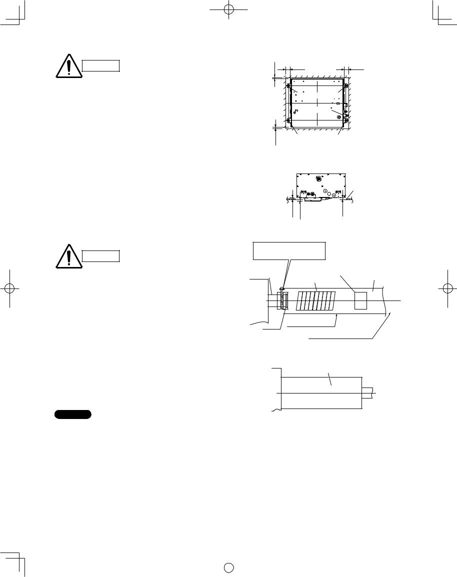
CAUTION
●The indoor unit includes a drain pump. Be sure to use a level gauge and verify that the unit is level.
●Before inserting the ceiling material, complete as much of the drain piping work and refrigerant tubing work as possible.
(6)The distance between the unit and the opening of the ceiling and the distance between the bottom
surface of the ceiling and the bottom surface of the fl ange of the unit should follow the dimensions given in Figs. 3-60 and 3-61.
3-16. Installing the Drain Piping
(1)Prepare standard hard PVC pipe (O.D. 1-1/4") for the drain and use the supplied drain hose and hose band to prevent water leaks.
The PVC pipe must be purchased separately. The unit’s transparent drain port allows you to check drainage. (Fig. 3-62)
CAUTION
●Do not use adhesive at the drain connection port on the indoor unit.
●Insert the drain pipe until it contacts the socket, as shown in the fi gure at right, then secure it tightly with the hose band.
●Tighten the hose clamps so their locking nuts face upward. (Fig. 3-62)
●Do not use the supplied drain hose bent at a 90° angle. (The maximum permissible bend is 45°.)
●Check the drainage at the unit drain port (transparent).
(2)After checking the drainage, wrap the supplied packing and drain pipe insulator around the pipe, then secure it with the supplied clamps. (Fig. 3-63)
19/32 |
2-1/8 |
2-1/8 |
|
|
|
|
Suspension bolts |
|
|
Tubing side |
|
19/32 |
Suspension bolts |
Unit: in. |
|
||
|
|
|
|
Fig. 3-60 |
|
Ceiling
 material
25/32 |
25/32 |
25/32 |
Fig. 3-61
Align the hose band with end of the hose, and tighten so that it does not contact the bead.
Drainage check |
|
|
|
|
|
|
|
|
Hard PVC pipe |
|
section on drain |
|
|
|
Supplied |
PVC adhesive |
VP-25 |
||||
port (transparent) |
|
|
|
(Field supply) |
||||||
|
|
|
|
|
|
|
||||
|
|
|
|
drain hose |
|
|
|
|
||
|
|
|
|
|
|
|
|
|
|
|
|
|
|
|
|
|
|
|
|
|
|
|
|
|
|
|
|
|
|
|
|
|
|
|
|
|
|
|
|
|
|
|
|
|
|
|
|
|
|
|
|
|
|
|
|
|
|
|
|
|
|
|
|
|
|
Packing (supplied)
Bead
Drain insulator (supplied)
Fig. 3-62
Drain insulator (supplied)
NOTE |
|
Make sure the drain pipe has a downward gradient (1/100 |
Fig. 3-63 |
or more) and that there are no water traps. |
|
24
|
|
|
|
|
|
|
|
|
|
|
|
|
|
VRF_Indoor_US.indb 24 |
|
2011/09/30 12:23:06 |
|
|
|
|
|
|
|
||||
|
|
|
|
|
|
|

CAUTION
●Do not install an air bleeder as this may cause water to spray from the drain pipe outlet. (Fig. 3-64)
●In cases where it is necessary to raise the height of the drain piping, the drain piping can be raised to a maximum height of 33-15/32" above the bottom surface of the ceiling. Under no conditions attempt to raise it higher than 33-15/32" above the bottom surface of the ceiling. Doing so will result in water leakage. (Fig. 3-65)
●Do not use natural drainage.
●Do not install the pipe with an upward gradient from the connection port. This will cause the drain water to flow backward and leak when the unit is not operating. (Fig. 3-66)
●Do not apply force to the piping on the unit side when connecting the drain pipe. The pipe should not be allowed to hang unsupported from its connection to the unit. Fasten the pipe to a wall, frame, or other support as close to the unit as possible. (Fig. 3-67)
●Provide insulation for any pipes that are run indoors.
Refer to “■ SUPPLEMENT ON DRAIN PIPING”.
3-17. Checking the Drainage
After wiring and drain piping are completed, use the following procedure to check that the water will drain smoothly. For this, prepare a bucket and wiping cloth to catch and wipe up spilled water.
(1)Connect power to the power terminal board (R, S terminals) inside the electrical component box.
(2)Slowly pour approx. 0.2 gal of water into the drain pan using a siphon pump through the air outlet grille. (Fig. 3-68)
(3)Short the check pin (CHK) on the indoor control board and operate the drain pump. Check the water fl ow through the transparent drain pipe and see if there is any leakage.
Be careful since the fan will start CAUTION when you short the pin on the
indoor control board.
(4)When the drainage check is complete, open the check pin (CHK) and remount the insulator.
The bottom drain port is for use CAUTION only during test runs and servicing
inspections. Do not connect the drain pipe to the bottom drain port.
25
Air bleed valve
Fig. 3-64
11-13/16" or less
33-15/32" or less
0 – 45°
* Length of supplied drain hose = 9-27/32"
Fig. 3-65
Upward gradient prohibited
Fig. 3-66
Support
bracket
Fig. 3-67
Drainage check
Drain tube connection (transparent)

 Discharge port water (approx. 0.2 gal)
Fig. 3-68
|
|
|
|
|
|
|
|
|
|
|
|
|
|
VRF_Indoor_US.indb 25 |
|
2011/09/30 12:23:06 |
|
|
|
|
|
|
|
||||
|
|
|
|
|
|
|
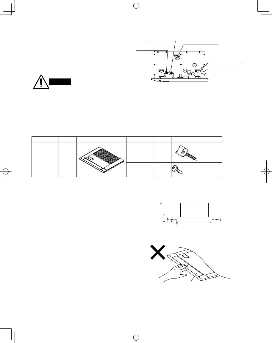
3-18. Electrical Power Wiring
(1) Wiring connections
The power inlet is on the side of the indoor unit where the refrigerant tubing is located. The electrical component box is on the lower air intake surface of the indoor unit. (Fig. 3-69)
(2) Wiring
WARNING
Refrigerant tubing joint |
Drain pipe connection |
(gas tube) |
(Be sure to connect the |
Refrigerant tubing joint |
supplied flexible hose.) |
|
|
(liquid tube) |
|
|
Inter-unit Control Wiring |
|
Power supply outlet |
Fig. 3-69
●Route the power wiring into the indoor unit through the power inlet on the side of the unit. At this time, be sure that the wiring passes through the power inlet in the unit power section. If the wiring does not pass through this inlet, it may become pinched by the ceiling panel, and may result in fire.
●Pass the wiring through the power inlet on the electrical component box and connect it to the terminal plate. Then fasten the wiring in place with the clamp.
3-19. How to Install the Ceiling Panel
Component Parts
Part name |
Quantity |
Appearance |
Part name |
Quantity |
|
|
|
Washer-head |
4 |
|
|
|
screw |
|
|
|
|
|
|
Ceiling panel |
1 |
|
|
|
|
|
|
Screw |
2 |
Appearance
ø11/16 |
" |
|
|
M5 |
× 40 |
||
|
|||
|
or |
|
|
|
5/16" × 9/16" |
||
4 × 12 or 5/32" × 15/32" For fastening side panel
3-19-1. Before Installing the Ceiling Panel Checking the position of the indoor unit
(1)Check that the dimensions of the ceiling opening are the following:
28-47/64" × 23-15/64"
(2)Check that the positions of the ceiling surface and indoor unit are as shown in Fig. 3-70. If the positions of the ceiling surface and indoor unit are not correct, problems such as air leakage, water leakage, and fl ap operation trouble may occur.
●Do not rest the panel facing downwards, lean up against a wall, or leave it sitting on top of a protruding object. Doing so may scratch the panel surface.
●Do not apply excessive force to the fl ap. (Fig. 3-71) (Doing so may damage the fl ap.)
Be sure that this distance is within the range of 25/32 – 1 in.
If it is not within this range, malfunction or other problems may result.
in. |
Indoor unit |
|
– 1 |
||
|
||
25/32 |
Ceiling opening dimension |
|
|
||
|
Ceiling surface |
Fig. 3-70
Flap
Fig. 3-71
26
|
|
|
|
|
|
|
|
|
|
|
|
|
|
VRF_Indoor_US.indb 26 |
|
2011/09/30 12:23:06 |
|
|
|
|
|
|
|
||||
|
|
|
|
|
|
|
 Loading...