


ORDER NO. VMD0109026C8
Digital Video Camera/Recorder
• Q-MECHANISM
(Including Q1, Q2&Q3)
© 2001 Matsushita Electric Industrial Co., Ltd. All rights reserved. Unauthorized copying and distribution is a violation of law.

1 MECHANICAL PARTS LOCATION
1.1 UPPER SIDE
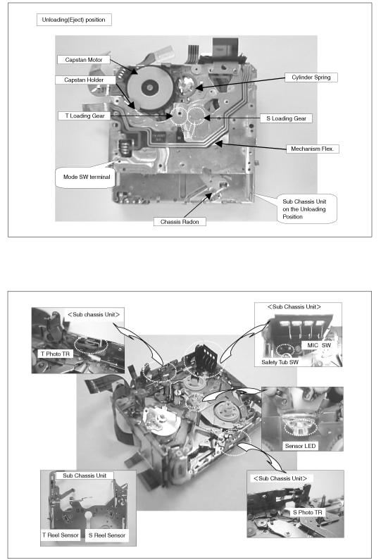
1.2 BOTTOM SIDE
1.3 SENSOR POSITION
2 SERVICING FIXTURES& TOOLS
2.1 FIXTURES& TOOLS FOR DISASSEMBLY& ASSEMBLY
No. |
Parts number |
Parts Name |
Q´ty |
New |
Remarks |
|
|
|
|
|
|
1 |
VFK1390 |
Precision Driver |
1 |
• |
|
|
|
|
|
|
|
2 |
VFK1444 |
Gear Driver |
1 |
• |
|
|
|
|
|
|
|
3 |
VFK1444Q2 |
Gear Driver for Q2 & Q3mecha. |
1 |
• |
|
|
|
|
|
|
|
4 |
VFK1650 |
Cut Washer Jig(0.86) |
1 |
• |
|
|
|
|
|
|
|
5 |
VFK1649 |
Cut Washer Jig(0.65) |
1 |
• |
|
|
|
|
|
|
|
6 |
VFK1024 |
Molytone Grease |
1 |
• |
|
|
|
|
|
|
|
2.2 FIXTURES&TOOLS FOR MECHANICAL ADJUSTMENT
No. |
Parts number |
Parts Name |
Q´ty |
New |
Remarks |
|
|
|
|
|
|
7 |
VFK1278 |
Post Adjustment Driver |
1 |
• |
|
|
|
|
|
|
|
8 |
VFK1638 |
Capstan Tilt Adj. Jig |
1 |
• |
|
|
|
|
|
|
|
9 |
VFK1641 |
Envelope Detecor Board |
1 |
• |
|
|
|
|
|
|
|
10 |
VFM3110EDS(PAL) |
DV Alignment Tape |
1 |
-- |
or VFM3010EDS(NTSC) |
|
|
|
|
|
|
11 |
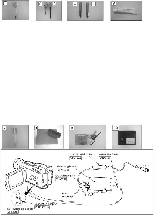
VFK1395 |
232C(M3) I/F Cable |
1 |
-- |
"TATSUJIN" system |
|
|
|
|
|
|
12 |
VFK1308E |
Measuring Board |
1 |
-- |
"TATSUJIN" system |
|
|
|
|
|
|
13 |
VFK1309 |
EVR Connecor Board |
1 |
-- |
"TATSUJIN" system |
|
|
|
|
|
|
14 |
VFK1309EX |
Connection Adaptor |
|
-- |
"TATSUJIN" system |
|
|
|
|
|
|
15 |
VFK1317 |
30pin Flat Cable |
2 |
-- |
or VFK1517(New - 300mm) |
|
|
|
|
|
"TATSUJIN" system |
16 |
VJA0941 |
DC Output Cable |
1 |
-- |
"TATSUJIN" system |
|
|
|
|
|
|

2.3MAINTENANCE FOR CAPSTAN TILT ADJUSTMENT JIG.
1.Keep applying oil for preventive oxidation on base block. Glove should be used when you apply oil.
2.Do not apply pressure to this jig.
3.If Brightness of LED become weak, Battery (SUM4 X 2) in the top of box should be changed.
4.Inspect sensor pin regularly as following.
A.Put Gage Block to sensor pin.
B.Confirm LED is lit.
If not, adjust sensor pin by rotating a screw.
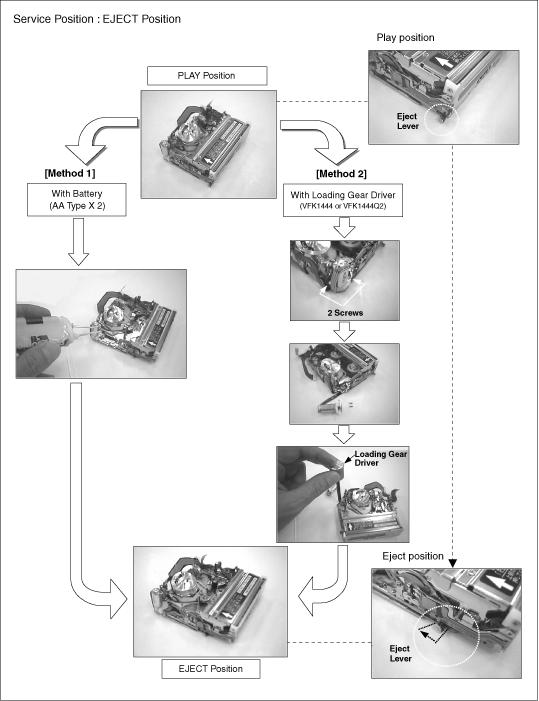
3 DISASSEMBLY PROCEDURE
3.1 PREPARATION FOR DISASSEMBLY
3.2 DISASSEMBLY PROCEDURE
No. |
Item |
Fig. |
|
Procedure |
|
|
|
|
|
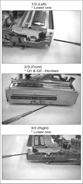
1 |
Cassette Up Unit. |
Fig. D1-1 |
1) |
Remove 3 screws. (Q1 &2 have 4 screws) |
|
|
|
|
|
|
|
Fig. D1-2 |
2) |
Take coupling portion off from both S &T sides. |
|
|
|
|
|
*2 |
H Amp Unit. |
Fig. D2-1 |
1) |
Remove a screw from Shield case. |
|
(Only Q1 & Q2) |
|
|
|
|
Fig. D2-2 |
2) |
Take Cylinder Flex. From connector. |
|
|
|
|||
|
|
|
|
|
|
|
Fig. D2-3 |
3) Remove a screw from H Amp Angle. |
|
|
|
|
|
|
3 |
Cylinder Unit & RT Flex. Flame. |
Fig. D3-1 |
1) |
Remove a screw from RT Flex. Flame. |
|
|
|
|
|
|
|
Fig. D3-2 |
2) |
Remove 3 screws and then take Cylinder Spring out. |
|
|
|
|
|
|
|
Fig. D3-3 |
3) |
Remove a screw and take RT Flex. Flame out. |
|
|
|
|
|
4 |
LED Holder, Cover plate & Idler U. |
Fig. D4-1 |
1) |
Pull up and remove LED Holder. |
|
|
|
|
|
|
|
Fig. D4-2 |
2) |
Move LED Flat Cable out of position and unhook 2 springs. |
|
|
|
|
|
|
|
Fig. D4-3 |
3) |
Remove 5 screws and remove Cover Plate & Idler U. |
|
|
|
|
|
5 |
Sub Chassis Unit |
Fig. D5-1 |
1) |
Remove 4 screws. |
|
|
|
|
|
|
|
Fig. D5-2 |
2) |
Remove a screw and unhook a spring from Pinch Arm. |
|
|
|
|
|
6 |
Pinch Arm & Center Gear |
Fig. D6-1 |
1) |
Remove Cut Washer and take Pinch Arm out. |
|
|
|
2) |
Take Center Gear out. |
|
|
|
|
|
|
|
Fig. D6-2 |
3) |
Take Center Gear Spacer out. |
|
|
|
|
|
7 |
Rail Unit |
Fig. D7-1 |
1) |
Make half loading until |
|
|
|
|
Connection Arm comes out. |
|
|
Fig. D7-2 |
2) |
Disconnect Connection Arms. |
|
|
|
|
a) Hold Loading Gear side. |
|
|
|
|
b) Disconnect connection arms. |
|
|
|
|
|
|
|
Fig. D7-3 |
3) |
Remove 4 screws. |
|
|
|
|
|
8 |
T-Loading Gear & S-Loading Gear |
Fig. D8 |
1) |
Take T-Loading Gear out. |
|
|
|
2) |
Remove Cut Washer on S-Loading Gear and take S-Loading Gear out. |
|
|
|
* Removed Cut Washer can not be used again. |
|
|
|
|
|
|
9 |
Gear Cover |
Fig. D9 |
1) |
Remove a screw and slide Gear Cover to take out. |
|
|
|
|
|
10 |
Pinch Beetle & Release Beetle |
Fig. D10 |
1) |
Remove a washer and take Pinch Beetle and Release Beetle out together. |
|
|
|
|
|
11 |
Tension Lever & Eject Arm. |
Fig. D11 |
1) |
Remove a screw and take Tension Lever out. |
|
|
|
2) |
Remove a washer and take Eject Arm out. |
|
|
|
|
|
12 |
Interface Gears |
Fig. D12 |
1) |
Remove 4 Gears. |
|
|
|
|
|
13 |
Cam Gear |
Fig. D13 |
1) Remove Cam Gear. |
|
|
|
|
|
|
14 |
Chassis Radon |
Fig. D14 |
1) |
Remove a washer. |
|
|
|
|
|
15 |
Boat Radon |
Fig. D15 |
1) |
Remove Boat radon. |
|
|
|
|
|
16 |
Drive Gear |
Fig. D16 |
1) |
Remove Drive Gear and a White Waher underneath. |
|
|
|
|
|
17 |
Capstan Holder & Capstan Motor |
Fig. D17- |
1) |
Remove 2 screws and take Capstan Holder out. |
|
|
1 |
* It is not necessary to remove 2 screws for New Capstan Holder. Because it |
|
|
|
|
shapes screw. |
|
|
|
|
|
|
|
|
Fig. D17- |
2) Remove 3 screws and take Capstan Motor out downword. |
|
|
|
2 |
|
|
|
|
|
|
|
18 |
Loading Motor unit & Mechanism Interface |
Fig. D18- |
1) |
Remove 2 screws and take Loading Motor Unit out. |
|
Flex. |
1 |
|
|
|
|
|
|
|
|
|
Fig. D18- |
2) Remove 4 screws and dissolder at Mode Sw. |
|
|
|
2 |
|
|
|
|
|
|
|
*19 |
Mode Switch , Deceleration Gears & Tension |
Fig. D19 |
1) |
Take Mode Sw out. |
|
Plate. |
|
2) |
Remove a washer and take Deceleration Gear (A) out. |
|
|
|
3) |
Take Deceleration Gear (B) out |
|
|
|
4) |
Remove 2 washers and take Tension Plate. |
|
|
|
|
|
*20 |
T4 Guide , Eject Lever , Pulley Cover & |
Fig. D20- |
1) Remove a screw and take T4 Guide out. |
|
|
Pulley. |
1 |
|
|
|
|
|
|
|
|
|
Fig. D20- |
2) Remove a washer and take Eject Lever out. |
|
|
|
2 |
|
|
|
|
|
|
|
|
|
Fig. D20- |
3) Remove 2 screw and take Pulley Cover out. |
|
|
|
3 |
4) |
Take Pulley out. |
|
|
|
|
|
*21 |
S3 Base U. |
Fig. D21 |
1) Remove a screw for S3 adjustment and take S3 Base U. |
|
|
|
|
|
|
* 1) Procedure 2 for H.Amp Unit is applied only Q1 & Q2 mechanism.
2) Procedure 19 - 21 can be changed in order.
Fig. D1-1
Fig. D1-2
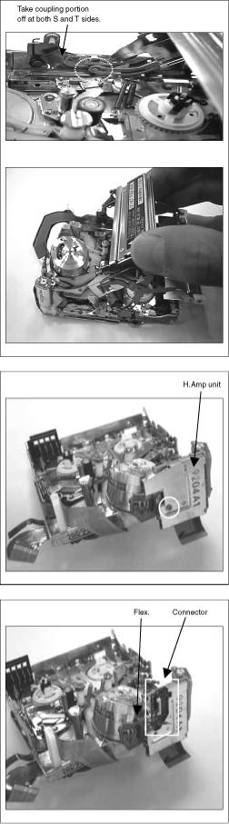
Fig. D2-1
Fig. D2-2
Fig. D2-3
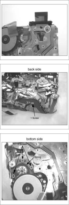
Fig. D3-1
Fig. D3-2
Fig. D3-3
Fig. D4-1
Fig. D4-2
Fig. D4-3
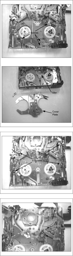
Fig. D5-1
Fig. D5-2
Fig. D6-1
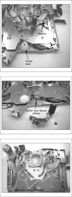
Fig. D6-2
Fig. D7-1
Fig. D7-2
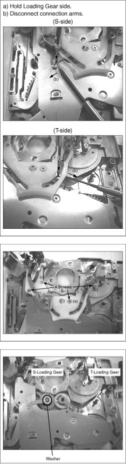
Fig. D7-3
Fig. D8
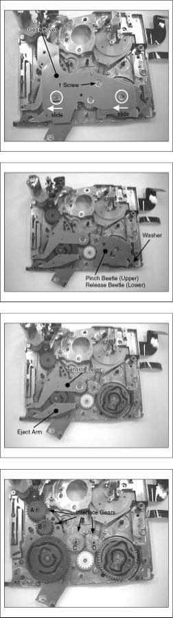
Fig. D9
Fig. D10
Fig. D11
Fig. D12
Fig. D13
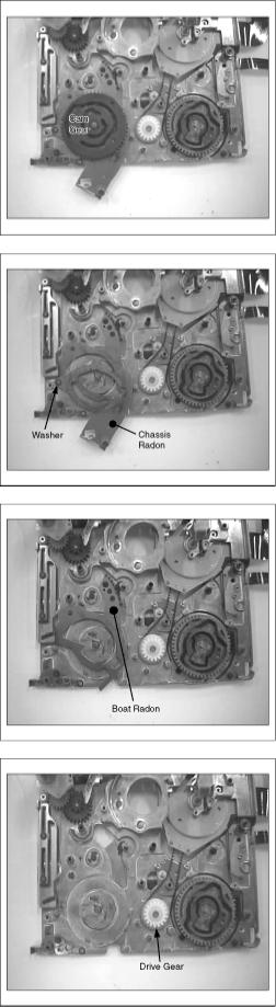
Fig. D14
Fig. D15
Fig. D16
Fig. D17-1
 Loading...