


 Loading...
Camera Control Unit
GP-KS162CUDE
(Lens, Cable and Camera Head : option)
Before attempting to connect or operate this product, please read these instructions completely
ENGLISH
DEUTSCH
FRANÇAIS
ENGLISH VERSION
CONTENTS |
|
PREFACE .............................................................................................................................................................................................. |
1 |
FEATURES ............................................................................................................................................................................................ |
1 |
PRECAUTIONS ..................................................................................................................................................................................... |
2 |
SYSTEM BLOCK DIAGRAM ................................................................................................................................................................. |
3 |
MAJOR OPERATING CONTROLS AND THEIR FUNCTIONS .............................................................................................................. |
3 |
PREPARATIONS ................................................................................................................................................................................... |
6 |
SPECIFICATIONS ................................................................................................................................................................................ |
7 |
OPTIONAL ACCESSORIES .................................................................................................................................................................. |
7 |
CAUTION:
Before attempting to connect or operate this product, please read the label on the bottom.
CAUTION
RISK OF ELECTRIC SHOCK
DO NOT OPEN
CAUTION:
TO REDUCE THE RISK OF ELECTRIC SHOCK, DO NOT REMOVE COVER (OR BACK), NO USER SERVICEABLE PARTS INSIDE.
REFER SERVICING TO QUALIFIED SERVICE
PERSONNEL.
The lighthing flash with arrowhead symbol, within an equilateral triangle, is interned to alert the user to the presence of uninsulated "dangerous voltage" within the product's enclosure that may be of sufficient magnitude to constitute a risk of electric shock to persons.
The exclamation point within an equilateral triangle is intended to alert the user to the presence of important operating and maintenance (servicing) instructions in the literature accom-panying the appliance.
This model conforms of the EC directive (for radio interference) 87/308/EEC.
This apparatus was produced to BS 800:1987.
Dit model is onderworpen aan de EEG-richtlijn (ter voorkoming van radio-interferentie) 87/308/EGG.
Denne model opfylder EF direktiv 87/308/EF (for forebyggelse af radiointerferens).
Este modelo cumple con la norma EC (para interferencias de radio 87/308/EEC).
La Società PANASONIC ITALIA S.p.A., importatrice di questo prodotto, dichiara che questo apprarecchio è conforme alle disposizioni della direttiva C.E.E./87/308 (D.M. 13 aprile 1989).
The serial number of this product may be found on the bottom of the unit.
You should note the serial number of this unit in the space provided and retain this book as a permanent record of your purchase to aid identification in the event of theft.
Model No.
Serial No.
WARNING:
TO PREVENT FIRE OR SHOCK HAZARD, DO NOT EXPOSE THIS APPLIANCE TO RAIN OR MOISTURE.

PREFACE
The Panasonic Camera Control Unit GP-KS162CU is designed to use with the optional Camera Head GPKS162H.
This system overcomes space limitations that have complicated many video applications. Weight of only 16g (0.04 lbs.), this remarkably compact CCTV camera measures only two-thirds of an inch in diameter and less than two inches in length. GP-KS162CU Remote Control Unit (CCU) and optional camera head GP-KS162H can be extended up to 10-meter (33 feet) away, using an optional 10-meter (33-feet) cable. So the exceptionally manuerable GP-KS162 series lets you obtain a whole new world of camera angles and shots that were once quite difficult to achieve. With the 440,000-element, 1/2-inch CCD pick-up device, horizontal resolution is more than 480 lines, and signal-to-noise ratio is 50 dB. An Auto Light Selection Switch and lets you obtain clear, high-quality colour images in light as low as 3 lux at F1.4.
In addition, a small diameter wide-angle lens developed by Matsushita makes high resolution standard even with subjects as close as 4/5th of an inch away.
Colour changes are sensed instantly and compensated for by a microcomputer in the GP-KS162CU. Proper white balance is then obtained via the built-in-Auto Tracing White Balance (ATW) circuit. Both White Balance and R and B colour can also be adjusted manually, for optimum colour reproduction.
The camera head can be used with most existing camera systems. And VTR, video printer or floppy disk recorder, for a host of new and traditional applications.
FEATURES (With GP-KS162H)
1.1/2 inch Interline CCD image sensor with 752 (H) x 582
(V) pixels.
2.480 lines of horizontal resolution.
3.3 lux at F1.4 of minimum scene illumination.
4.50 dB of signal to noise ratio.
5.Selectable Through the Lens Auto Tracing White Balance (ATW), Auto White Balance Control (AWC) or Manual White Balance Control.
6.Auto Light Control Switch enables to control the video output level to constant level whatever the object brightness may be.
7.Video Level Control enables to adjust the video level to your preference.
8.The preset 1, preset 2 and automatic setting mode are provided for Back Light Compensation (BLC) function.
9.2-memory AWC mode is available.
10.DC 12V operation
11.10-meter (33-feet) of maximum cable length between camera head and camera control unit with optional camera cable.
12.S-VHS Video Output is provided.
ENGLISH
The model numbers listed in this Operating Instructions have no suffixed attached to it.
-1-

PRECAUTIONS
•Do not attempt to disassemble the camera.
To prevent electric shock, do not remove screws or cover. There are no user-serviceable parts inside. Refer servicing to qualified service personnel.
•Do not expose the camera or camera control unit to rain or moisture, or do not try to operate it in wet areas. Do take immediate action if ever the camera or camera control unit do become wet. Turn power off and refer servicing to qualified service personnel.
Moisture can damage the camera and camera control unit and also create the danger of electric shock.
•Ambient Temperature range
Do not install the camera in the place which is beyond −10°C - +50 °C (14 °F - 122 °F).
•Do not drop anything inside the camera.
Dropping metal for example inside the camera could permanently damage the unit.
•Never crush or pinch the camera cable.
Do not bend the camera cable into a curve whose radius is too small.
•Never face the camera toward the sun.
Whether the camera is in use or not, never face it toward the sun.
Do use caution when operating the camera in the vicinity of spot lights or other lights and light reflecting objects.
•How to take care of this camera.
After turning OFF the Power ON/OFF Switch, clean it with a dry cloth. If it is difficult to remove the dirt or dust, clean it up with a cloth applied the neutral cleanser.
Use the lens cleaning tissue paper (may be available at your local camera store) for lens cleaning.
•Connect this to a DC12V, 0.5 A - 0.7 A CLASS 2 Power supply only.
•After using the camera, turn OFF the power ON/OFF Switch and put the lens cap on the camera head.
•Every necessary procedures with regard to install this product should be made by qualified service personnel or system installers.
Caution:
Connecting or disconnecting camera cable to/from the camera control unit must be done after turning OFF the Power ON/OFF Switch. Otherwise, the camera head may be damaged.
-2-

SYSTEM BLOCK DIAGRAM
GP-KS162 Series Standard Configuration |
|
|
|
|
|
|
|
|
|
|||||||||||||
Camera Head, Camera Control Unit. |
|
|
|
|
|
|
|
|
|
|||||||||||||
|
|
|
|
|
|
|
Optional |
|
||||||||||||||
|
|
|
|
|
|
|
|
|
|
|
|
|
|
|
|
|
|
|
|
|
|
|
|
|
|
|
|
|
|
|
|
|
|
|
|
|
|
|
|
|
|
|
|
Camera Cable |
|
|
|
|
|
|
|
|
|
|
|
|
|
|
|
|
|
|
|
|
|
|
GP-CA162/2: 2m |
|
|
|
|
|
|
|
|
|
|
|
|
|
|
|
|
|
|
|
|
|
|
GP-CA162/3: 3m |
|
|
|
|
|
|
|
|
|
|
|
|
|
|
|
|
|
|
|
|
|
|
GP-CA162/38: 3.8m |
|
|
|
|
|
|
|
|
|
|
|
|
|
|
|
|
|
Panasonic |
GP-KS162H |
|
|
|
GP-CA162/10: 10m |
|
|
|
|
|
|
|
|
|
|
|
|
|
K |
|
|
|
|
|
|
|
|
||
|
|
|
|
|
|
|
|
|
|
|
|
C |
|
|
|
|
|
|
|
|
||
|
|
|
|
|
|
|
|
|
|
|
|
O |
|
|
|
|
|
|
|
|
||
|
|
|
|
|
|
|
|
|
|
|
|
L |
|
|
|
|
|
|
|
|
||
|
|
|
|
|
|
|
|
|
|
|
|
S |
|
|
|
|
|
|
|
|
||
|
|
|
|
|
|
|
|
|
|
|
|
U |
|
|
|
|
|
|
|
|
||
|
|
|
|
|
|
|
|
|
|
|
|
C |
|
|
|
|
|
|
|
|
||
|
|
|
|
|
|
|
|
|
|
|
|
O |
|
|
|
|
|
|
|
|
||
|
|
|
|
|
|
|
|
|
|
|
|
F |
|
|
|
|
|
|
|
|
||
|
|
|
|
|
|
|
|
|
|
|
|
|
|
|
|
|
|
|
|
|
||
|
Optional Camera Head |
|||||||||||||||||||||
|
(GP-KS162H) |
|
|
|
|
|
|
|||||||||||||||
Optional Accessories |
|
|
|
|
|
|
|
|
|
|
|
|
|
|
|
|
|
|
|
|||
Wide Angle Lens |
|
|
|
|
|
|
|
|
|
|
|
|
|
|
|
|
|
|
Wide Angle Lens |
|||
|
|
|
|
|
|
|
|
|
||||||||||||||
GP-LM3TA |
|
|
|
|
|
|
|
|
|
|
|
|
|
|
|
|
|
|
GP-LM7TA |
|||
Pinhole Lens |
|
|
|
|
|
|
|
|
|
|
|
|
|
|
|
|
|
Tele Angle Lens |
||||
|
|
|
|
|
|
|
|
|
|
|
|
|
|
|
|
|
|
|||||
GP-LP12TA |
|
|
|
|
|
|
|
|
|
|
|
|
|
|
|
|
GP-LM15TA |
|||||
C-Mount Adaptor |
|
|
|
|
|
|
|
|
|
|
|
|
|
|
|
|
Tele Angle Lens |
|||||
|
|
|
|
|
|
|
|
|
|
|
|
|
|
|
|
|
|
|
||||
GP-AD22TA |
|
|
|
|
|
|
|
|
|
|
|
|
|
|
|
|
GP-LM24TA |
|||||
|
WHITE |
AUTO |
VIDEO |
|
DC POWER |
BAL |
LIGHT |
LEVEL |
CAMERA |
|
AWC |
ON |
MANU |
|
ON |
ATW |
|
||
OFF |
OFF |
|
||
MANU |
|
|||
OFF |
AWC SET |
|
|
GP- KS162 |
|
R |
B |
LEVEL |
|
Camera Control Unit GP-KS162CU
MAJOR OPERATING CONTROLS AND THEIR FUNCTIONS
Camera Control Unit GP-KS162CU
q |
w e r |
y |
u |
o |
!4!6!8@0 |
!2 !0 |
|
|
|
|
|
!5!7!9@1 |
|
|
WHITE |
AUTO |
VIDEO |
|
|
S-VIDEO OUT |
DC POWER |
BAL |
LIGHT |
LEVEL |
CAMERA |
|
|
|
AWC |
ON |
MANU |
|
ON |
ATW |
|||
OFF |
OFF |
|||
MANU |
||||
|
|
|
DC 12V IN |
|
|
|
|
VIDEO |
VIDEO |
|
AWC SET |
|
|
OUT 1 |
OUT 2 |
OFF |
|
GP- KS162 |
|
||
|
|
|
|
|
|
|
R |
B LEVEL |
|
|
|
|
t |
i |
|
!3 |
!1 |
Optional Camera Head GP-KS162H with Optional Lens GP-LM7TA |
|
||||
|
#1 |
|
#2 |
#3 |
|
LOCKFOCUS


 Panasonic
GP-KS162H
-3-

Camera Control Unit GP-KS162CU
1.DC Power On/Off Switch (DC POWER, ON/OFF)
2.Auto White Balance Control Button (AWC SET)
The white balance can be set by pressing this button when the White Balance Selection Switch (4) is set to the AWC position.
3.White Balance Indicator
4.White Balance Selection Switch (WHITE BAL, AWC/ATW/MANU)
AWC : The white balance is automatically set and fixed by detecting the characteristic / colour temperature of light source through the lens and controlling the gain of red and blue signal. The White Balance Indicator lights during the setting.
Note: When the White Balance Offset On/Off Switch is turned on, the fine adjustment for R/B gain is available by means of the R and B Gain Controls (5) after completing the white balance setting. The adjustable range is approx. 2,200K - 10,000K.
ATW : The white balance is automatically and continuously set by detecting the characteristic / colour temperature of light source through the lens and controlling the gain of red and blue signal even if the characteristic / colour temperature varies.
Note: When the White Balance Offset On/Off Switch is turned on, the fine adjustment for R/B gain is available by means of the R and B Gain Controls after completing the white balance setting. The adjustable range is approx. 2,300K - 6,000K.
MANU: The R/B gain of the white balance can be adjusted manually by means of the R and B Gain Controls.
The adjustable range of the white balance temperature is approx. 2,200K - 10,000K.
5.R / B Gain Controls (R/B)
These controls are used to adjust the R and B gain of the white balance.
6.Auto Light On/Off Switch (AUTO LIGHT ON/OFF) ON: When this switch is set to the ON position, the
video signal is set to the best level with the combination of the Electronic light Control On/Off Switch
(14)and AGC On/Off Switch (15).
7.Video Level Selection Switch (VIDEO LEVEL, MANU/OFF)
This switch is used to select the Video Level.
OFF: When this switch is set to the OFF position, the video signal is supplied with the standard level.
MANU: When this switch is set to the MANU position, the video level is adjustable by means of the Video Level Control (8).
Note: This switch can be used as the Gain Up/Down Switch due to the value set by the Video Level Control (8).
8.Video Level Control (LEVEL)
This controls the video level when the Video Level Selection Switch (7) is set to the MANU position.
The video level control depends on the Auto Light On/Off Switch (6) setting as shown below.
AUTO LIGHT OFF :
By turning this counterclockwise, the video level is decreased.
By turning this clockwise, the video level is increased.
The video level setting at the centre position of this control is higher than the standard one.
AUTO LIGHT ON :
By turning this counterclockwise, the standard video level is decreased.
By turning this clockwise, the standard video level is increased.
The standard video level setting at the centre position of this control is higher than standard one.
9.Camera Cable Connector (CAMERA)
This 16-pin connector is used for connection of the optional camera cable.
Caution: Connecting or disconnecting the camera cable must be done after turning OFF the Power ON/OFF Switch.
10.S-Video Output Connector (S-VIDEO OUT)
The luminance (Y) and chroma (C) signals for S-VHS VTR or monitor are provided at this connector.
Pin Configuration
4 |
3 |
2 |
1 |
Pin No. |
Description |
|
|
1. |
Y Ground |
2. |
C Ground |
3. |
Y Signal Output: 0.7 Vp-p (Y level/75 ohms) |
4. |
C Signal Output: 0.3 Vp-p (burst Level/75 ohms) |
|
|
11.EVR Adjustment Connector
This connector is used to connect with the EVR.
12.Video Output Connectors (BNC) (VIDEO OUT 1,2)
A 1.0 Vp-p ohms composite video signal is provided at this connector.
13.DC 12V Input Terminals (DC 12V IN)
These terminals accept an external DC source supplying nominal power of 12V, 0.5A - 0.7A.
CAUTION: CONNECT THIS TO A DC 12V CLASS 2 POWER SUPPLY ONLY.
-4-
14. Electronic Light Control (ELC) On/Off Switch |
|
on |
|
off |
When shooting the objects under the high light condition, the lighting can be controlled by the electronic shutter mode.
This switch is used to disable the ELC function. Normally turn on this switch.
15. AGC On/Off Switch |
|
on |
|
off |
When shooting the objects under the low light condition, the video level can be controlled by the gain of the video amplifier.
This switch is used to disable the AGC function. Normally, turn on this switch.
In the Auto Light On mode, the setting mode is different by the combination of ELC On/Off switch (14) and AGC On/Off switch (15) as shown below.
|
|
ELC On/Off Switch (14) |
|||||
|
|
|
|
|
|
|
|
|
|
On |
|
|
|
Off |
|
|
|
|
|
|
|
|
|
AGC On/Off |
On |
ELC On |
|
|
ELC Off |
||
AGC On |
|
|
AGC On |
||||
Switch (15) |
|
|
|
||||
|
|
|
|
|
|
|
|
Off |
ELC |
On |
|
Auto Light Function |
|||
|
|
||||||
|
AGC |
Off |
|
is disable |
|||
|
|
|
|||||
|
|
|
|
|
|
|
|
16. White Balance Offset On/Off Switch |
|
|
on |
||||
|
|
off |
|||||
|
|
||||||
By turning on this switch, the white offset in the AWC/ATW can be adjusted fine by using the R/B Gain Controls (5).
Usually, turn off this switch.
17. 2-Memory AWC Mode On/Off Switch |
|
on |
|
off |
By turning on this switch, the two kinds of white balance can be memorized.
The function of the White Balance Selection Switch is changed as shown below by turning on this switch.
WHITE
BAL By turning on this switch
AWC |
|
ATW |
|
MANU |
|
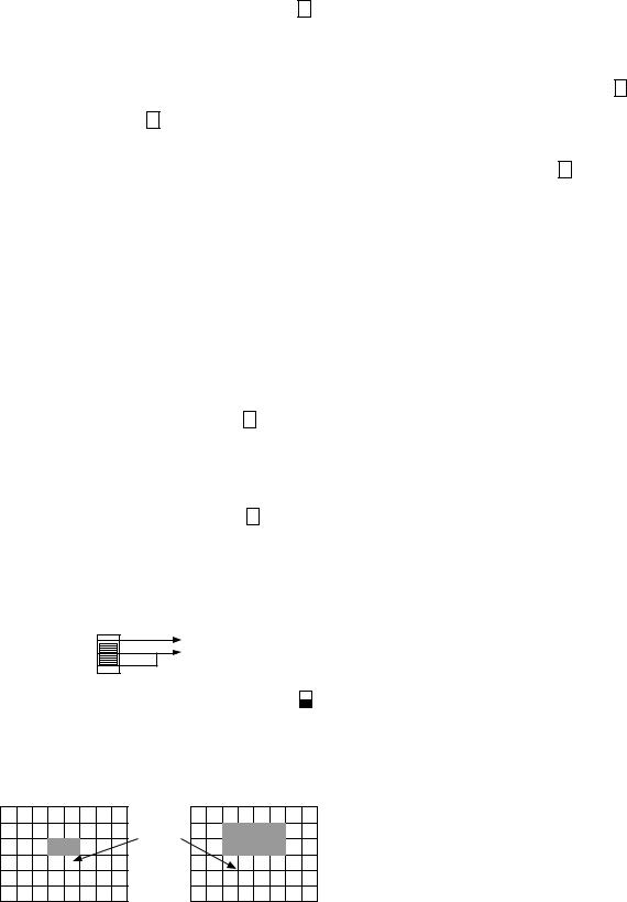
18/19. Back Light Control (BLC) Mode Selection Switch |
on |
off |
The back light sensing zone can be set in the Auto Light On mode.
00: BLC OFF (All of the screen)
01: BLC Preset 1 (Pattern 1 Sensing Zone) 10: BLC Preset 2 (Pattern 2 Sensing Zone)
Sensing
Zone
|
|
|
|
|
|
|
|
BLC Preset 1 |
BLC Preset 2 |
||
11:Automatic Sensing Zone
The Automatic Sensing Zone setting works effectively against the optical shading around the screen in an optical instrument use.
In this case, this camera sets the sensing zone automatically when the AWC has been set with the white objects.
This function is invalided by setting the white balance again.
In the AWC mode, the Automatic Sensing Zone setting is available.
on
20.Aperture Level Selection Switch  off
off
The aperture level can be selected by this switch. High level can be obtained by turning on this switch. Low level can be obtained by turning off this switch.
21. Cable Selection Switch |
|
on |
|
off |
This switch is provided for optional cable GPCA162/38 and GP-CA162/10.
CAUTION: BE SURE TO TURN ON THIS SWITCH BEFORE TURNING ON THE POWER.
When using the optional cable GP-CA162/2 and GPCA162/3, turn off this switch.
Optional Camera Head GP-KS162H with Optional Lens GP-LM7TA
31.Manual Iris Control Ring
This ring is used to adjust the lens iris manually.
32.Focus Ring
This ring is used to adjust the focus of the picture. To adjust the focus, loosen the Focus Lock Ring (33) by rotating it clockwise (viewed from the front of the camera) and turn the Focus Ring until picture becomes the best resolution. Secure the Focus Ring by rotating the Focus Lock Ring (33) counterclockwise.
33.Focus Lock Ring
This ring is used to secure the Focus Ring.
-5-

PREPARATIONS
Caution: Keep the Power ON/OFF Switch of the camera in the OFF position through the installation.
GP-KS162H with GP-LM3TA, GP-LM7TA, GP-LM15TA, GP-LM24TA or GP-LP12TA
1.Remove the front cap of the camera and confirm that the surface of the optical filter of the camera head is clean.
Front Cap
If the surface of the optical filter is dirty or dusts are on it, clean it up with a blower brush which is for film camera lenses (may be available at your local camera store) or supplied lens cleaning tissue paper.
2.Rotate the focus lock ring fully clockwise.
Mount the Pinhole Lens, Wide-angle Lens or Super Wide-angle Lens to the camera by rotating it clockwise slowly.
Focus Lock Ring
GP-KS162H with GP-AD22TA and optional C-mount lens
1.Remove the front cap of the camera head and confirm that the surface of the optical filter of the camera head is clean.
Front Cap
If the surface of the optical filter is dirty or dusts are on it, clean it up with a blower brush which is for film camera lenses (may be available at your local camera store) or supplied lens cleaning paper.
2.Attach the optional C-mount lens to the C-mount Adaptor GP-AD22TA by rotating it clockwise.
3.Rotate the focus lock ring fully clockwise.
Mount the lens and C-mount adaptor by rotating them clockwise slowly.
Focus Lock Ring
Caution: If the optional C-mount lens size exceeds 2” (50.8 mm) in diameter, 2-3/4” (70 mm) in length and 0.66 lbs. (300g) in weight, both the camera and lens should be secured.
-6-
SPECIFICATIONS (with the combination of Optional Camera Head GP-KS162H)
Pick-up Device : |
1/2-inch Interline transfer CCD image sensor with 752 (H) x 582 (V) pixels |
|
Horizontal Resolution : |
480 lines |
|
Minimum Scene Illumination : |
3 lux (F1.4 with AGC ON more than 30% of Y signal with set up) |
|
|
5 lux (F1.6 with AGC ON more than 30% of Y signal with set up) |
|
Signal to Noise Ratio : |
50 dB (Standard condition, Y signal) |
|
Video Output : |
1.0 Vp-p/75 ohms, composite video, BNC connector x 2 |
|
Scanning System : |
2:1 Interlace |
|
Synchronization : |
Internal Sync only |
|
White Balance : |
Auto Tracing White Balance (ATW)/Auto White Balance Control (AWC)/Manual (MANU) |
|
Gain Control : |
Auto Light On/Off, Video Level (Off/Manual) |
|
Switches : |
White Balance Mode (ATW/MANU/AWC), AWC SET (SET), Auto Light, |
|
|
Video Level (Off/Manual) |
|
Controls : |
R, B gain, VIDEO Level |
|
Power Source : |
12V DC, 300 mA |
|
Camera Cable Length : |
GP-CA162/2 Cable 2-meter (6.6 feet), GP-CA162/3 Cable 3-meter (9.9 feet), |
|
|
GP-CA162/38 Cable 3.8-meter (12.5 feet), GP-CA162/10 Cable 10-meter (33 feet) |
|
Ambient Temperature : |
−10°C - +50°C (14°F - 104°F) |
|
Dimensions : |
Camera Control Unit : 120 (W) x 36 (H) x 157 (D) mm |
|
|
|
4-11/16” (W) x 1-7/16” (H) x 6-1/8” (D) |
|
Camera Head : |
17 (Diameter) x 35.5 (D) mm, (2/3” (Diameter) x 1-1/2”(D)) |
Weight : |
Camera Control Unit : 550 g (1.2 lbs.) |
|
|
Camera Head : |
14 g (0.035 lbs.) |
Weight and dimensions indicated are approximate.
Specifications are subject to change without notice.
Optional Accessories
•Camera Cable GP-CA162/2, GP-CA162/3, GP-CA162/38 or GP-CA162/10
•C-mount Adaptor GP-AD22TA
•Wide Angle Lens GP-LM3TA or GP-LM7TA
•Pinhole Lens GP-LP12TA
•Tele Angle Lens GP-LM15TA or GP-LM24TA
•Camera Head GP-KS162H
-7-
Loading...