


|
|
|
|
|
|
|
|
|
|
|
|
|
|
|
|
|
|
|
|
|
|
|
|
|
|
|
|
|
|
|
|
|
|
|
|
|
|
|
|
|
|
|
|
|
|
|
|
|
|
Indoor Pan/Tilt Head |
AW-PH400 |
||||
|
Pan/Tilt Head Controller |
AW-RP400E |
||||
|
Cable Compensator |
AW-RC400E |
||||
|
Roll Unit |
AW-RL400G |
||||
AW-PH400 |
AW-RP400 |
AW-RC400 |
AW-RL400 |
|
|
|
|
|
|
|
|
|
|
|
|
|
ENGLISH
DEUTSCH
FRANÇAIS
ITALIANO
ESPAÑOL
Before attempting to connect, operate or adjust this product, please read these instructions completely.

ENGLISH VERSION
Safety precautions
$ DO NOT REMOVE PANEL COVER BY
UNSCREWING.
To reduce the risk of electric shock, do not remove cover. No user serviceable parts inside.
Refer servicing to qualified service personnel.
WARNING:
TO REDUCE THE RISK OF FIRE OR SHOCK HAZARD, KEEP THIS EQUIPMENT AWAY FROM ALL LIQUIDS-USE AND STORE ONLY IN LOCATIONS WHICH ARE NOT EXPOSED TO THE RISK OF DRIPPING OR SPLASHING LIQUIDS, AND DO NOT PLACE ANY LIQUID CONTAINERS ON TOP OF THE EQUIPMENT.
CAUTION:
TO REDUCE THE RISK OF FIRE OR SHOCK
HAZARD AND ANNOYING INTERFERENCE,
USE THE RECOMMENDED ACCESSORIES
ONLY.
1 indicates safety information.
1 (E)

Contents
Safety precautions ........................................................... |
1 |
Precautions for use .......................................................... |
3 |
AW-PH400 Indoor Pan/Tilt Head ................................. |
4 |
Introduction ...................................................................... |
4 |
Accessories ...................................................................... |
4 |
Precautions for use .......................................................... |
4 |
Installation precautions ................................................... |
5 |
Parts and their function ................................................... |
6 |
Installation ...................................................................... |
10 |
$ Assembling the pan/tilt head .................................... |
10 |
$ Setting the mounting direction switch ...................... |
11 |
$ Setting the PCB switches ......................................... |
12 |
$ Changing the mounting position of |
|
the pedestal connector panel .............................. |
13 |
$ Installing the pan/tilt head ........................................ |
14 |
$ Mounting the camera ............................................... |
15 |
$ Attaching the chain .................................................. |
16 |
Replacing the consumable parts .................................. |
17 |
Specifications ................................................................. |
18 |
AW-RC400 Cable Compensator ................................. |
35 |
Introduction .................................................................... |
35 |
Accessories .................................................................... |
35 |
Parts and their function ................................................. |
36 |
Example of rack mounting ............................................ |
38 |
$ How to mount the AW-RC400 in a rack ................... |
38 |
Specifications ................................................................. |
39 |
AW-RP400 Pan/Tilt Head Controller .......................... |
19 |
Introduction .................................................................... |
19 |
Accessories .................................................................... |
19 |
Parts and their function ................................................. |
20 |
$ Front panel ............................................................... |
20 |
$ Rear panel ............................................................... |
23 |
Menu settings ................................................................. |
25 |
$ Operation method .................................................... |
25 |
$ List of menu items and settings ............................... |
26 |
Example of rack mounting ............................................ |
30 |
$ How to mount the AW-RP400 in a rack ................... |
30 |
$ How to change the direction of the connector panel ... |
31 |
$ How to replace the zoom switch .............................. |
32 |
Replacing the consumable parts .................................. |
33 |
Specifications ................................................................. |
34 |
AW-RL400 Roll Unit .................................................... |
41 |
Introduction .................................................................... |
41 |
Accessories .................................................................... |
41 |
Parts and their function ................................................. |
42 |
Installation ...................................................................... |
43 |
Specifications ................................................................. |
44 |
Connections ................................................................... |
45 |
Example of system configuration ................................. |
47 |
Operating procedures .................................................... |
48 |
ENGLISH
2 (E)

Precautions for use
≥ Handle the ROP carefully.
Dropping the ROP or subjecting it to strong impact may give rise to malfunctioning or accidents.
≥ Use the ROP in an ambient temperature of –10°C to +45°C.
Using the ROP in cold places below –10°C or hot places above 45°C may adversely affect its internal parts.
≥ Turn off the power before connecting or disconnecting the cables.
Be absolutely sure to turn off the power before connecting or disconnecting the cables.
≥Avoid using the units outdoors.
≥Maintenance
Wipe the ROP using a dry cloth. To remove stubborn dirt, dip a cloth into a diluted solution of kitchen detergent, wring it out well, and wipe the ROP gently.
<Caution>
≥Avoid using benzine, paint thinners and other volatile fluids.
≥If a chemical cleaning cloth is to be used, carefully read through the precautions for its use.
3 (E)
Indoor Pan/Tilt Head AW-PH400
Introduction
≥The stand-alone compact pan/tilt head can be rotated through 190 degrees in the vertical direction and 400 degrees in the horizontal direction.
≥Operations can be performed at high speeds of up to 90 degrees per second.
≥Equipment such as a camera and lens with a total weight of 8 kg can be mounted on the unit.
≥The camera can also be rotated using the AW-RL400 roll unit available as an option.
≥The shooting positions and settings for up to 50 positions can be registered as preset memory data.
NOTE
≥The AW-PH400 cannot be controlled from the AW-RP301, AW-RP305, AW-RP501, AW-RP505, AW-RP605 or AW-RP605A controller.
≥In order to protect the environment when the pan/tilt head is to be discarded at the end of its service life, ask a specialized contractor to dispose of it properly.
ENGLISH
Accessories |
|
Rotary arm ..................................................................................................... |
1 |
Camera mounting base ................................................................................ |
1 |
Rotary arm and camera base mounting screws (with flat washers) |
|
M5!20 mm ............................................................................. |
7 |
Camera cable ................................................................................................. |
1 |
Tally lamp ....................................................................................................... |
1 |
Chain mounting screws (with flat washers, spring washers) |
|
M4!8 mm ............................................................................... |
1 |
M4!6 mm ............................................................................... |
1 |
Hexagon key wrench .................................................................................... |
1 |
AC cable ......................................................................................................... |
1 |
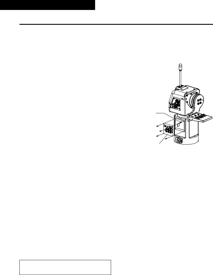
Precautions for use
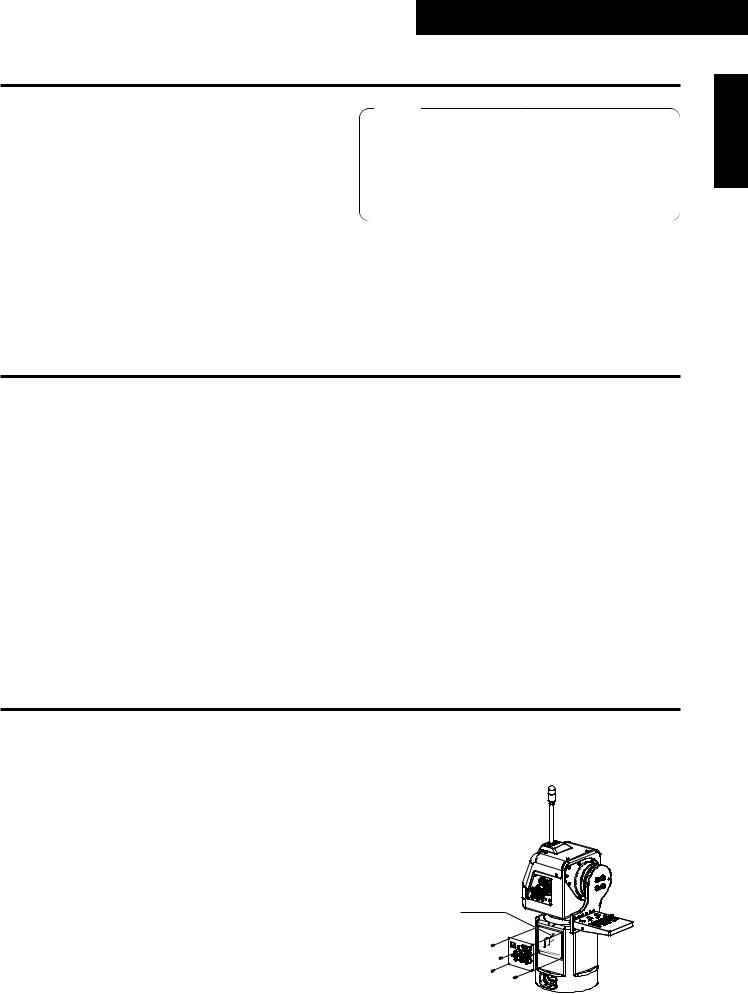
The AW-PH400 uses a manganese dioxide-lithium battery (CR2032).
Before discarding the pan/tilt head or its printed circuit boards, be absolutely sure to remove the battery.
Be absolutely sure to dispose of the removed battery in accordance with the applicable domestic laws and regulations.
Do not throw out the battery along with the general household garbage.
For the procedure to remove the battery, refer to the section on replacing the battery in “Replacing the consumables” (page 17).
Replace the lithium battery here.
4 (E)

Indoor Pan/Tilt Head AW-PH400
Installation precautions
≥Do not install the unit on any of its sides.
≥Avoid using the unit in the kitchen and other locations with lots of steam and oily vapors.
≥Mount the camera on the pan/tilt head only when you have finished installing it.
≥The maximum load-bearing capacity of this unit is 8 kg. It cannot be used if the load to be borne exceeds 8 kg.
≥Do not use a lens which will impair or upset the unit’s balance.
Even if the load borne by the unit is less than 8 kg, it cannot be used if the unit will be set off-balance by the lens mounted on it.
≥Do not install the unit outdoors or in places where the temperature will be hotter than 45°C or colder than 0°C. Use the unit in places where the humidity is below 90%.
≥Purchase the mounting screws separately since they are not supplied with the unit.
≥Do not hold or lift the unit by its rotating part. Doing so may cause malfunctioning.
≥Do not turn the unit’s rotating part by hand. Doing so may cause malfunctioning.
≥Dropping the unit or subjecting it to strong impact may give rise to malfunctioning.
≥Leave a clearance of at least 1 meter from around the monitor when installing the unit.
≥When mounting the camera on the unit, take sufficient steps to ensure that it will not become detached from the unit or fall onto the floor.
≥Install the unit in such a way that the equipment mounted on it and its cables will not come into contact with anything when the pan/tilt head swivels, and set definite movement limits.
5 (E)
Indoor Pan/Tilt Head AW-PH400
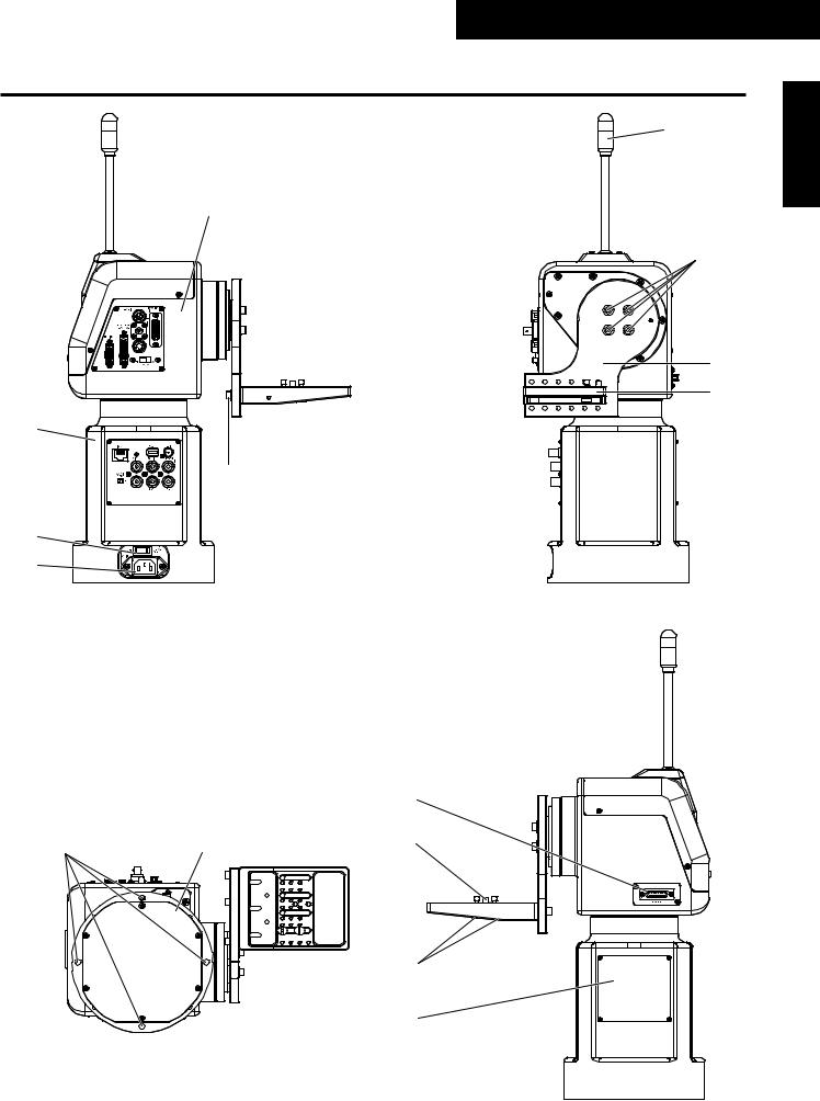
Parts and their function
6
1
7
8
9
2
5
3
4
ENGLISH
|
|
< |
: |
; |
= |
|
>
?
6 (E)
Indoor Pan/Tilt Head AW-PH400
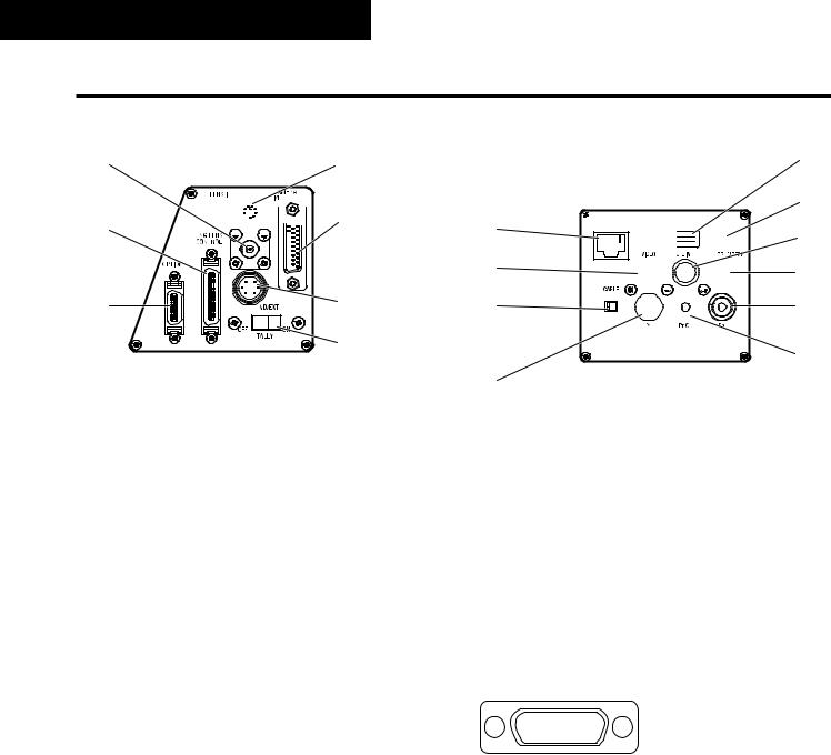
Parts and their function
@ |
C |
A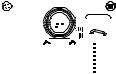 D
D
B |
E |
|
F |
Rotary head connector panel
1Rotary head
This rotates in the horizontal direction.
2Pedestal
3POWER ON/OFF switch
When this is set to ON, the unit’s power is turned on; when it is set to OFF, it is turned off.
4AC 100 inlet [AC IN] (AC 3-point inlet)
Connect the accessory AC power cable to this inlet.
5Camera mounting base mounting screws
M5!20 mm hexagon socket head screws, M5 flat washers (3 of each provided as accessories)
These parts are used to secure the camera mounting base to the rotary arm.
6Tally lamp (accessory)
This is lit up red by the selected signals.
7Rotary arm mounting screws
M5!20 mm hexagon socket head screws, M5 flat washers (4 of each provided as accessories)
These parts are used to secure the rotary arm to the rotary head.
8Rotary arm
This rotates in the vertical direction.
9Camera mounting base
Mount the convertible camera on this base.
K
L G 

 M H
M H 
 N I
N I 


 O
O
P
JPedestal connector panel
:Pan/tilt head mounting holes
These four holes are used when installing the pan/tilt head.
;Bottom panel
<PROMPTER connector
The prompter is connected to this connector.
The maximum current which can be supplied from the DC 12V OUT socket is 2A.
When the prompter is connected, the pan/tilt head’s speed is reduced to about one-third.
87654321
?>=<;:9
Pin layout as seen facing the prompter connector
Pin No. |
Signal Name |
|
1 |
|
– – – |
|
|
|
|
9 |
PROMPTER VIDEO GND |
|
|
|
2 |
|
PROMPTER VIDEO |
|
|
|
|
10 |
– – – |
|
|
|
3 |
|
– – – |
|
|
|
|
11 |
– – – |
4 |
|
DC 12V OUT |
|
12 |
GND |
5 |
|
– – – |
|
|
|
|
13 |
– – – |
|
|
|
6 |
|
– – – |
|
|
|
|
14 |
DETECT |
|
|
|
7 |
|
– – – |
|
|
|
|
15 |
GND |
|
|
|
8 |
|
– – – |
7 (E)

Indoor Pan/Tilt Head AW-PH400
Parts and their function
=Guide pin |
END/EXT connector [ND/EXT] |
Use this to determine the direction in which the camera is |
This is for the control of the ND filter and lens extender of |
to be mounted. |
the motorized lens unit. |
|
Connect this connector when using a motorized lens unit |
>Camera mounting screws (U1/4” 20UNC) |
with ND filter and lens extender functions. |
These are used to secure the camera firmly after it has |
The compatible connector is the R03-P6M or R03-PB6M |
been mounted. |
made by Tajimi Electronics Co., Ltd. |
ENGLISH
?Side blank panel
ND signal |
CVCC (+12V) |
This is used when the mounting direction of the pedestal connector panel is to be changed.
@SDI IN connector [SDI IN]
Use a coaxial cable to connect this to the SDI OUT connector on the AW-PB504 SDI card or other card installed in the convertible camera.
AENG LENS CONTROL connector [ENG LENS CONTROL]
Use this when an ENG lens is to be used. An optional connecting cable is required.
BOPTION connector [OPTION]
The optional AW-RL400 roll unit is connected here using the cable supplied with the AW-RL400.
CLENS I/F connector [LENS I/F]
This is used to control the zooming and focusing of the motorized lens unit. Use the motorized lens unit’s remote (zoom/focus) control cable to make the connection.
DCAMERA I/F connector [CAMERA I/F]
This is used for the control of the convertible camera. Use the camera cable supplied with the AW-PH400 to connect the connector with the REMOTE connector on the camera.
Depending on the functions of the optional card, a special camera cable (sold separately) is required.
A F
ND return |
B |
E |
CGND |
C D
EXT return
EXT signal
(Pin layout as seen from cable end)
FTALLY OFF/ON switch [TALLY]
When this is set to ON, the tally lamp is lit by the selected signals. When it is set to OFF, the (6) tally lamp will not light even if the selected signals are supplied.
GCONTROL IN IP/RP connector [IP/RP]
This is the connector for the control of signals of the camera and pan/tilt head.
It is connected to the CONTROL OUT TO PAN/TILT connector on the AW-RP400 pan/tilt head controller. Use a 10BASE-T (equivalent to UTP category 5) straight cable for the connecting cable.
HVIDEO connector [VIDEO]
This the output connector for the camera’s video signals. It is connected to the Y/VIDEO connector on the AW-RC400 cable compensator or monitor, etc.
Use a BNC coaxial cable for the connecting cable.
ICABLE COMP OFF/ON switch [CABLE COMP]
When this is set to ON, signals which have been cablecompensated for the equivalent of 500 meters are output from the VIDEO connector and the Y, Pr and Pb connectors.
When this switch is used in conjunction with the AW-RC400 cable compensator, the video cable can be extended up to a maximum of 1000 meters.
8 (E)

Indoor Pan/Tilt Head AW-PH400
Parts and their function
JY connector [Y]
This is the output connector for the camera’s video signals.
It is connected to the Y/VIDEO connector on the AW-RC400 cable compensator or monitor, etc. Use a BNC coaxial cable for the connecting cable. The AW-PB302 RGB card must be installed if the AW-E300, AW-E300A, AW-E600, AW-E800 or AW-E800A convertible camera is to be used.
K1394 connector [1394]
This is used for the control of the convertible camera and pan/tilt head equipped with an IEEE1394 card such as the AW-PB310.
Use an IEEE1394 cable for the connecting cable.
LSDI connector [SDI]
This is the output connector for the camera’s video signals.
When the AW-PB504 SDI card or other card is inserted in the convertible camera for use, SDI signals can be output.
Use a BNC coaxial cable for the connecting cable.
MG/L IN connector [G/L IN]
This is the genlock signal input connector.
It is connected to the G/L OUT connector on the AW-RC400 cable compensator or other unit.
Use a BNC coaxial cable for the connecting cable.
NPROMPTER IN connector [PROMPTER IN]
The video signals for the prompter are input to this connector.
Use a BNC coaxial cable for the connecting cable.
OPb connector [Pb]
This is the output connector for the camera’s video signals.
It is connected to the Pb connector on the AW-RC400 cable compensator or monitor, etc.
Use a BNC coaxial cable for the connecting cable.
PPr/C connector [Pr/C]
This is the output connector for the camera’s video signals.
It is connected to the Pr/C connector on the AW-RC400 cable compensator or monitor, etc.
Use a BNC coaxial cable for the connecting cable.
9 (E)
Indoor Pan/Tilt Head AW-PH400
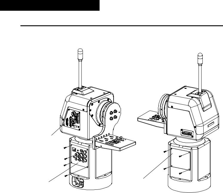
Installation (Be sure to ask your dealer to install the unit.)
$ Assembling the pan/tilt head
1Attaching the camera mounting base
Attach the camera mounting base to the rotary arm using the three screws. The mounting direction differs depending on the installation method used.
For installation on the ceiling
2Attaching the rotary arm
ENGLISH
Attach the rotary arm to the rotary head using the four screws. The mounting direction differs depending on the installation method used.
For a stand-alone installation
Rotary arm
Rotary head
Camera mounting base |
|
Rotary arm |
Camera mounting base |
|
|
|
Rotary head |
|
Tally lamp |
3Mounting the tally lamp
Remove the four screws to remove the top cover. Remove the two screws to remove the blank panel.
Mount the tally lamp, and secure it using the screws used to
attach the blank panel.
Connect the tally lamp’s connector. Blank panel Attach the top cover, and secure it using the four screws.
Top cover
≥Tighten up the screws securely to ensure that they will not come loose during use.
10 (E)

Indoor Pan/Tilt Head AW-PH400
Installation (Be sure to ask your dealer to install the unit.)
$ Setting the mounting direction switch
Set the switch as follows when the unit is to be installed on the ceiling. (This switch was set to the stand-alone installation position at the factory.)
1 Remove the four screws, and gently remove the pedestal connector panel.
2Set switch S1 on the PCB inside the pan/tilt head as follows.
For stand-alone installation:
Set S1 to the rear position (T). (Factory setting)
For installation on the ceiling:
Set S1 to the front position (H).
3Upon completion of the setting, return the pedestal connector panel to its original position, and attach it using the screws. (Take care not to pinch or disconnect the wires.)
Rear position (T) |
|
|
for stand-alone |
|
|
installation |
S1 |
|
S1 |
||
Pedestal connector panel |
Front position (H) for installation on the ceiling
≥ Be absolutely sure to turn off the power before changing the position of this switch.
11 (E)

Indoor Pan/Tilt Head AW-PH400
Installation (Be sure to ask your dealer to install the unit.)
$ Setting the PCB switches
The switches on the CONNECTOR PCB will need to be set in accordance with the signals to be transmitted and the equipment to be connected to the pan/tilt head.
(The switches are set to support analogue/SDI at the factory.)
≥Analogue/SDI support
IP/IEEE switch: IEEE 422/IP switch: 422
≥Web card support
IP/IEEE switch: IP 422/IP switch: IP
≥IEEE1394 card support
IP/IEEE switch: IEEE 422/IP switch: 422
ENGLISH
|
IP/IEEE switch |
|
422/IP switch |
|
|
|
|
|
|
|
|
|||||||||||||||||||||
|
|
|
|
|
|
|
|
|
|
|
|
|
|
|
|
|
|
|
|
|
|
|
|
|
|
|
|
|
|
|
|
|
|
|
|
|
|
|
|
|
|
|
|
|
|
|
|
|
|
|
|
|
|
|
|
|
|
|
|
|
|
|
|
|
|
|
|
|
|
|
|
|
|
|
|
|
|
|
|
|
|
|
|
|
|
|
|
|
|
|
|
|
|
|
|
|
|
|
|
|
|
|
|
|
|
|
|
|
|
|
|
|
|
|
|
|
|
|
|
|
|
|
|
|
|
|
|
|
|
|
|
|
|
|
|
|
|
|
|
|
|
|
|
|
|
|
|
|
|
|
|
|
|
|
|
|
|
|
|
|
|
|
|
|
|
|
|
|
|
|
|
|
|
|
|
|
|
|
|
|
|
|
|
|
|
|
|
|
|
|
|
|
|
|
|
|
|
|
|
|
|
|
|
|
|
|
|
|
|
|
|
|
|
|
|
|
|
|
|
|
|
|
|
|
|
|
|
|
|
|
|
|
|
|
|
|
|
|
|
|
|
|
|
|
|
|
|
|
|
|
|
|
|
|
|
|
|
|
|
|
|
|
|
|
|
|
|
|
|
|
|
|
|
|
|
|
|
|
|
|
|
|
|
|
|
|
|
|
|
|
|
|
|
|
|
|
|
|
|
|
|
|
|
|
|
|
|
|
|
|
|
|
|
|
|
|
|
|
|
|
|
|
|
|
|
|
|
|
|
|
|
|
|
|
|
|
|
|
|
|
|
|
|
|
|
|
|
|
|
|
|
|
|
|
|
|
|
|
|
|
|
|
|
|
|
|
|
|
|
|
|
|
|
|
|
|
|
|
|
|
|
|
|
|
|
|
|
|
|
|
|
|
|
|
|
|
|
|
|
|
|
|
|
|
|
|
|
|
|
|
|
|
|
|
|
|
|
|
|
|
|
|
|
|
|
|
|
|
|
|
|
|
|
|
|
|
|
|
|
|
|
|
|
|
|
|
|
|
|
|
|
|
|
|
|
|
|
|
|
|
|
|
|
|
|
|
|
|
|
|
|
|
|
|
|
|
|
|
|
|
|
|
|
|
|
|
|
|
|
|
|
|
|
|
12 (E)
Indoor Pan/Tilt Head AW-PH400
Installation (Be sure to ask your dealer to install the unit.)
$ Changing the mounting position of the pedestal connector panel
If necessary, the position at which the pedestal connector panel is mounted can be moved to the opposite side of the unit.
Rotary head connector panel
Pedestal connector panel |
Side blank panel |
(opposite side) |
1 Remove the four screws for the pedestal connector panel, and pull out the pedestal connector panel.
2 Disconnect all six connectors of the PCB at the back of the pedestal connector panel.
3 Remove the four screws for the side blank panel, and remove the side blank panel.
4 Move the pedestal connector panel to the opposite side, and re-connect the connectors of the PCB as before.
5 Screw down the pedestal connector panel and side blank panel.
≥ Neither the mounting position nor the mounting direction of the rotary head connector panel can be changed.
13 (E)
Indoor Pan/Tilt Head AW-PH400
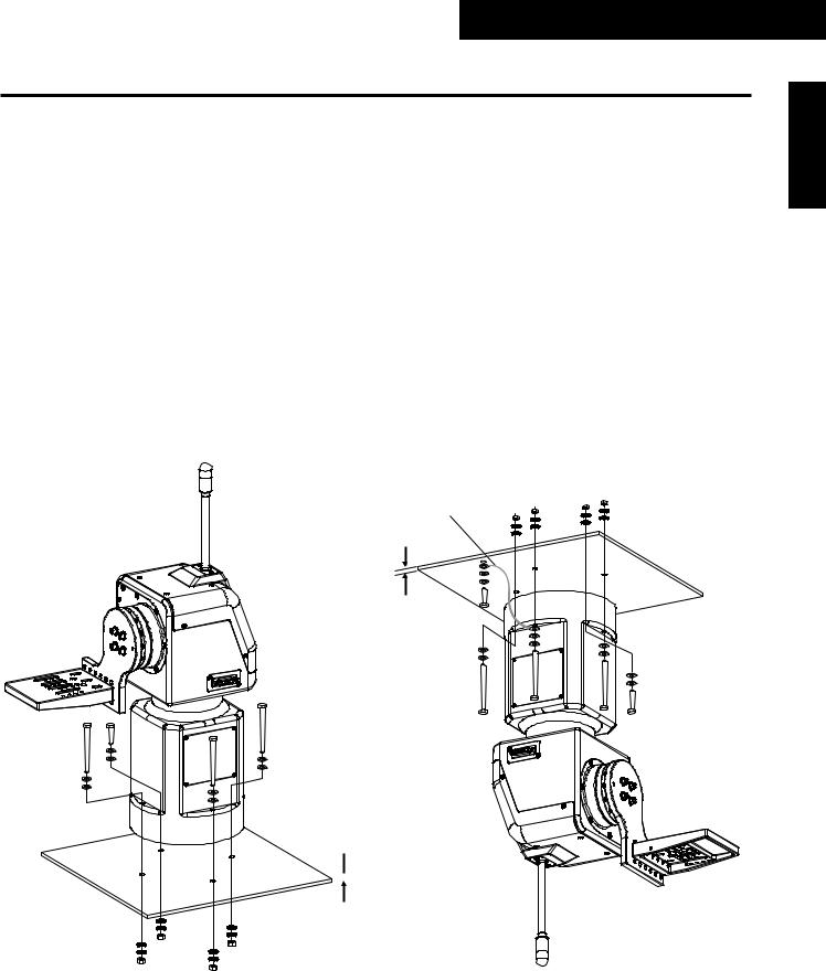
Installation (Be sure to ask your dealer to install the unit.)
$ Installing the pan/tilt head
When installing the pan/tilt head, follow the instructions below carefully.
In order to prevent accidents resulting when the product becomes dislodged or falls down, be absolutely sure to proceed as instructed. Do not install the pan/tilt head on its side since its prescribed operation and performance cannot be ensured.
≥After the pan/tilt head has been installed, mount the camera on it.
≥When installing the pan/tilt head, use the four mounting holes to secure the pan/tilt head firmly.
≥Use the M6 hexagon head bolts (including one short bolt) for installation.
≥Use hexagon head bolts which are longer than the thickness (t) of the mounted member + 25 mm.
≥As shown in the figure, use flat washers, spring washers and hexagon nuts for the hexagon head bolts.
≥Use a wrench of the appropriate size to tighten up the hexagon head bolts.
≥When installing the pan/tilt head on the ceiling, attach the wire together with the bolts, and then anchor them securely to a rigid part of the ceiling.
≥Use a wire which is strong enough to bear the weight of the entire pan/tilt head (pan/tilt head, camera and lens cable).
≥Install the pan/tilt head in such a way that the equipment and cable attached to it will not make contact with any surrounding objects when the head is swiveled.
ENGLISH
For a stand-alone installation |
|
For installation on the ceiling |
|
|
|
Wire
t
 t
t
When installing the pan/tilt head, do not forcibly turn the rotary head or rotary arm manually. Doing so may result in malfunctioning.
14 (E)

Indoor Pan/Tilt Head AW-PH400
Installation (Be sure to ask your dealer to install the unit.)
$ Mounting the camera
1Select the positions of the guide pin and camera mounting screws in accordance with the camera and lens to be used, and mount the camera. When mounting the camera on the pan/tilt head, be very careful to ensure that the camera does not fall off or fall down.
For a stand-alone installation
Guide pin
Flat washers
Camera mounting screws
For installation on the ceiling
Guide pin
Flat washers
Camera mounting screws
15 (E)
Indoor Pan/Tilt Head AW-PH400
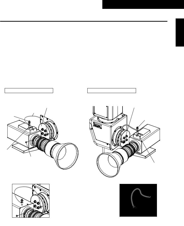
Installation (Be sure to ask your dealer to install the unit.)
$ Attaching the chain
When mounting the AW-E750 camera
1Use the chain mounting screw (M4!8 mm with flat washer and spring washer) to attach one end of the chain to the pan/tilt head’s arm.
2 Mount the mounting spacer on the top panel of the camera.
3Use the chain mounting screw (M4!6 mm with flat washer and spring washer) to attach the other end of the chain to the screw hole of the mounting spacer.
When mounting the AW-E350 or AW-E650 camera
1Use the chain mounting screw (M4!8 mm with flat washer and spring washer) to attach one end of the chain to the pan/tilt head’s arm.
2Use the chain mounting screw (M4!6 mm with flat washer and spring washer) to attach the other end of the chain to the screw hole of the top panel of the camera.
ENGLISH
For a stand-alone installation
≥ Camera: AW-E750
M4!6 mm chain |
Arm |
mounting screw |
Chain |
with flat washer |
|
and spring washer |
|
Mounting |
|
|
spacer |
|
|
(supplied with |
M4!8 mm chain |
|
AW-E750) |
||
mounting screw |
||
|
with flat washer |
|
|
and spring washer |
For installation on the ceiling
≥ Camera: AW-E750
M4!8 mm chain mounting screw with flat washer and spring washer
M4!6 mm chain mounting screw with flat washer and spring washer
Mounting spacer (supplied with AW-E750)
≥ Camera: AW-E650, AW-E350 |
≥ Camera: AW-E650, AW-E350 |
Be absolutely sure to tighten up the mounting spacer and screws securely using a tool such as a screwdriver.
16 (E)
Indoor Pan/Tilt Head AW-PH400
Replacing the consumable parts
$ Replacing the battery
The battery has a service life of approximately 5 years.
The unit stores the preset positions, limiters and other data in its memory. This data is retained even when the power is turned off, but if the internal battery has reached the end of its service life, the data will be lost when the power is turned off.
Replace a battery that has lost its charge with a new one. (Battery used: CR2032 manganese dioxide-lithium battery)
$ How to remove the battery
1Remove the four screws, and remove the pedestal connector panel.
2Push the battery in the direction indicated by the arrow in the figure, and slide it out.
3 With the battery slid out, raise it from underneath the part with the arrow.
4 After disengaging the part with the arrow from the battery holder, pull the battery out toward yourself.
Replace the lithium battery here.
$ How to install the battery |
|
|
1 Make the “+” side of the new battery to the front side, and insert |
|
|
its end into the battery holder from the direction of the arrow. |
|
|
2 Push the battery into the holder while pushing the battery in the |
Pedestal connector panel |
|
direction of the arrow. |
||
|
||
3 Attach the pedestal connector panel using the four screws. |
|
$ Replacing the motor
Replace the motor when it ceases to operate properly.
For details on the motor replacement, consult your dealer.
$ Replacing the belt
Replace the belt when the preset stop accuracy has deteriorated.
For details on the belt replacement, consult your dealer.
$ Replacing the gear
Replace the gear when the preset stop accuracy has deteriorated.
For details on the gear replacement, consult your dealer.
The motor, gear and belt are consumables.
They need to be replaced at periodic intervals.
17 (E)

Specifications
Supply voltage: |
AC 240V, 50/60 Hz |
Power consumption: 145W
1 indicates safety information.
Genlock input: |
BNC |
|
Black burst or composite video signal |
Prompter input |
|
(PROMPTER IN): |
BNC |
|
Through output to PROMPTER connector |
Prompter output |
|
(PROMPTER OUT): |
D-SUB 15-pin |
Camera video output |
|
Indoor Pan/Tilt Head AW-PH400
ENGLISH
VIDEO: |
BNC, 75-ohm output, 1 Vp-p |
|
Connecting cable: 5C-2V, max. 1000 meters |
Y, Pr/C, Pb: |
Y/C |
|
Y: 1 Vp-p/75 ohms |
|
C: 0.285Vp-p/75 ohms (burst) |
|
Component video: |
|
Y: 1 Vp-p/75 ohms |
|
Pr: 0.7Vp-p/75 ohms |
|
Pb: 0.7Vp-p/75 ohms |
|
Connecting cable: 5C-2V, max. 1000 meters |
SDI: |
BNC |
Camera, pan/tilt head control: |
RJ45, RS-485, pan/tilt head control signal output |
RP/IP |
Connecting cable: 10BASE-T straight cable (equivalent to UTP category 5), |
|
max. 500 meters |
Functions/performance: |
Maximum load-bearing capacity: 8 kg |
|
Tilt range: 190 degrees (approx. ±95 degrees) |
|
The tilt range is subject to restrictions depending on the cable and lens of camera to be |
|
mounted on pan/tilt head. |
|
Pan range: 400 degrees (approx. ±200 degrees) |
|
Maximum operating speed: 90 degrees/sec. |
|
(Maximum operating speed with prompter mounted: 30 degrees/sec.) |
|
Repeatability: ±30” |
|
Noise level: Less than NC30 (at less than 30 degrees/sec.) |
Ambient operating temperature: 0°C to +45°C |
|
Storage temperature: |
–20°C to +60°C |
Ambient operating humidity: |
30% to 90% (no condensation) |
Dimensions (W!H!D): |
???!???!??? mm |
Weight: |
Approx. ?? kg |
Finish: |
AV ivory paint (colour resembling Munsell 7.9Y6.8/0.8) |
18 (E)

Pan/Tilt Head Controller AW-RP400
Introduction
≥This pan/tilt head controller enables up to five AW-PH400 indoor pan/tilt heads to be controlled.
≥By connecting the AW-CB400 remote operation panel or WV-CB700A remote control box to the controller, the convertible cameras mounted on the pan/tilt heads can be controlled at the same time.
≥By installing an additional controller, two of the five units in the pan/tilt head system can be controlled at the same time.
≥Up to ten tracing memories can be accommodated.
≥Up to 50 preset memories can be set.
≥The connection distance between the controller and pan/tilt head system can be extended up to a maximum of 500 meters.
NOTE
≥The AW-RP400 cannot be used to control the model AW-PH300, AW-PH300A, AW-PH350, AW-PH500 or AW-PH600 pan/tilt heads.
≥Before using the controller, the movement range (limiters) of the pan/tilt head system must be set without fail.
≥When the AW-PH400 controller is to be discarded at the end of its service life, ask a specialized contractor to dispose of it properly in order to protect the environment.
Accessories |
|
Zoom switch ................................................................................. |
1 |
Plug (D-SUB 15-pin) for tally/INCOM system ...................... |
1 set |
Rack-mounting adaptors ............................................................. |
2 |
Mounting screws (M4!8 mm) .................................................... |
4 |
19 (E)
Pan/Tilt Head Controller AW-RP400
Parts and their function
$ Front panel |
; < = > ? @ A B C D |
E F G H I |
1 |
ENGLISH |
|
||||
2 |
|
|
|
|
3 |
|
|
|
|
4 |
|
|
|
J |
|
|
|
|
|
5 |
|
|
|
|
6 |
|
|
|
K |
7 |
|
|
|
|
8 |
|
|
|
|
9 |
|
|
|
|
: |
|
|
|
L |
|
|
|
|
1EXT CONT [M/S] switch |
NOTE |
This switch is normally kept at the [M] (master) position. When an additional AW-RP400 controller has been installed, set the EXT CONT switch on the additional unit to [S] (slave).
If no additional AW-RP400 controller is going to be installed, the EXT CONT switch on this controller must be kept at the [M] (master) position without fail.
2OPERATE lamp
This lights up green when the (3) OPERATE switch is at ON. It goes off when the switch is set to OFF.
3OPERATE [OFF/ON] switch
When this switch is set to [ON], the power supply from the connected pan/tilt heads to the cameras is turned on, and system control is enabled.
When it is set to [OFF], the power supply from the connected pan/tilt heads to the cameras is turned off.
When an additional AW-RP400 controller is installed and used, it will not be possible to exercise control from the slave controller unless the OPERATE switches not only on the slave controller but on the master controller as well are set to [ON]. Remember to set the OPERATE switch on the slave controller to [ON] first before setting the OPERATE switch on the master controller to [ON].
4INCOM jack
The INCOM (inter-communication) headset is connected here.
5LEVEL control
Use this to adjust the volume of the headset’s receiver.
6CALL button
When this button is pressed, the buzzer of the connected controller sounds, and the CALL button lamp lights.
20 (E)

Pan/Tilt Head Controller AW-RP400
Parts and their function
7IRIS [AUTO/MANU/LOCK] button
Use this to select the method for adjusting the lens iris of the cameras in the currently selected pan/tilt head system.
Each time it is pressed, the setting is switched in the sequence of AUTO, MANU and LOCK.
AUTO: The cameras automatically adjust the lens iris in accordance with the light quantity, and the IRIS button lamp lights.
MANU: The lens iris is adjusted manually using the IRIS dial. At this setting, the IRIS button lamp is off.
LOCK: The lens iris is locked at the manually adjusted setting. It does not move even when the (9) IRIS dial is turned. In this status, the IRIS button lamp flashes slowly.
While MANU or LOCK is selected, the IRIS button lamp starts flashing quickly when the IRIS dial is turned: this indicates that the lens iris cannot be controlled even when the (9) IRIS dial is turned.
≥The IRIS button on the controller does not work when the WV-CB700A remote control box is connected to the controller. Select AUTO or MANU using the IRIS [AUTO/MAN] button on the WV-CB700A.
8SD CARD slot
This slot is where the SD memory cards are inserted. The pan/tilt head and camera setting can be stored on these cards.
9IRIS dial
The lens iris can be adjusted by turning this dial while the (7) IRIS [AUTO/MANU/LOCK] button is set to MANU. The iris is opened by turning the dial clockwise and stopped down by turning it counterclockwise.
≥The IRIS dial on the controller does not work when the WV-CB700A remote control box is connected to the controller. Adjust the iris using the IRIS control on the WV-CB700A.
:ZOOM lever/FOCUS dial
Use the ZOOM lever to adjust the lens zoom. The TELE (telephoto) and WIDE (wide angle) settings are established by the direction in which the lever is tilted; the zooming speed is adjusted by the angle to which the lever is tilted.
The lens is focused using the FOCUS dial on the top of the lever.
;PAN indicator
Sixteen LEDs are used to display the position of the pan/tilt head in the horizontal rotational direction for 200 degrees to the left or right.
When the pan/tilt head is rotated to the right by more than 180 degrees up to 200 degrees, the 180-degree LED flashes, and LEDs on its left light.
Conversely, when the pan/tilt head is rotated to the left by more than 180 degrees up to 200 degrees, the 180degree LED flashes, and LEDs on its right light.
0o
90° to the left |
90° to the right |
180° to the left or right
<IRIS indicator
The position of the lens iris in the currently selected
pan/tilt head system is indicated by a 6-step display (CLOSE > OPEN).
=ZOOM indicator
The position of the lens zoom in the currently selected
pan/tilt head system is indicated by a 6-step display (WIDE > TELE).
>FOCUS indicator
The position of the lens focus in the currently selected
pan/tilt head system is indicated by a 6-step display (NEAR > FAR).
?OPTION switches [A to H]
The “NOT USE”, “LAMP”, “DEFROSTER”, “WIPER”, “HEATER/FAN”, “AF”, “ND”, “OPTION” and “EXTENDER” functions can be allocated to OPTION switches A to H by menu settings.
@HOME button
Press this to move the pan/tilt head and roll unit to the home position.
ALCD CONTRAST control
Use this to adjust the contrast of the LCD panel.
21 (E)

Pan/Tilt Head Controller AW-RP400
Parts and their function
BMEMORY button
When one of the (C) PRESET MEMORY selection buttons [1] to [50] is pressed while holding down the MEMORY button, the settings of the pan/tilt head system can be registered in that PRESET MEMORY selection button.
The MEMORY button flashes if the pan/tilt head selected by the (H) CONTROL SELECT button is not connected or its power has not been turned on.
CPRESET MEMORY selection buttons [1] to [50]
Use these buttons to call the settings registered in them. When data has been registered in the tracing memories, the recording/play time displays appear.
DLCD panel
The current setting statuses are displayed on this panel.
EMENU/LIMIT button
Hold down this button for two or more seconds to turn the setting menu ON or OFF.
When (C) PRESET MEMORY selection button [5], [10], [15], [20], [25] or [30] is pressed while holding down the MENU/LIMIT button, ON/OFF control over the limiters can be exercised.
FCONT dial
This is used for the setting menu operations.
GTALLY lamps [1] to [5]
When tally signals are supplied to the (O) TALLY/INCOM connectors [1] to [5] on the rear panel, the lamps with the numbers corresponding to those connectors light up.
When tally signals are supplied to the tally connectors [1] to [5] of the AW-CB400 remote operation panel, if this panel is connected to the pan/tilt head controller, the lamps with the numbers corresponding to those connectors also light up.
HCONTROL SELECT buttons [1] to [5]
The (R) CONTROL OUT TO PAN/TILT HEAD [P1] to [P5] connectors on the rear panel can be selected by pressing buttons [1] to [5]. The button lamps corresponding to the numbers of the buttons selected light, and the selected pan/tilt head systems can be controlled.
When the (S) MONI SEL OUT connector on this controller is connected to the MONI SEL IN connector on the AW-RC400 cable compensator, the images of the camera connected to the MONI1 or MONI2 connector on the AW-RC400 can be output.
≥When two AW-RP400 controllers are connected, the combination of the controllers which select the monitor output can be set on the menu.
IANOTHER CONTROL lamps [1] to [5]
When another AW-RP400 controller is connected, these lamps indicate the numbers of the pan/tilt head systems selected by the additional AW-RP400 controller.
JTRACING MEMORY [START POINT, STOP, RESTORE, RESET, 1 to 10] buttons
Use these for the tracing memory operations. For details on operation, refer to the tracing memory section.
KSPEED controls [ZOOM/FOCUS/PAN/TILT/ROTATION]
These enable the pan/tilt head, lens and roll unit control speeds to be adjusted.
By turning these controls as far as they will go in the counterclockwise direction, operation of the pan/tilt heads and lenses can be prevented even when control is exercised using the joystick, etc.
LPAN/TILT lever/ROTATION control switch
Use these to adjust the direction of the pan/tilt heads. When the lever is tilted to the left or right, the pan/tilt heads move toward the left or right; when it is tilted up or down, they move upward or downward. The movement speed can be adjusted by the angle to which the lever is tilted.
Further, the angle of the AW-RL400 roll unit can be adjusted using the ROTATION control switch on the front of the lever. By pressing the top part of the ROTATION control switch, the roll unit rotates clockwise; by pressing the bottom part, it rotates counterclockwise. The speed of the rotation changes in accordance with the amount of pressure applied.
ENGLISH
22 (E)
Pan/Tilt Head Controller AW-RP400
Parts and their function
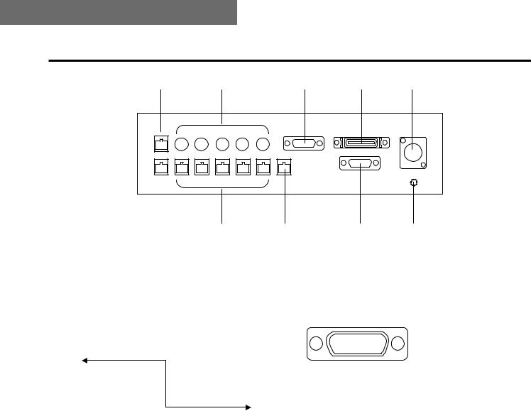
$ Rear panel |
M |
N |
O |
P |
Q |
R |
S |
T |
U |
MEXT CONT IN/OUT connectors |
|
OTALLY/INCOM connector |
|
When an additional AW-RP400 controller is to be provided, connect these connectors on the two AW-RP400 controllers using a 10BASE-T (equivalent to UTP category 5) straight cable.
Master |
|
|
Slave |
||||||||||||||
controller |
|
controller |
|||||||||||||||
AW-RP400 |
|
AW-RP400 |
|||||||||||||||
|
|
|
|
|
|
|
|
|
|
|
|
|
|
|
|
||
|
|
|
|
|
|
|
|
|
|
|
|
|
|
|
|
|
|
|
|
|
|
|
|
|
|
|
|
|
|
|
|
|
|
|
|
|
|
|
|
|
|
|
|
|
|
|
|
|
|
|
|
|
|
EXT CONT |
|
EXT CONT |
|||||||||||||||
|
|
IN |
|
|
|
IN |
|||||||||||
|
|
|
|
|
|
|
|
10BASE-T |
|
|
|
|
|
|
|
|
|
|
|
|
|
|
|
|
|
|
|
|
|
|
|
|
|
||
|
|
|
|
|
|
|
|
|
|
|
|
|
|
|
|
||
|
|
|
|
|
|
|
|
|
|
|
|
|
|
|
|
||
EXT CONT |
EXT CONT |
||||||||||||||||
10BASE-T straight cable |
|||||||||||||||||
|
|
OUT |
|
|
|
OUT |
|||||||||||
NCAMERA CONTROL IN FROM RCB [P1] to [P5] connectors
Connect the WV-CB700A remote control boxes to these connectors.
The cameras installed on the pan/tilt heads corresponding to the ports where the WV-CB700A boxes have been connected can then be controlled.
When even one WV-CB700A box is connected, the cameras cannot be controlled from the AW-CB400 remote operation panel even if the AW-CB400 is connected.
Connect this to the TALLY/INCOM connector on the video switcher or other unit.
When the TALLY input connector is set to the GND level, the TALLY lamp on the controller or pan/tilt head lights. Do not apply a voltage in excess of 5V to this connector.
87654321
?>=<;:9
Pin layout as seen from the back panel of AW-RP400
Pin No. |
Signal name |
|
1 |
|
TALLY1 |
|
|
|
|
9 |
TALLY2 |
|
|
|
2 |
|
TALLY3 |
|
|
|
|
10 |
TALLY4 |
|
|
|
3 |
|
TALLY5 |
|
|
|
|
11 |
TALLY GND |
|
|
|
4 |
|
– – – |
|
12 |
– – – |
5 |
|
– – – |
|
13 |
– – – |
|
|
|
6 |
|
MIC+ |
|
|
|
|
14 |
MIC– |
|
|
|
7 |
|
INCOM GND |
|
|
|
|
15 |
SP– |
|
|
|
8 |
|
SP+ |
Use the accessory plug (D-SUB 15-pin) to connect the tally/INCOM signals to the system.
Connect a 4-wire INCOM system to the INCOM connector.
When an additional controller has been provided or when the AW-CB400 remote operation panel has been connected, the tally or INCOM function of all the units will take effect if tally or INCOM signals are connected to one of the units.
23 (E)

Parts and their function
PREMOTE connector
Connect an external unit to this connector to control the pan/tilt head systems from a PC or other external unit. Connect the connector to the PC using the AW-CA50T9 RS-232C cable.
QDC 12V IN socket
Connect the AW-PS505 AC adaptor (sold separately) to this socket.
RCONTROL OUT TO PAN/TILT HEAD [P1] to [P5] connectors
Connect these connectors to the IP/RP connectors on the AW-PH400 indoor pan/tilt heads using 10BASE-T (equivalent to UTP category 5) straight cables. The cables can be extended up to a maximum of 500 meters.
SMONI SEL OUT connector
Connect this connector to the MONI SEL OUT connector on the AW-RC400 cable compensator using a 10BASE-T (equivalent to UTP category 5) straight cable.
The images of the camera selected by the controller can now be output from the MONITOR1 or MONITOR2 connector on the AW-RC400.
TCAMERA CONTROL IN FROM RCP connector
Connect the AW-CB400 remote operation panel to this connector using the connecting cable packed with the AW-CB400.
The cameras installed on the pan/tilt heads can now be controlled from the AW-CB400.
UGround terminal
Connect this terminal to ground.
Pan/Tilt Head Controller AW-RP400
ENGLISH
24 (E)

Pan/Tilt Head Controller AW-RP400
Menu settings
$ Operation method
1The menu setting items are displayed when the MENU/LIMIT switch is held down for two or more seconds.
2If nothing appears on the bottom line of the LCD display, turn the CONT dial to select a menu item.
3When the CONT dial is pressed, what has been set appears on the bottom line. If more than one setting is involved in the menu item, the settings on the bottom line are switched each time the dial is pressed.
4When a setting is displayed, the setting can be changed by turning the CONT dial.
5Press the CONT dial successively: all the detailed settings come to an end, and the display on the bottom line is cleared, enabling another menu item to be selected.
6To exit the setting menu, hold down the MENU/LIMIT switch for two or more seconds.
Even when a setting is displayed on the bottom line of the LCD display, the menu is exited when the MENU/LIMIT switch is held down for two or more seconds.
AW-RP400
PAN/TILT CONTROLLER
;
PRIORITY
;
DIRECTION SET
;
DIRECTION
PAN NORMAL
;
DIRECTION
TILT NORMAL
;
DIRECTION
TILT REVERSE
;
DIRECTION
;
AW-RP400
PAN/TILT CONTROLLER
25 (E)

Pan/Tilt Head Controller AW-RP400
Menu settings
$ List of menu items and settings
Menu item |
Setting |
Description |
Initial value |
|
|
|
|
PRIORITY |
|
MASTER, SLAVE |
MASTER |
|
|
|
|
DIRECTION |
PAN |
|
|
|
|
|
|
|
TILT |
|
|
|
|
|
|
|
ZOOM |
NORMAL, REVERSE |
NORMAL |
|
|
||
|
FOCUS |
||
|
|
|
|
|
|
|
|
|
IRIS |
|
|
|
|
|
|
|
ROTATION |
|
|
|
|
|
|
SPEED WITH ZOOM POS. |
|
OFF, 1, 2, 3 |
OFF |
|
|
|
|
MEMORY LENGTH |
|
60s, 120s, 300s, 600s |
60s |
|
|
|
|
PRESET SPEED |
|
1 to 25 |
25 |
|
|
|
|
IRIS CONTROL |
|
BOTH, RP400, CB400 |
BOTH |
|
|
|
|
ROTATION SWITCH |
|
ROTATION, FOCUS, ZOOM, IRIS |
ROTATION |
|
|
|
|
OPTION SWITCH |
A |
|
|
|
|
|
|
|
B |
|
|
|
|
|
|
|
C |
NOT USE, LAMP, EFROSTER, WIPER, |
|
|
|
|
|
|
D |
|
|
|
HEATER/FAN, AF, ND, OPTION, |
NOT USE |
|
|
|
||
|
E |
||
|
EXTENDER |
|
|
|
|
|
|
|
F |
|
|
|
|
|
|
|
|
|
|
|
G |
|
|
|
|
|
|
|
H |
|
|
|
|
|
|
CONTROL SELECT MODE |
|
INTERLOCK, UN-INTERLOCK |
INTERLOCK |
|
|
|
|
MONITOR2 SELECT |
(When the controller |
CB400, SLAVE |
CB400 |
|
is the master) |
|
|
|
|
|
|
|
(When the controller |
RP400, CB400 |
RP400 |
|
is the slave) |
|
|
|
|
|
|
BUZZER |
|
OFF, ON |
ON |
|
|
|
|
AUTO RUN |
START No. |
1 to 50 |
1 |
|
|
|
|
|
END No. |
1 to 50 |
50 |
|
|
|
|
|
INTERVAL |
1s to 30s |
1s |
|
|
|
|
|
OPERATE |
STOP, RUN |
STOP |
|
|
|
|
SD CARD |
|
STORE, LOAD |
– – – |
|
|
|
|
ENGLISH
PRIORITY (MASTER/SLAVE)
When two AW-RP400 pan/tilt head controllers have been connected, the priority of the CONTROL SELECT buttons is to be set.
When MASTER is selected as the setting, the master AW-RP400 has priority; when SLAVE is selected, the slave AW-RP400 has priority.
If the AW-RP400 controller with a high priority has selected the pan/tilt heads, which were selected by the AW-RP400 controller with a low priority, the CONTROL SELECT button lamps on the AW-RP400 controller with the low priority start flashing to indicate that the control rights have been ceded to the other controller. This setting is performed using the master AW-RP400 controller.
26 (E)

Pan/Tilt Head Controller AW-RP400
Menu settings
DIRECTION settings (PAN, TILT, ZOOM, FOCUS, IRIS, ROTATION NORMAL/REVERSE)
When the lever or dial is operated, the DIRECTION menu item enables the operational direction of PAN, TILT, ZOOM, FOCUS, IRIS or ROTATION to be set as the user desires.
PAN: When NORMAL is selected, the pan/tilt head moves toward the left when the PAN/TILT lever is tilted to the LEFT and toward the right when it is tilted to the RIGHT. When REVERSE is selected, the head moves in the opposite direction.
TILT: When NORMAL is selected, the pan/tilt head moves upward when the PAN/TILT lever is tilted toward UP and down when it is tilted toward DOWN. When REVERSE is selected, the head moves in the opposite direction.
ZOOM: When NORMAL is selected, the lens zoom moves toward the telephoto end when the ZOOM lever is tilted toward TELE and toward the wide-angle end when it is tilted toward WIDE. When REVERSE is selected, the zoom moves in the opposite direction.
FOCUS: When NORMAL is selected, the lens focus moves toward FAR when the FOCUS dial is turned clockwise and toward NEAR when it is turned counterclockwise. When REVERSE is selected, the lens focus moves in the opposite direction.
IRIS: When NORMAL is selected, the lens iris moves toward open when the IRIS dial is turned clockwise and toward closed when it is turned counterclockwise. When REVERSE is selected, the lens iris moves in the opposite direction.
ROTATION: When NORMAL is selected, the pan/tilt head moves clockwise when the top of the ROTATION control switch is pressed and counterclockwise when the bottom is pressed. When REVERSE is selected, the head moves in the opposite direction.
SPEED WITH ZOOM POS. setting (OFF/1/2/3)
At the OFF setting, the pan and tilt speed does not change in accordance with the zoom position.
At the 1, 2 or 3 setting, the panning and tilting of the pan/tilt head slows down as the zoom approaches the telephoto end, making it easier to adjust the pan or tilt position even at the telephoto end.
The higher the number selected for the setting, the slower the pan and tilt speed at the telephoto end, and the easier it is to adjust the position using a zoom lens with a high magnification rate.
PRESET SPEED setting (1 to 25)
During preset memory data play, this menu item enables the movement speed to the preset positions to be set to one of 25 steps. The higher the setting, the faster the movement speed to the preset positions; conversely, the lower the setting, the slower the movement speed.
IRIS CONTROL setting (BOTH/RP400/CB400)
When the AW-CB400 remote operation panel has been connected to the AW-RP400 controller, this menu item is used to set which controller is to be used to adjust the lens iris.
At the BOTH setting, the lens iris can be controlled from both the AW-RP400 and AW-CB400. At the RP400 setting, it can be controlled only from the AW-RP400; similarly, at the CB400 setting, it can be controlled only from the AW-CB400.
ROTATION SWITCH setting (ROTATION/FOCUS/ZOOM/IRIS)
This menu item enables ROTATION, FOCUS, ZOOM or IRIS to be selected as the function to be controlled by the ROTATION switch.
27 (E)

Pan/Tilt Head Controller AW-RP400
Menu settings
OPTION SWITCH A to H settings
(NOT USE / DEFROSTER / WIPER / HEATER/FAN / AUTO FOCUS / ND / OPTION / EXTENDER)
The following functions can be allocated to OPTION buttons A to H. Different functions can be allocated for different pan/tilt heads.
NOT USE: The button is disabled.
DEFROSTER: This controls the ON and OFF states of the defroster function when using a pan/tilt head system equipped with this function.
Each time the button is pressed, ON is switched to OFF or vice versa.
When the defroster function is ON, the lamp of the button to which this function has been allocated is lit; when it is OFF, the lamp is off.
WIPER: This controls the ON and OFF states of the wiper function when using a pan/tilt head system equipped with this function.
Each time the button is pressed, ON is switched to OFF or vice versa.
When the wiper function is ON, the lamp of the button to which this function has been allocated is lit; when it is OFF, the lamp is off.
HEATER/FAN: This controls the ON and OFF states of the heater/fan function when using a pan/tilt head system equipped with this function.
Each time the button is pressed, ON is switched to OFF or vice versa.
When the heater/fan function is ON, the lamp of the button to which this function has been allocated is lit; when it is OFF, the lamp is off.
OPTION: This controls the short-circuit and open-circuit states of the AC adaptor’s OPTION CONTROL OUT connector when using an AC adaptor for a pan/tilt head system equipped with the OPTION switch control function.
Each time the button is pressed, short circuit is switched to open circuit or vice versa.
When short-circuited, the lamp of the button to which this function has been allocated is lit; when opencircuited, the lamp is off.
ND: This controls the ON and OFF states of the ND filter when using a lens equipped with an ND filter. Each time the button is pressed, ON is switched to OFF or vice versa.
When the ND filter is ON, the lamp of the button to which this function has been allocated is lit; when it is OFF, the lamp is off.
EXTENDER: This controls the ON and OFF states of the extender when using a lens equipped with an extender. Each time the button is pressed, ON is switched to OFF or vice versa.
When the extender is ON, the lamp of the button to which this function has been allocated is lit; when it is OFF, the lamp is off.
AF: This controls the ON and OFF states of the auto focus function when using a lens equipped with this function.
Each time the button is pressed, ON is switched to OFF or vice versa.
When the auto focus function is ON, the lamp of the button to which this function has been allocated is lit; when it is OFF, the lamp is off.
ENGLISH
MEMORY LENGTH setting (60s/120s/300s/600s)
This menu item is used to set the tracing memory data recording time and the number of memories. 60s : 60 sec. ! 10 memories
120s : 120 sec. ! 5 memories
300s : 300 sec. ! 2 memories
600s : 600 sec. ! 1 memory
≥When data has already been registered in a tracing memory, the setting for the recording time and number of memories cannot be changed. To reset a setting, delete the registered data in the tracing memory first.
CONTROL SELECT MODE setting (INTERLOCK/UN-INTERLOCK)
This menu item is for selecting the method used to select the pan/tilt head and camera when the AW-CB400 remote operation panel has been connected to the AW-RP400 controller.
INTERLOCK: When the pan/tilt head and camera system are selected by the AW-RP400 or AW-CB400, the same system is selected by the other unit as well.
UN-INTERLOCK: A different pan/tilt head and camera system can be selected by the AW-RP400 and AW-CB400.
28 (E)

Pan/Tilt Head Controller AW-RP400
Menu settings
MONITOR SELECT setting
This menu item is used to select the controller used to switch the images of the AW-RC400’s MONITOR2 output when the AW-CB400 remote operation panel and a second AW-RP400 have been connected to this AW-RP400 controller and the AW-RC400 cable compensator is used.
By setting the master AW-RP400 and slave AW-RP400, the camera images which have been selected by the controller given in the table below are output as the AW-RC400’s monitor output.
AW-RP400 menu setting |
|
AW-RC400 |
||
|
|
|
|
|
Master unit |
Slave unit |
MONITOR1 |
|
MONITOR2 |
|
|
|
|
|
MON2 = CB400 |
MONITOR2 = setting disabled |
Master RP400 |
|
Master CB400 |
|
|
|
|
|
MON2 = SLAVE |
MONITOR2 = RP400 |
Master RP400 |
|
Slave RP400 |
|
|
|
|
|
MONITOR2 = CB400 |
Master RP400 |
|
Slave CB400 |
|
|
|
|||
|
|
|
|
|
When the cable compensator has been connected to the slave AW-RP400, the images selected by the slave AW-RP400 are output to MONITOR1 on the AW-RP400 and the images selected by the slave AW-CB400 are output to MONITOR2 regardless of this setting.
BUZZER setting (OFF/ON)
This menu item is used to select ON or OFF for the buzzer inside the controller. The buzzer does not sound at the OFF setting.
The buzzer sounds when the CALL button has been pressed or when a tracing memory operation (record, play or change) is started, suspended or ended.
AUTO RUN setting (START No., END No., INTERVAL)
This menu item enables the presets of the pan/tilt head to be repeated automatically.
START No. (1 to 50): END No. (1 to 50): INTERVAL (1s to 30s):
This sets the first number of the preset to be repeated.
This sets the last number of the preset to be repeated.
This sets the stop time at the preset position.
Up to 30 seconds can be set in 1-second increments for the stop time.
OPERATE (STOP/RUN): When RUN is selected, the presets from the START No. to STOP No. are played repeatedly; when STOP is selected, operation stops.
When the PAN/TILT lever is operated, STOP is selected automatically, and operation stops.
SD CARD setting
The menu setting data of this controller, the preset memory data of the pan/tilt heads and the setting data of the cameras can be stored on SD memory cards.
If the MENU button is pressed while STORE is displayed, the setting data is stored on the SD memory card.
If the MENU button is pressed while LOAD is displayed, the data stored on the SD memory card is called, and the settings are loaded into the controller, pan/tilt heads and cameras.
≥ The tracing memory data is not stored.
29 (E)
 Loading...