


Operating Instructions
Memory Card Camera-Recorder
Model No. AG- |
P |
Before operating this product, please read the instructions carefully and save this manual for future use.
F1205S1125-H D |
ENGLISH |
Printed in Japan |
VQT0S52-1 |
|
Before use |
|
|
|
|
|
Description |
of parts |
|
|
|
|
Preparation |
|
|
|
|
|
Shooting |
|
|
|
|
|
Playback |
|
|
|
|
|
Editing |
|
|
|
|
|
Displays |
|
|
|
|
|
Menu |
|
|
|
|
|
Reference |
|
|
|
|
|
CAUTION
RISK OF ELECTRIC SHOCK
DO NOT OPEN
CAUTION: TO REDUCE THE RISK OF ELECTRIC SHOCK, DO NOT REMOVE COVER (OR BACK).
NO USER-SERVICEABLE PARTS INSIDE. REFER TO SERVICING TO QUALIFIED SERVICE PERSONNEL.
The lightning flash with arrowhead symbol, within an equilateral triangle, is intended to alert the user to the presence of uninsulated “dangerous voltage” within the product’s enclosure that may be of sufficient magnitude to constitute a risk of electric shock to persons.
The exclamation point within an equilateral triangle is intended to alert the user to the presence of important operating and maintenance (servicing) instructions in the literature accompanying the appliance.
WARNING:
•TO REDUCE THE RISK OF FIRE OR SHOCK HAZARD, DO NOT EXPOSE THIS EQUIPMENT TO RAIN OR MOISTURE.
•TO REDUCE THE RISK OF FIRE OR SHOCK HAZARD, KEEP THIS EQUIPMENT AWAY FROM ALL LIQUIDS. USE AND STORE ONLY IN LOCATIONS WHICH ARE NOT EXPOSED TO THE RISK OF DRIPPING OR SPLASHING LIQUIDS, AND DO NOT PLACE ANY LIQUID CONTAINERS ON TOP OF THE EQUIPMENT.
CAUTION:
TO REDUCE THE RISK OF FIRE OR SHOCK HAZARD AND ANNOYING INTERFERENCE, USE THE RECOMMENDED ACCESSORIES ONLY.
CAUTION:
THE AC RECEPTACLE (MAINS SOCKET OUTLET) SHALL BE INSTALLED NEAR THE EQUIPMENT AND SHALL BE EASILY ACCESSIBLE.
TO COMPLETELY DISCONNECT THIS EQUIPMENT FROM THE AC MAINS, DISCONNECT THE POWER CORD PLUG FROM THE AC RECEPTACLE.
CAUTION:
Danger of explosion or fire if battery is mistreated.
•Replace only with same or specified type.
•Do not disassemble or dispose of in fire.
•Do not store in temperatures over 140°F (60°C).
•Use specified charger for rechargeable batteries.
•Do not recharge the battery if it is not a rechargeable type.
For Remote Controller
•Replace battery with part No. CR2025 only.
•Do not recharge the battery.
Camera-Recorder
The rating plate is on the underside of the Camera-Recorder
AC Adapter
The rating plate is on the underside of the AC Adapter.
Disconnect the AC mains plug from the AC mains socket when not in use.
CAUTION:
In order to maintain adequate ventilation, do not install or place this unit in a bookcase, built-in cabinet or any other confined space. To prevent risk of electric shock or fire hazard due to overheating, ensure that curtains and any other materials do not obstruct the ventilation.
 indicates safety information.
IMPORTANT
“Unauthorized recording of copyrighted television programs, video tapes and other materials may infringe the right of copyright owners and be contrary to copyright laws.”
2

FCC NOTICE (USA)
Declaration of Conformity
Model Number: |
AG-HVX200P |
Trade Name: |
PANASONIC |
Responsible Party: |
Panasonic Corporation of North America One Panasonic Way, Secaucus, NJ |
|
07094 |
Support contact: |
Panasonic Broadcast & Television Systems Company 1-800-524-1448 |
This device complies with Part 15 of FCC Rules. Operation is subject to the following two conditions:
(1) This device may not cause harmful interference, and (2) this device must accept any interference received, including interference that may cause undesired operation.
To assure continued compliance, follow the attached installation instructions and do not make any unauthorized modifications.
CAUTION:
This equipment has been tested and found to comply with the limits for a Class B digital device, pursuant to Part 15 of the FCC Rules. These limits are designed to provide reasonable protection against harmful interference in a residential installation. This equipment generates, uses and can radiate radio frequency energy and, if not installed and used in accordance with the instructions, may cause harmful interference to radio communications. However, there is no guarantee that interference will not occur in a particular installation. If this equipment does cause harmful interference to radio or television reception, which can be determined by turning the equipment off and on, the user is encouraged to try to correct the interference by one of the following measures:
•Reorient or relocate the receiving antenna.
•Increase the separation between the equipment and receiver.
•Connect the equipment into an outlet on a circuit different from that to which the receiver is connected.
•Consult the dealer or an experienced radio/TV technician for help.
The user may find the booklet “Something About Interference” available from FCC local regional offices helpful.
FCC Warning:
To assure continued FCC emission limit compliance, the user must use only shielded interface cables when connecting to host computer or peripheral devices. Also, any unauthorized changes or modifications to this equipment could void the user’s authority to operate this device.
NOTIFICATION (Canada)
This class B digital apparatus complies with Canadian ICES-003.
Cet appareil numéique de la classe B est conforme à la norme NMB-003 du Canada.
 indicates safety information.
3

Software information for this product
1.Customer advisory: This product includes software licensed under the GNU General Public License (GPL) and GNU Lesser General Public License (LGPL); customers have the right to download, modify, and redistribute source code for this software.
Descriptions of the GPL and LGPL are stored on the installation CD included with this camera-recorder. See the folder named \LDOC. (The description is the original (written in English)). To download the relevant source code, visit https://eww.pavc.panasonic.co.jp/pro-av/
Please note that we cannot answer any questions you may have about the content, etc. of any source code you may obtain from the above Web site.
2.This product includes software licensed under the MIT License. A description of the MIT is stored on the installation CD included with this camera-recorder. See the folder named \LDOC. (The description is the original (written in English)).
•LEICA is a trademark of Leica Microsystems IRGmbH.
•DICOMAR is a trademark of Leica Camera AG.
• SD logo is a trademark.
All other explanations, company names, and product names are the registered trademarks of the respective companies.
4

IMPORTANT SAFETY INSTRUCTIONS
1)Read these instructions.
2)Keep these instructions.
3)Heed all warnings.
4)Follow all instructions.
5)Do not use this apparatus near water.
6)Clean only with dry cloth.
7)Do not block any ventilation openings. Install in accordance with the manufacturer’s instructions.
8)Do not install near any heat sources such as radiators, heat registers, stoves, or other apparatus (including amplifiers) that produce heat.
9)Do not defeat the safety purpose of the polarized or grounding-type plug. A polarized plug has two blades with one wider than the other. A grounding-type plug has two blades and a third grounding prong. The wide blade or the third prong are provided for your safety. If the provided plug does not fit into your outlet, consult an electrician for replacement of the obsolete outlet.
10)Protect the power cord from being walked on or pinched particularly at plugs, convenience receptacles, and the point where they exit from the apparatus.
11)Only use attachments/accessories specified by the manufacturer.
12)Use only with the cart, stand, tripod, bracket, or table specified by the manufacturer, or
sold with the apparatus. When a cart is used, use caution when moving the cart/ apparatus combination to avoid injury from tip-over.
13) Unplug this apparatus during lightning storms or when unused for long periods of time. 14) Refer all servicing to qualified service personnel. Servicing is required when the
apparatus has been damaged in any way, such as power-supply cord or plug is
damaged, liquid has been spilled or objects have fallen into the apparatus, the apparatus has been exposed to rain or moisture, does not operate normally, or has been dropped.
5

Contents
Before use |
|
Software information for this product .......... |
4 |
IMPORTANT SAFETY INSTRUCTIONS ......... |
5 |
Outline of operations ..................................... |
8 |
Read this first! .............................................. |
10 |
Accessories .................................................. |
11 |
About this manual ........................................ |
11 |
Description of parts |
|
Description of parts ..................................... |
12 |
Right side and rear side .................................. |
12 |
Left side........................................................... |
13 |
Terminals and mounting parts ......................... |
14 |
Remote control ................................................ |
15 |
Preparation |
|
The battery .................................................... |
16 |
Charging .......................................................... |
16 |
Installing and removing |
|
the power supply .................................. |
17 |
Installing and removing the battery ................. |
17 |
Connecting and disconnecting the power cord ... |
17 |
Adjusting the hand strap ............................. |
18 |
Attaching the shoulder strap....................... |
18 |
Detaching and attaching the lens hood ..... |
18 |
The remote control ....................................... |
19 |
Insert the battery ............................................. |
19 |
Remote control setup ...................................... |
19 |
Turn on/off the camera................................. |
20 |
Tally lamp ...................................................... |
20 |
Viewfinder ..................................................... |
21 |
Using the viewfinder ........................................ |
21 |
Using the LCD ................................................. |
22 |
Emphasizing outlines ...................................... |
22 |
Adjusting the screen display............................ |
23 |
Setting the calendar ..................................... |
24 |
Shooting |
|
Basic shooting operations (P2 card) .......... |
25 |
Preparing to shoot using a P2 card ................. |
25 |
Shooting in auto mode .................................... |
25 |
Checking photos taken (REC CHECK) ........... |
26 |
P2 card access lamps ..................................... |
26 |
Protecting against a possible erasure ............. |
26 |
Formatting P2 cards ........................................ |
27 |
Recording times .............................................. |
27 |
Remove the P2 card........................................ |
28 |
Basic shooting operations |
|
(Cassette tape) ...................................... |
29 |
Preparing to shoot using a tape ...................... |
29 |
Shooting in auto mode .................................... |
29 |
Checking scenes taken (REC CHECK)........... |
30 |
Remove the cassette tape............................... |
30 |
Cassette tapes ................................................ |
31 |
Using SD memory cards .............................. |
32 |
Installing and removing the SD memory card . 32 |
|
Formatting SD memory card ........................... |
32 |
Cautions in using SD memory cards ............... |
32 |
Using the zoom function.............................. |
33 |
Variable frame rates (VFR)........................... |
34 |
Native recording .............................................. |
35 |
Standard recording .......................................... |
35 |
Using variable frame rates (VFR) .................... |
36 |
Shooting in 1080i/480i progressive mode.. |
37 |
Shooting in manual mode............................ |
38 |
Switching to manual mode ............................. |
38 |
Manual focusing ............................................. |
38 |
Using focus assist............................................ |
38 |
Iris adjustments ............................................... |
39 |
Adjusting the gain ............................................ |
39 |
Light intensity adjustments .............................. |
39 |
Adjusting the white balance............................. |
40 |
Shooting techniques for different targets .. |
42 |
Low-angle shooting ......................................... |
42 |
Self-portrait shooting ...................................... |
42 |
Zebra pattern .................................................. |
43 |
Marker ............................................................. |
43 |
Checking and displaying shooting status ........ |
44 |
Changing the image size ................................. |
44 |
Optical Image Stabilizer .................................. |
45 |
Adding effects to images ................................. |
45 |
Using the USER buttons ................................. |
45 |
Backlight compensation................................... |
45 |
Color bars ........................................................ |
45 |
Adjusting the volume while shooting ............... |
46 |
Backup recording ............................................ |
46 |
Pre-recording (PRE REC) ............................... |
47 |
Interval recording (INTERVAL REC)................ |
47 |
One-shot recording (ONE-SHOT REC)........... |
47 |
Loop recording (LOOP REC) .......................... |
48 |
2-slot continuous recording ............................. |
48 |
Shot mark function .......................................... |
48 |
Text memo recording ....................................... |
48 |
Finding specific scenes(image search) ........... |
49 |
Index recording................................................ |
49 |
Adjusting the shutter speed ........................ |
50 |
Synchro scan................................................... |
51 |
Switching Audio Input.................................. |
52 |
Using the built-in microphone .......................... |
52 |
Using another microphone |
|
and audio equipment................................... |
52 |
Adjusting the recording level ........................... |
53 |
Using scene files .......................................... |
54 |
Changing scene file settings ........................... |
54 |
Saving scene files and other settings |
|
on SD memory cards ............................ |
56 |
Clip metadata ............................................... |
57 |
6

Using the Counter ........................................ |
58 |
Counter display (P2 card / Tape) ..................... |
58 |
Memory stop mode (Tape) .............................. |
58 |
1394TC preset mode...................................... |
58 |
Charging the built-in battery/ |
|
Setting the time data ............................ |
59 |
Recharging the built-in battery ........................ |
59 |
Setting the time code....................................... |
59 |
Specifying the time code (TC PRESET).......... |
59 |
Setting user information .................................. |
60 |
Playback |
|
Basic playback operations (P2 card) .......... |
62 |
Basic playback operations (Tape)............... |
63 |
Thumbnail screen......................................... |
64 |
Basic thumbnail screen operations ................. |
64 |
Adding shot marks to clips .............................. |
66 |
Clearing the thumbnail screen......................... |
66 |
Direct shooting functions ................................. |
66 |
Thumbnail operations .................................. |
67 |
Selecting the thumbnail display method |
|
(THUMBNAIL) ............................................. |
67 |
Deleting clips and formatting cards |
|
(OPERATION) ............................................. |
69 |
Checking the clip or card information |
|
(PROPERTY) .............................................. |
70 |
Uploading the metadata (META DATA)............ |
72 |
Useful playback functions ........................... |
73 |
Variable speed search (P2 card / Tape)........... |
73 |
Slow playback (P2 card / Tape) ....................... |
73 |
Fast forward/rewind playback (P2 card) .......... |
73 |
Fast forward/rewind playback (Tape) ............... |
73 |
Frame-by-frame playback (P2 card / Tape)...... |
74 |
Clip skip (P2 card) ........................................... |
74 |
End search (Tape) ........................................... |
74 |
Index search (Tape)......................................... |
75 |
Adjusting the volume (P2 card / Tape)............. |
75 |
Viewing images on a television |
|
(P2 card / Tape) ........................................... |
75 |
Checking the date and time (P2 card / Tape) .. |
75 |
Editing |
|
Connecting external units ........................... |
76 |
Headphones .................................................... |
76 |
External microphone ....................................... |
76 |
Computer (non-linear editing/file transfer) ....... |
77 |
Hard disk drive (data copying)......................... |
77 |
Digital video equipment (Dubbing) .................. |
78 |
Video deck (Dubbing) ...................................... |
79 |
TV/Monitor (playback/dubbing)........................ |
79 |
Audio dubbing .............................................. |
80 |
Nonlinear editing with P2 card |
|
(PC mode) .............................................. |
82 |
Copying from P2 cards to the hard disk drive |
|
(1394 HOST mode) ................................ |
84 |
Warnings ......................................................... |
85 |
Dubbing ......................................................... |
86 |
Dubbing the contents of P2 cards onto a tape |
|
(dubbing mode) ........................................... |
86 |
Digital input/output (P2 card/Tape) .................. |
87 |
Analog output (P2 card/Tape).......................... |
88 |
Analog input (Tape) ......................................... |
89 |
Displays |
|
Screen displays ............................................ |
90 |
Regular displays .............................................. |
90 |
Warnings ......................................................... |
93 |
Setting the DISPLAY items.............................. |
95 |
Menus |
|
Using the setup menus ................................ |
96 |
Using the menus ............................................ |
96 |
Initializing the menu settings .......................... |
97 |
Setup menu structure .................................. |
98 |
Camera mode menu........................................ |
98 |
MCR/VCR (playback) mode menu .................. |
99 |
Dubbing mode menu ....................................... |
99 |
Setup menu list........................................... |
100 |
SCENE FILE screen...................................... |
100 |
CAMERA SETUP screen .............................. |
102 |
SW MODE screen ......................................... |
103 |
AUTO SW screen .......................................... |
105 |
RECORDING SETUP screen........................ |
106 |
PLAYBACK FUNCTIONS screen .................. |
109 |
DUBBING SETUP screen ............................. |
111 |
AV IN/OUT SETUP screen ............................ |
111 |
DISPLAY SETUP screen............................... |
112 |
CARD FUNCTIONS screen .......................... |
114 |
OTHER FUNCTIONS screen ........................ |
114 |
OPTION MENU ............................................. |
118 |
Reference |
|
Before calling for service........................... |
119 |
Operating precautions ............................... |
123 |
Updating the driver in the camera ............ |
125 |
Condensation.............................................. |
125 |
System resetting......................................... |
126 |
Cleaning ...................................................... |
126 |
Video Heads ................................................ |
127 |
Storage Precautions................................... |
128 |
Recording format........................................ |
129 |
Specifications ............................................. |
130 |
Before use
7
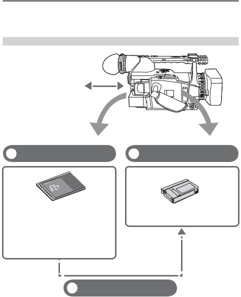
Outline of operations
This unit is compatible with P2 (Professional Plug-in) cards or DV cassette tapes.
The P2 card has a large capacity with a high transfer rate, and allows you sophisticated movie-making on this handy camera, including HD (High Definition) recording and smooth editing/dubbing.
Flow of shooting, playing and saving
The setting values such as the user file are saved to and read from the SD memory card.
1 |
P2 mode shooting and playback |
2 |
Cassette tape shooting and |
(Pages 25 and 73) |
playback (Pages 29 and 73) |
||
P2 card |
DV cassette tape |
||
You can use the following features:
•HD (High Definition) recording
•Multi format recording
•Variable frame rates
Slow & quick motion recording
•Maximum 4 channel uncompressed digital audio recording
•DV recording (480i)
•DV recording (480i)
•Dubbing mode recording from a P2 card is possible.
3 Dubbing mode (Page 86)
Dubbing mode is a function for down-converting contents recorded in HD (1080i, 720P) on the P2 card to an DV format (480i) and recording it to tape. You can record onto DV tape contents that have a slow & quick motion effect.
This is useful when backing up images and checking images on AV equipment.
•You cannot simultaneously shoot on both the P2 card and the DV cassette tape.
•High-definition (HD) recording to a DV tape is not possible.
8
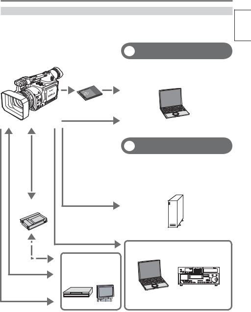
Saving and editing on external devices
Before use
4 PC mode (Page 82)
The data (file) is transferred for nonlinear editing on your computer or other unit.
P2 card
Computer
|
USB2.0 (Windows) |
|
IEEE1394 (Macintosh) |
|
5 1394 host mode (Page 84) |
|
The unit directly controls the external hard |
|
disk drive, and transfers the data (file) to it. |
|
External hard disk |
|
IEEE1394 (SBP-2 ) |
DV cassette tape |
|
|
IEEE1394 |
|
(Windows/Macintosh) |
|
Computer |
|
Memory card recorder |
|
Video equipment |
AV cable |
/Television |
|
|
Component |
|
video cable |
The contents can be transferred as a data |
|
|
|
stream (digital dubbing). |
|
Serial Bus Protocol-2 |
9

Read this first!
Always take some trial shots before actual shooting.
•When shooting important events (such as weddings), always take some trial shots and check that the sound and images have been recorded properly before actual shooting.
Be sure to check and set the calendar and time zone.
•These settings affect the control and playback sequence of the recorded contents. Before making a recording, set and check the calendar and time zone. (Page 24)
Panasonic makes no guarantees for your recordings.
•Please understand that Panasonic makes no guarantees for your recordings in cases where images and/ or sound were not recorded as you intended due to problems with the camera-recorder or cassette.
Respect copyrights
•Copyright laws forbid the use of video and audio material you have recorded for any purpose other than your own personal enjoyment. Remember that restrictions apply to the shooting of certain material even if it is intended for private use.
Caution regarding laser beams
•The CCD may be damaged if it is subjected to light from a laser beam.
When using the camera-recorder in locations where laser irradiation equipment is used, be careful not to allow the laser beam to shine directly on the lens.
Notes when connecting a DV (IEEE1394) cable
•Windows:
Before connecting, turn off the main unit power, and check the shape and orientation of the terminal.
•Macintosh:
After turning on the power of the Apple Macintosh computer, check the shape and orientation of the terminal, and then connect the cable.
(Pages 77, 78)
Media that can be used in this unit
The following media can be used in this unit. For details, refer to the respective pages.
•P2 card (Page 27)
•Digital video cassette tape (Page 30)
• SD memory card (Page 32)
Mounting the camera-recorder on a tripod
The tripod mounting hole is 5.5 mm deep. Do not force the tripod screw beyond this depth.
You can damage the camera-recorder if you use any screw other than 1/4-20UNC.
For other usage notes, see page 123.
Attach the tripod to the tripod hole
10
Accessories
Battery 1 |
AC Adapter |
AC power supply cord |
Wireless remote |
|
|
/DC cord |
control and button |
|
|
|
battery (CR2025) |
Eye cup |
Microphone holder |
6-mm screws |
(2) |
Microphone holder |
|
|
12-mm screws |
(2) |
adapter |
|
|
|
|
|
|
|
|
|
Ferrite core 2 |
|
|
|
|
|
|
|
|
|
|
Shoulder belt |
|
Component |
PIN-BNC conversion |
||||||
|
|
|
|
video cable |
cable |
(3) |
|||
|
|
|
|
|
|
|
|
|
|
|
|
|
|
|
|
|
|
|
|
|
|
|
|
|
|
|
|
|
|
|
|
|
|
|
|
|
|
|
|
|
|
|
|
|
|
|
|
|
|
Documents and CDs
Before use
A lens hood cap (page 18) and INPUT 1/2 terminal (page 14) cover are attached to the camera-recorder.
1 For part numbers for the battery, see “OPTIONAL UNITS”. (Page 132)
2 When using 1394 cable (sold separately), install a ferrite core on the end nearest the PC. (Page 78)
About this manual
Note concerning illustrations in these instructions
•Illustrations (camera-recorder, menu screens, etc.) in these operating instructions differ slightly from the actual camera-recorder.
References
• References are shown as (Page 10).
Icons
Explanations specific to the media used are identified by the icons below.
P2 : Explanations for P2 card usage only.
TAPE : Explanations for tape usage only.
11
Description of parts
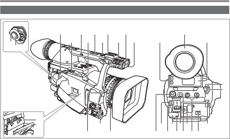
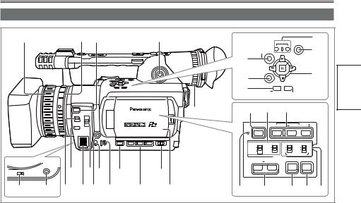
Right side and rear side
|
3 |
5 |
7 |
9 |
|
11 |
|
|
|
|
|
19 |
|
1 |
4 |
|
6 |
8 |
10 |
12 |
18 |
|
|
|
|
|
20 |
2 |
|
|
|
|
|
|
|
|
|
|
|
|
|
|
|
|
|
|
|
|
|
|
|
|
|
|
|
|
|
|
|
|
|
|
|
|
|
|
|
|
2 |
|
|
|
|
|
|
|
|
|
|
|
|
|
1 |
|
13 |
|
|
|
|
|
|
|
|
|
|
|
|
PUSH |
14 |
|
|
16 |
|
|
22 |
|
24 |
26 |
28 |
31 |
|
|
|
|
|
|
|
||||||||
|
|
|
|
|
|
|
|||||||
|
|
|
15 |
17 |
|
|
21 |
23 |
25 |
27 |
29 30 |
||
1 |
POWER switch (Page 20) |
24 |
Remote control sensor (Rear) |
2 |
START/STOP button (Pages 25 and 29) |
25 |
Tally lamp (Rear) (Page 20) |
3 |
OPEN/EJECT switch (Page 29) |
26 |
MEDIA (P2/TAPE) switch |
4 |
REC CHECK button (Pages 25 and 30) |
|
(Pages 25 and 29) |
|
|
||
5 |
HANDLE ZOOM switch (Page 33) |
27 |
EVF DTL button (Page 22) |
|
|
||
6 |
Zoom button (Page 33) |
28 |
Power terminal (Page 17) |
|
|
||
7 |
Handle zoom button (Page 33) |
29 |
AUDIO control (Page 53) |
|
|
||
8 |
Handle START/STOP button |
30 |
DC INPUT terminal (7.9 V) |
|
|
||
|
(Pages 25 and 29) |
31 |
Battery release button (Page 17) |
9 |
Pin hole (for zoom ring) (Page 13) |
|
|
10Built-in stereo microphone (Page 52)
11Tally lamp (Front) (Page 20)
12Remote control sensor (Front)
13Cassette holder (Pages 29 and 30)
14Cassette cover (Pages 29 and 30)
15White balance sensor (Page 40)
16INPUT 1/2 (audio input) switch (Page 52)
17Lens hood screw (Page 18)
18P2 card access lamp (x 2) (Page 26)
19Viewfinder (Page 21)
20P2 card slot (x 2) (Page 25)
21SCENE FILE dial (Page 54)
22Mode button (Page 25 and 29)
23Mode lamp (Page 25 and 29)
12
Left side
1 |
2 |
3 |
4 |
|
REC |
|
22 |
|
|
|
|
|
|
END SEARCH |
|||
|
|
|
|
AUDIO |
|
|
|
|
|
|
|
|
DUB/ |
|
|
23 |
|
|
|
|
|
THUMBNAIL |
|
|
||
|
|
|
|
19 |
|
|
SET |
|
|
|
|
|
20 |
|
|
|
24 |
|
|
|
|
|
|
|
|
|
|
|
|
|
21 |
MENU |
|
|
|
|
|
|
|
PAGE/ |
|
|
||
|
|
|
|
|
|
|
||
|
|
|
|
|
AUDIO MON/VAR |
|
||
|
|
|
18 |
25 |
26 |
27 |
|
|
|
|
|
|
|
|
|
|
|
|
|
|
|
BARS |
SHUTTER |
SPEED SEL |
||
|
|
|
|
RESET |
|
|
|
|
|
|
|
|
CH 1 SELECT CH 2 SELECT |
INPUT 1 |
INPUT 2 |
||
|
|
|
|
INT(L) |
INT(R) |
ON |
ON |
|
|
|
|
|
INPUT 1 |
INPUT 2 |
OFF |
OFF |
|
|
|
|
|
INPUT 2 |
|
|
|
|
|
|
|
|
|
AUDIO |
MIC POWER +48V |
||
|
|
|
|
COUNTER |
RESET/TC SET |
ZEBRA |
OIS |
|
|
|
|
AWB |
10 |
12 |
14 |
16 |
|
ZOOM |
|
8 |
||||
SERVO |
|
MANUAL |
|
|
|
|
|
5 |
6 |
7 |
9 |
11 |
13 |
15 |
17 |
28 |
29 |
30 |
31 |
32 |
Description of parts
1 Focus ring (Page 38)
2Zoom ring (Page 33)
If you don’t need the zoom ring pin, fit it into the provided pin hole (Page 12) so that you don’t lose it.
3 FOCUS ASSIST button (Page 38)
4 Built-in speaker (Page 75)
5 ZOOM switch (Page 33)
6 AWB button (Page 40)
7 FOCUS switch (Page 38)
8 PUSH AUTO button (Page 38)
9 IRIS dial (Page 39)
10ND FILTER switch (Page 39)
11IRIS button (Page 39)
12GAIN switch (Page 39)
13WHITE BAL switch (Page 40)
14DISP/MODE CHK button (Page 44)
15USER button (Page 45)
16AUTO/MANUAL switch (Pages 25 and 29)
17LCD monitor (Page 22)
18Diopter adjustment dial (Page 21)
19AUDIO DUB/THUMBNAIL button (Pages 65 and 80)
20MENU button (Page 96)
21PAGE, AUDIO MON/VAR button (Pages 46 and 73)
22REC button (Page 87)
23END SEARCH button (Page 74)
24Operation button (Page 96)
25BARS button (Page 45)
26CH1, CH2 SELECT switch (Page 52)
27SHUTTER - SPEED SEL button (Page 50)
28RESET button (Page 126)
29COUNTER - RESET/TC SET button (Page 58)
30ZEBRA button (Page 43)
31OIS button (Page 45)
32INPUT1, 2 switch (MIC POWER +48 V) (Page 52)
13
Description of parts (continued)
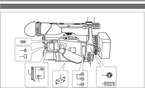
Terminals and mounting parts
1 2
3USB 2.0
4
1394
5
6 |
CAM REMOTE |
|
|
|
|
|
|
|
11 |
|
|
|
|
|
|
S-VIDEO |
|
|
|
|
|
|
|
|
ZOOM SS |
8 |
|
|
IN/OUT |
|
|
|
|
||
|
FOCUS IRIS |
9 CH1 IN/ |
|
12 |
|
|
|
|
AUDIO OUT |
|
|
|
|
|
CH2 |
|
COMPONENT |
|
7 |
|
IN/ |
|
OUT |
|
|
OUT |
|
13 |
|
|
|
10 |
|
||
|
|
|
|
VIDEO
1 Light shoe
2 Microphone shoe (Page 76)
3 USB terminal (Mini-B) (Pages 77 and 82)
4PHONES jack (3.5 mm stereo mini jack)
(Page 76)
5 1394 terminal (Page 77)
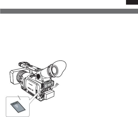
6 SD memory card slot (Pages 32 and 56)
7CAM REMOTE jack
FOCUS/IRIS (3.5 mm mini jack)
You can connect a remote control unit to control the FOCUS and IRIS (aperture).
ZOOM S/S (2.5 mm super mini jack)
You can connect a remote control unit to control zoom and start/stop of recording.
8 Tripod hole (Page 10)
9 AUDIO IN/OUT CH1/CH2 terminal (Page 79)
10VIDEO IN/OUT terminal (Page 79)
11INPUT 1/2 terminal (XLR, 3 pin) (Pages 52 and 80)
12S-VIDEO IN/OUT terminal (Page 79)
13COMPONENT OUTPUT terminal (Page 79)
Do not connect any equipment except the remote controller to the remote control jack. If any equipment except the remote controller is connected, the pictures will be affected e.g. appear bright or out of focus.
14
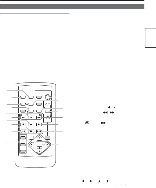
Remote control
The following buttons are for functions that cannot be executed on the camera-recorder.
• PHOTO SHOT |
• TITLE |
• MULTI/P-IN-P |
• SELECT |
• STORE |
• OFF/ON |
• PB. ZOOM |
|
|
|
|
|
1 |
|
DATE/ |
PHOTO |
|
START/ |
|
|
|
STOP |
||
2 |
OSD |
TIME |
SHOT |
|
14 |
|
|
|
|
||
|
COUNTER RESET |
TITLE |
|
4 |
|
3 |
|
ZOOM |
|||
|
|
|
|
|
|
6 |
MULTI/ |
REC |
A.DUB |
+ |
5 |
P-IN-P |
|||||
7 |
|
|
|
- VOL |
15 |
/REW |
PLAY |
FF/ |
|
|
|
|
|
|
|||
8 |
|
|
|
|
13 |
9STILL ADV PAUSE STILL ADV
12 |
10 |
10 |
INDEX STOP INDEX |
|
|
|
|
|
|
11 |
11 |
|
SELECT |
|
|
VAR. |
PB. |
|
SEARCH |
ZOOM |
16 |
STORE |
17 |
|
MENU |
OFF/ON |
SET |
|
|
P.B.DIGITAL |
ITEM |
|
1 DATE/TIME button (Page 75)
2 OSD button (Page 75)
3COUNTER button (Page 58)
Same function as the COUNTER button on the main unit.
4COUNTER RESET button (Page 58)
Same function as the COUNTER RESET button on the main unit.
5A.DUB button (Page 80)
Same function as the AUDIO DUB button on the main unit.
6 REC button (Page 87)
Used during VCR mode
7 PLAY button ( ) (Page 62)
8  /REW button (
 ) (Page 62)
9PAUSE button (
 ) (Page 62)
Like the operation buttons of the camera, MENU operations are performed using SET button.
10 |
STILL ADV button ( |
, ) (Page 73) |
|||||||
11 |
INDEX buttons ( |
|
, |
|
|
) (Page 75) |
|||
|
|
||||||||
12 |
STOP button ( |
|
) (Page 62) |
||||||
|
|||||||||
13 |
FF/ |
button ( |
) (Page 62) |
||||||
Buttons for shooting and volume control
14START/STOP button
Same function as the START/STOP button on the main unit.
15ZOOM/VOL buttons (Pages 33 and 75)
16VAR. SEARCH button (Page 73)
17MENU button
Functions the same as the MENU button on the camera.
[ ], [ ], [ ], [ ] buttons
Function the same as the ,
, ,
,  ,
,  buttons on the camera.
Description of parts
15
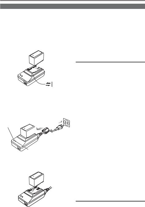
The battery
Charging
Before using the battery, fully charge it with the AC adapter.
Keep a spare battery with you.
1Align the battery with the “ ” marking on the AC adapter, place it flat, and slide it in
the direction shown below.
•You cannot charge the battery if the DC cord is connected to the DC OUT connector, so disconnect it first.
2Plug the AC cord into the power outlet.
•The POWER lamp and CHARGE lamp on the AC adapter light, and charging begins.
•If the CHARGE lamp does not light when attached, detach the battery and then attach it again.
POWER
CHARGE
3When the battery is charged, the CHARGE lamp on the AC adapter goes out.
4 Slide the battery and remove it.
Recording time of included battery
Recharging time |
Continuous recording time |
Approx. 330 min. |
Approx. 140 min. |
•The times given above are approximate for when scenes are shot in the DVCPRO HD mode on a P2 card while using the viewfinder.
•The times apply when the ambient operating temperature is 68°F (20°C) and humidity is 60%. Charging may take longer at other temperatures and humidity levels.
•Keep metal objects (such as necklaces and hairpins) away from the battery. Shortcircuiting may occur across the terminals,
causing the battery to heat up, and you may seriously burn yourself if you touch the battery in this state.
•The battery becomes hot while it is being used or charged. The camera-recorder itself also becomes hot during use.
•The recordable time reduces if you repeatedly start and stop recording.
•Discharge the battery before storing it. When storing it for an extended time, charge it at least once a year, use up its charge in the camerarecorder, and then store it again.
•If the battery is extremely hot or cold, the CHARGE lamp will blink several times before charging starts.
•If the CHARGE lamp continues to blink even when the battery temperature is normal, there may be something wrong with the battery or AC adapter. Contact your dealer.
•The battery takes longer to charge when it is warm.
•The AC adapter can interfere with radio reception so keep radios at least 1 meter away from it.
•The AC adapter may make some noise when you are using it, but this is normal.
•You cannot charge the battery when supplying power to the camera-recorder from the AC adapter.
•Operation of battery pack CGR-D16 (1600mAh) (sold separately) is not guaranteed.
16
Installing and removing the power supply
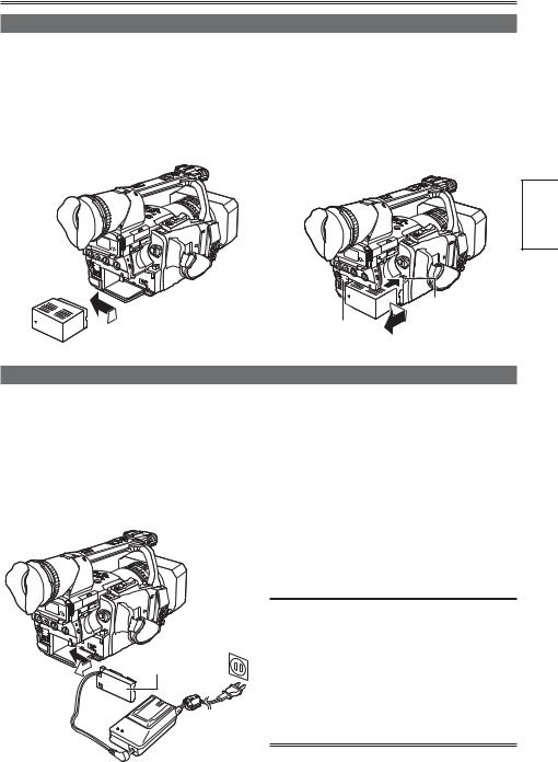
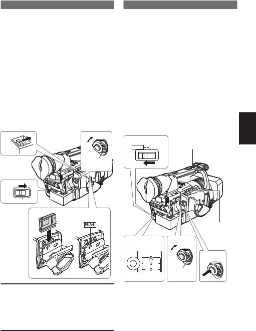
Installing and removing the battery
Installation
Insert the battery until it clicks into place.
Removal
1Set the POWER switch to OFF, and check that the mode lamp is off.
2Remove the battery while pressing the battery release button.
•Support the battery with your hand to ensure that it will not fall.
Preparation
Battery release
button
Mode lamp
Connecting and disconnecting the power cord
Installation
1 Connect the DC cord to the AC adapter.
2Plug the AC power supply into the power outlet.
3Insert the DC cord’s battery connector until it clicks into place.
DC cord’s battery connector
Removal
1Set the POWER switch to OFF, and check that the mode lamp is off.
2Remove the DC cord’s battery connector while pressing the battery release button.
3Disconnect the AC power supply cord from the power outlet.
•You cannot charge the battery when supplying power to the camera-recorder from the AC adapter.
CAUTION:
•This unit can be operated at a voltage in the range of 100-240V AC. An AC plug adapter may be required for voltages other than 120 V AC. If a conversion plug is required, consult with your dealer as to which one is to be purchased.
•Disconnect the AC power supply cord from the power outlet when the unit is not going to be used.
17

Adjusting the hand strap
Adjust the hand strap to suit your hand.
1
2
Open the cover and adjust the length.
Close the cover.
• Make sure the cover is fully closed.
Attaching the shoulder strap
Attach the shoulder strap and use it as a precaution against dropping the camera.
20 mm or more
20 mm or more
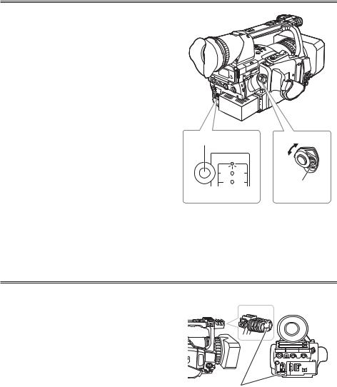
Detaching and attaching the lens hood
Detaching the lens hood
• Loosen the screw and turn the lens hood counterclockwise to detach it.
Attaching the lens hood
• Turn the lens hood clockwise and fix in position with the screw.
• Be sure to attach the lens hood cap to protect the lens when not in use.
Screw
18
The remote control
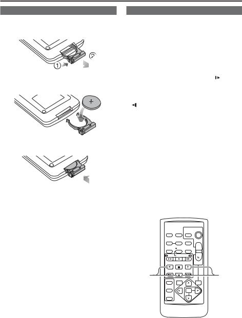
Insert the battery
1Push the catch in the direction shown by arrow (1) to remove the holder.
2Insert the battery with the “+” marked side facing up.
3 Return the holder to its original position.
•When the battery (CR2025) has run out, replace it with a new one. (The battery lasts about one year, depending on the frequency of use.)
If the remote control unit fails to work even when it is operated near the camera-recorder’s remote control sensor, the battery has run out.
•Keep the battery out of the reach of children.
Remote control setup
When using two camera-recorders simultaneously, set this camera-recorder and the remote control to either [VCR1] or [VCR2] so the remote control does not operate the wrong camera-recorder by mistake.
Setting
• Wireless remote control |
|
|
|||||
Press the STOP ( |
|
) and STILL ADV ( |
) buttons |
|
|||
|
|
||||||
at the same time to set the remote control unit for |
|
||||||
Preparation |
|||||||
control unit for use with VCR2. |
|
||||||
use with VCR1. |
|
|
|||||
Alternatively, press the STOP ( |
|
) and STILL ADV |
|
||||
( ) buttons at the same time to set the remote |
|
||||||
When the battery in the remote control unit is |
|
||||||
|
|||||||
replaced, the remote control unit is set for use |
|
||||||
with VCR1. |
|
|
|||||
• Camera |
|
|
|||||
In the setup menus, OTHER FUNCTIONS |
|
||||||
screen, REMOTE, set to VCR1 or VCR2. (Page |
|
||||||
114) |
|
|
|
|
|
|
|
If different settings are used for the camerarecorder and remote control unit, “REMOTE” lights in red on the viewfinder and LCD monitor.
|
DATE/ |
PHOTO |
START/ |
|
STOP |
||
OSD |
TIME |
SHOT |
|
COUNTER RESET |
TITLE |
ZOOM |
|
MULTI/ |
REC |
A.DUB |
+ |
P-IN-P |
|||
|
|
|
- VOL |
/REW |
PLAY |
FF/ |
|
STILL ADV |
PAUSE |
STILL ADV |
|
INDEX |
STOP |
INDEX |
|
VCR2 |
|
|
VCR1 |
SELECT |
VAR. |
|
PB. |
|
|
||
|
SEARCH |
|
ZOOM |
STORE
|
MENU |
OFF/ON |
SET |
|
|
P.B.DIGITAL |
ITEM |
|
19
Turn on/off the camera
While pressing the lock release, move the POWER switch to ON or OFF.
Turn on the camera:
The mode lamp (CAMERA) lights red (CAMERA mode) and the camera is now in the shooting standby mode.
Turn off the camera:
The red mode lamp goes out.
•Power saving mode
The camera-recorder performs as follows when you pause or leave it in standby mode for about 5 minutes, and do not perform any specified operations.
ON: The camera recorder turns off automatically OFF: Do not switch OFF the camera. In the TAPE
mode, however, put the cylinder head alone in a stopped (standby) status.
See the setup menus, OTHER FUNCTIONS screen, POWER SAVE (page 117) for details.
•When the operation mode buttons flash in sequence starting with the top one and the power then goes off, it means that there is no charge left in the battery. Recharge the battery.
Mode button |
|
ON |
|
|
|
CAMERA |
OFF |
|
|
|
|
MCR |
VCR |
|
PC |
DUB |
Lock release |
|
|
|
Mode lamp
Tally lamp
The tally lamp can be made to light up during shooting by selecting “ON” as the REC LAMP set-ting in the OTHER FUNCTIONS screen. (Page 115)
When the camera-recorder is in any of the following states, the tally lamp blinks.
•When an operation initiated by the remote control unit has been received (8 blinks/sec.)
• When shooting starts in the TAPE mode (8 blinks/ |
|
|
sec.) |
|
|
• When the end of the tape is reached (4 blinks/ |
Tally lamp |
|
sec.) |
||
|
•When trouble occurs regarding tape running systems (4 blinks/sec.)
•When the remaining battery capacity runs out (4 blinks/sec.)
•When the available recording space on the P2 card or tape or the battery power is low (1 blinks/ sec.)
•When removing the P2 card during access (4 blinks/sec.)
•When there is no recording space left on the P2 card (4 blinks/sec.)
20
Viewfinder
This camera has two viewfinders; one is a miniature LCD in the viewfinder and the other is a retractable 3.5-inch LCD.
Use the viewfinder that best suits the application and shooting conditions.
•The brightness and hue may differ between the images appearing on the viewfinder and LCD monitor and those displayed on a TV monitor. To see how the final images will appear, check them on a TV monitor.
Using the viewfinder
1Set the POWER switch to ON and check that images appear in the viewfinder.
• Keep the LCD monitor closed.
ON
Fitting the eye cup
Attach the eye cup by aligning the projections on the eye cup holder and eye cup and fitting them together.
•Turning the eye cup after attaching it may cause the eye cup holder to come off. If the eyecup holder does come off, see “Cleaning the Viewfinder” (page 126) for details on how to refit it.
Eye cup holder
Eye cup
2 Adjust the viewfinder’s angle so that the |
Projection |
screen is positioned where it is easiest to |
|
|
|
see. |
|
•You can move the view finder out to about 90° perpendicular to the camera.
3Adjust the diopter adjustment lever so that you can see the characters on the viewfinder screen clearly.
Viewfinder diopter dial
Eye piece
Preparation
Do not point the eye piece at the sun.
Doing so may damage the parts inside.
21
Viewfinder (continued)
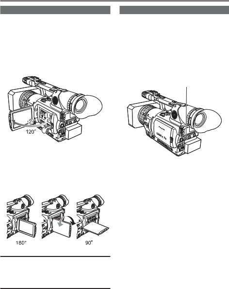
Using the LCD
1 Set the POWER switch to ON.
2Press the OPEN button in the direction shown by arrow (1) to open the LCD.
It can open out to 120 degrees. Do not try to open it further as this will damage the camera.
3Position the LCD monitor where it is easiest to see.
•The monitor can be rotated 180° toward the lens and 90° toward you.
•Do not apply unnecessary force to the open LCD. This can damage the camera.
•Ensure the LCD is fully closed.
•Both the LCD and viewfinder come on when you have rotated the LCD to face in the same direction as the lens for self-portrait shooting.
Emphasizing outlines
Emphasizing the outlines of the images you see in the viewfinder or on the LCD makes it easier to focus.
Emphasizing the outlines does not effect the images you shoot.
1In CAMERA mode, press EVF DTL.
•“EVF DTL ON” appears on the screen for about 2 seconds.
EVF DTL button
Press EVF DTL again to return to the original display. “EVF DTL OFF” appears on the screen for about 2 seconds.
22
Adjusting the screen display
1 Set the POWER switch to ON. (Page 20)
2 Press the MENU button.
SET
Operation button
MENU
•For menu operation (Page 96)
•You can also use the menu buttons on the remote control. (Page 15)
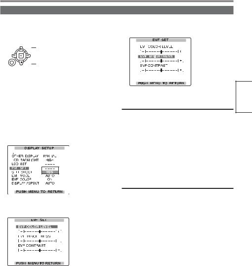
3Viewfinder adjustments
Set YES under EVF SET on the setting menu DISPLAY SETUP screen.
LCD monitor adjustments
Set YES under LCD SET on the setting menu DISPLAY SETUP screen.
4Select the item to be set using the  or
or  operation button.
5Adjust the selected item using the  or
or  operation button.
6 Press MENU three times to exit the menus.
•You can return the settings for EVF SET and LCD SET to the factory settings by selecting the item and pressing COUNTER RESET (if it is possible to change the item at that time).
•The viewfinder remains on when you open the LCD if you have set the EVF MODE in the DISPLAY SETUP screen to ON.
•The viewfinder display can be in color or black and white. (See the setup menus, DISPLAY SETUP screen, EVF COLOR.) The resolution is the same for both of them.
Preparation
23
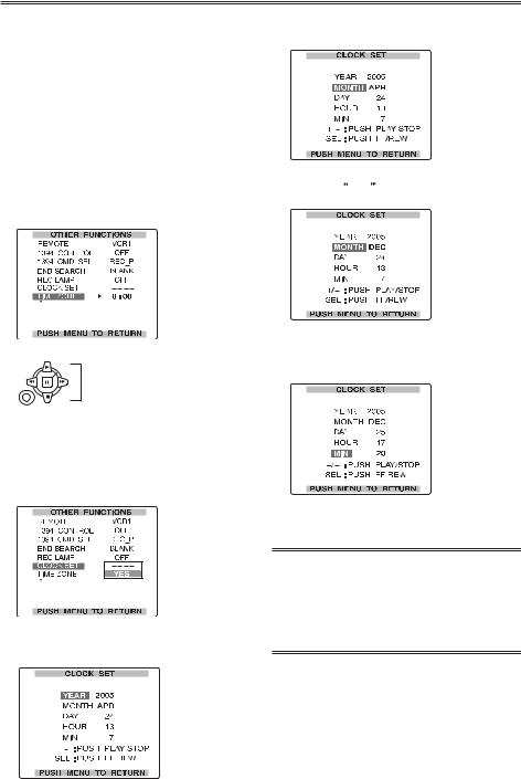
Setting the calendar
The CLOCK SET value is recorded in the contents (clip), and affects the sequence of playback of the thumbnails. Before carrying out recording, be sure to check and set CLOCK SET and TIME ZONE.
This shows you how to adjust the calendar to 5:20 PM on December 25, 2005.
1 Set the POWER switch to ON. (Page 20)
2 Press the MENU button.
3In the setup menus, OTHER FUNCTIONS screen, TIME ZONE, set the time difference from Greenwich mean time using the  or
or  operation button. (Page 116)
(Example of MENU in the TAPE mode)
SET
Operation button
MENU
•For menu operation (Page 96)
•You can also use the menu buttons on the remote control. (Page 15)
4In the setup menus, OTHER FUNCTIONS screen, CLOCK SET, select YES.
5Press the  or
or  operation button to set YEAR to 2005.
Choose a year between 2000 and 2030.
6Press the  operation button to move the setting item to MONTH.
7Press the  or
or  operation button to set MONTH to DEC.
8Set DAY, HOUR, and MIN using the method shown in steps 4 and 5.
• This is a 24-hour clock.
9 Press MENU three times to exit the menus.
•The clock can vary in accuracy so check that the time is correct before shooting.
•When using the camera overseas, do not set the CLOCK option to the current time, but instead enter the time difference from Greenwich mean time according to TIME ZONE.
24
Basic shooting operations (P2 card) |
P2 |
|
|
|
|
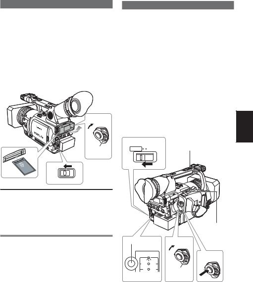
Preparing to shoot using a P2 card
1 Switch the MEDIA switch to “P2”.
2 Set the POWER switch to ON. (Page 20)
3Lift up the viewfinder and open the card slot cover.
4Insert the P2 card securely in the card slot.
•There are two card slots.
•Be absolutely sure to close the card slot covers to keep the dust out.
Shooting in auto mode
1Turn the POWER switch to ON. (Page 20)
•Check that the mode lamp (CAMERA) is lighted red. If not, press the mode button.
2Switch the AUTO/MANUAL switch to AUTO to select auto mode.
•“A” appears on the viewfinder and LCD screens.
•The focus, gain, iris and white balance are adjusted automatically.
|
2 |
|
|
ON |
|
|
3 |
|
4 |
Lock |
|
release |
||
|
1
P2 
 TAPE
TAPE
Do not operate the MEDIA switch when the power is switched ON.
If you attempt to operate the MEDIA switch, the message “TURN POWER OFF” will be displayed. In this case, switch OFF the power, and then switch it ON again.
3Press the START/STOP button (Red) on the POWER switch to start shooting.
•Press again to return to the camera to the shooting standby mode.
•Use the handle START/STOP button to make it easier to shoot from low angles.
2 LCD side |
Handle START/STOP |
AUTO MANUAL |
button |
REC CHECK button
Mode button |
1 |
ON |
|
|
|
||
CAMERA |
|
3 |
|
|
|
||
MCR |
VCR |
|
|
PC |
DUB |
Lock |
|
|
|
||
Mode lamp release
Shooting
25
Basic shooting operations (P2 card) (continued) |
P2 |
Checking photos taken (REC CHECK)
In the shooting pause mode, press the REC
CHECK button.
A few seconds of the last thing you shot play.
•Note that this REC CHECK portion will also be recorded to any equipment you have set up to make backup recordings.
•Only the POWER and START/STOP buttons are operable during REC CHECK.
•The REC CHECK function does not work when PC, MCR or DUB has been selected as the operation mode.
The HD recording(720P/60P) settings are already made in the default mode.
(To view the current settings, see page 44.)
P2 card access lamps
CAMERA mode (MCR)
Lights green: Data can be saved onto the cards or loaded from them.
Blinks green (slow): No available space on card, card is write-protected
Lights orange: Slot that is the object of recording Blinks orange : Data is now being accessed.
Blinks orange (fast): A card is now being recognized.
Both lamps blink orange: Ejection of card during access
Off: Cards have not been inserted or formatted. Insertion of incompatible card.
PC mode (USB DEVICE)
Blinks orange: Data is now being accessed. Off: A status other than access underway.
PC mode (1394 DEVICE)
Blinks orange: Connected
Off: Not connected
PC mode (1394 HOST) Lights green: Access standby.
Blinks orange: Data is now being accessed. Off: Cards have not been inserted or formatted.
Insertion of incompatible card.
P2 card access lamp
Protecting against a possible erasure
Switch the write-protect switch of the P2 card to [PROTECT].
Write-protect switch
PROTECT
26
P2
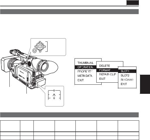
Formatting P2 cards
1Press the mode button and set it to MCR mode (the MCR/VCR lamp lights).
• Thumbnails are displayed.
2 Press the MENU button.
SET
Operation button
MENU
3On the menu, select OPERATION and then FORMAT.
•A screen such as the one shown below appears. Select the number of the slot into which you inserted the P2 card to be formatted. Select EXIT to cancel the formatting.
•When you press the MENU button, the menu display disappears.
MENU button |
|
|
CAMERA |
|
|
|
|
||
|
|
|
|
4 Select YES on the confirmation screen. |
|||||
Mode button |
MCR |
VCR |
|||||||
|
|
|
|
||||||
PC |
DUB |
|
• The selected P2 card is formatted. |
||||||
|
|
|
|
||||||
|
|
|
Mode lamp |
|
|
|
|
||
Recording times |
|
|
|
|
|
|
|
||
|
|
|
DVCPRO |
DVCPRO50 |
DVCPRO HD 1 |
DVCPRO HD |
DVCPRO HD |
||
Card model |
Capacity |
|
2-channel |
4-channel |
|
||||
|
|
|
audio |
audio |
|
|
720P/24PN |
720P/30PN |
|
|
|
|
|
|
|
|
|||
AJ-P2C004HG |
4 GB |
approx. 16 min. |
approx. 8 min. |
approx. 4 min. |
approx. 10 min. |
approx. 8 min. |
|||
AJ-P2C008HG |
8 GB |
approx. 32 min. |
approx. 16 min. |
approx. 8 min. |
approx. 20 min. |
approx. 16 min. |
|||
•The AJ-P2C002SG (2 GB) card cannot be used.
•The displayed available space includes the management area, and so the space available for recording is smaller than this.
•Concerning the division of clips recorded on P2 cards
When using a P2 card of at least 8 GB in this camera, if the continuous recording time for a single session exceeds the time shown in the following table, recording will be automatically resumed as a different clip. When performing a thumbnail operation (display, delete, restore, copy, etc.) on clips using P2 cards, you can operate them as a single clip. When you are using non-linear editing software and a PC, for example, the clips are displayed individually.
Recording Format |
Recording times |
|
|
|
|
|
|
DVPRO HD 1 |
approx. 5 min. |
|
|
DVPRO50 |
approx. 10 min. |
*1 The 720P/30PN and 720P/24PN formats are not |
|
|
|
||
DVPRO/DV |
approx. 20 min. |
||
included in the DVCPRO HD recording format. |
|||
|
|
•When using any other types of cards, the driver installed in the camera-recorder may need to be updated. (Page 125)
•For the latest information not available in the Operating Instructions, visit the P2 Support Desk at the following Web sites.
https://eww.pavc.panasonic.co.jp/pro-av/
Shooting
27
Basic shooting operations (P2 card) (continued) |
P2 |
|
|
|
|
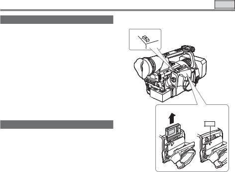
Remove the P2 card
1Lift up the viewfinder and open the card slot cover.
•Check that the P2 card access lamp is not blinking orange.
2Press the card eject button once, and when the button has popped back up, press it again.
3 Remove the P2 card.
1
Card eject button
 2
2
 3
3
•Do not eject a P2 card while its data is being accessed or while it is being recognized after insertion (the P2 card access lamp is blinking orange).
•If a P2 card is ejected during formatting or while its data is being accessed, “TURN POWER OFF” appears in the viewfinder, and a warning is indicated by an alarm or tally lamp. If this happens, turn the power off and back on again.
When a card is ejected during formatting:
Format the card again.
When a card is ejected while its data is being accessed:
The data on the card will not be destroyed, but the clips may be thrown out of order. Check the clips and repair them. (For details on repairing clips, see page 69.)
•During playback, a P2 card inserted into the empty slot will not be recognized and the P2 card access lamp will not light. When playback is completed, the P2 card recognition will begin.
•You can use ACCESS LED on the OTHER FUNCTIONS screen to set the P2 card access lamps so that they will always be off. In this case, either turn off the power or wait until enough time has passed after inserting the cards or stopping operation before ejecting the cards.
•If a P2 card is ejected while thumbnails are displayed, the thumbnail screen is released.
28
Basic shooting operations (Cassette tape) |
TAPE |
|
|
|
|
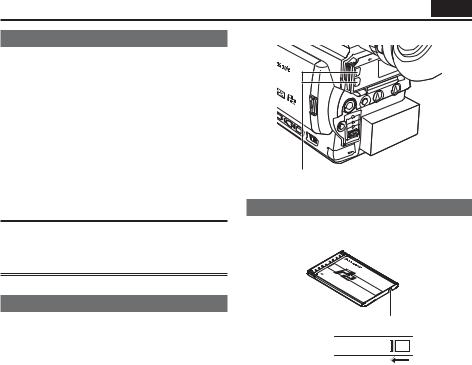
Preparing to shoot using a tape
1 Switch the MEDIA switch to “TAPE”.
2 Set the POWER switch to ON. (Page 20)
3Slide the OPEN/EJECT switch in the direction shown by the arrow to open the cassette cover.
•The cassette holder opens automatically.
•The cassette holder will not open if the camera is not supplied with power (AC adapter or a battery).
4 Insert the cassette tape.
5Press PUSH to close the cassette holder.
•Close the cassette cover only after the cassette holder is completely in position.
3 |
2 ON |
Lock |
release |
1
P2 TAPE
TAPE
4 |
5 |
PUSH |
PUSH |
|
Shooting in auto mode
1Turn the POWER switch to ON. (Page 20)
•Check that the mode lamp (CAMERA) is lighted red. If not, press the mode button.
2Switch the AUTO/MANUAL switch to AUTO to select auto mode.
•“A” appears on the viewfinder and LCD screens.
•The focus, gain, iris and white balance are adjusted automatically.
3Press the START/STOP button (Red) on the POWER switch to start shooting.
•Press again to return to the camera to the shooting standby mode.
•Use the handle START/STOP button to make it easier to shoot from low angles.
2 LCD side |
Handle START/STOP |
AUTO MANUAL |
button |
|
|
REC CHECK |
|
|
button |
Mode button |
1 ON |
|
|
|
|
CAMERA |
3 |
|
|
|
|
MCR |
VCR |
|
PC |
DUB |
Lock |
|
|
|
Mode lamp |
release |
|
Do not operate the MEDIA switch when the power is switched ON.
If you attempt to operate the MEDIA switch, the message “TURN POWER OFF” will be displayed. In this case, switch OFF the power, and then switch it ON again.
Shooting
29
Basic shooting operations (Cassette tape) (continued)
Checking scenes taken (REC CHECK)
In the shooting pause mode, press the REC CHECK button.
A few seconds of the last thing you shot play, and then the camera returns to the shooting pause mode.
•The REC CHECK function cannot be used unless the recording is at least one second long.
•When recording backup images by connecting the equipments using a 1394 cable, the images will not appear during REC CHECK.
•The REC CHECK function does not work when VCR or DUB has been selected as the operation mode.
Remove the cassette tape
1 Slide the OPEN/EJECT switch in the
1 
2
PUSH
direction shown by the arrow to open the cassette cover.
•The cassette holder opens automatically.
•The cassette holder will not open if the camera is not supplied with power (AC adapter or battery).
•A tape cannot be ejected in P2 mode or during recording in TAPE mode.
2 Remove the cassette.
3Press PUSH to close the cassette holder.
•Close the cassette cover only after the cassette holder is completely in position.
TAPE
3
PUSH
PUSH
30
 Loading...