


Outback Power Systems FX2024ET, VFX3048E, VFX2612E, VFX3024E, FX2348ET User Manual
...International
FX and VFX Series
INVERTER/CHARGER
Programming Manual
WARRANTY SUMMARY
Dear OutBack Customer,
Thank you for your purchase of OutBack products. We make every effort to assure our power conversion products will give you long and reliable service for your renewable energy system.
As with any manufactured device, repairs might be needed due to damage, inappropriate use, or unintentional defect. Please note the following guidelines regarding warranty service of OutBack products:
•Any and all warranty repairs must conform to the terms of the warranty.
•All OutBack equipment must be installed according to their accompanying instructions and manuals with specified over-current protection in order to maintain their warranties.
•The customer must return the component(s) to OutBack, securely packaged, properly addressed, and shipping paid. We recommend insuring your package when shipping. Packages that are not securely packaged can sustain additional damage not covered by the warranty or can void warranty repairs.
•There is no allowance or reimbursement for an installer’s or user’s labor or travel time required to disconnect, service, or reinstall the damaged component(s).
•OutBack will ship the repaired or replacement component(s) prepaid to addresses in the continental United States, where applicable. Shipments outside the U.S. will be sent freight collect.
•In the event of a product malfunction, OutBack cannot bear any responsibility for consequential losses, expenses, or damage to other components.
•Please read the full warranty at the end of this manual for more information.
About Outback Power Systems
OutBack Power Systems is a leader in advanced energy conversion technology. Our products include true sine wave inverter/chargers, maximum power point charge controllers, system communication components, as well as breaker panels, breakers, accessories, and assembled systems.
Notice of Copyright
International FX and VFX Series Inverter/Charger Programming Manual © 2007 All rights reserved.
Disclaimer
UNLESS SPECIFICALLY AGREED TO IN WRITING, OUTBACK POWER SYSTEMS:
(a)MAKES NO WARRANTY AS TO THE ACCURACY, SUFFICIENCY OR SUITABILITY OF ANY TECHNICAL OR OTHER INFORMATION PROVIDED IN ITS MANUALS OR OTHER DOCUMENTATION.
(b)ASSUMES NO RESPONSIBILITY OR LIABILITY FOR LOSS OR DAMAGE, WHETHER DIRECT, INDIRECT, CONSEQUENTIAL OR INCIDENTAL, WHICH MIGHT ARISE OUT OF THE USE OF SUCH INFORMATION. THE USE OF ANY SUCH INFORMATION WILL BE ENTIRELY AT THE USER’S RISK.
Contact Information:
OutBack Power Systems
19009 62nd Ave. NE
Arlington, WA 98223 Phone (360)435-6030 • Fax (360)435-6019 www.outbackpower.com
Date and Revision • July 2008 REV C
1
TABLE OF CONTENTS |
|
Warranty Summary..................................................................................................................................................................................... |
1 |
Declaration of Conformity ..................................................................................................................................................................... |
3 |
Welcome to the OutBack Power Systems FX Series Inverter/Charger System ..................................................... |
4 |
Safety......................................................................................................................................................................................................... |
4 |
Modes and Properties .............................................................................................................................................................................. |
5 |
Set-Up Screens.............................................................................................................................................................................................. |
5 |
Search Mode .................................................................................................................................................................................................. |
6 |
Input Menu ..................................................................................................................................................................................................... |
7 |
Advanced Screens ...................................................................................................................................................................................... |
9 |
Inverter Menu............................................................................................................................................................................................. |
10 |
Charger Menu............................................................................................................................................................................................. |
13 |
Generator Menu........................................................................................................................................................................................ |
16 |
FX Series Inverter/Charger Programming................................................................................................................................. |
19 |
Components and Connections....................................................................................................................................................... |
20 |
Stacking Options ...................................................................................................................................................................................... |
23 |
OutBack Parallel................................................................................................................................................................................ |
23 |
3-Phase.................................................................................................................................................................................................. |
24 |
Stacking And Assigning FX Status ................................................................................................................................................. |
24 |
1-2ph Master..................................................................................................................................................................................... |
24 |
Classic Slave........................................................................................................................................................................................ |
25 |
OB Slave L1.......................................................................................................................................................................................... |
25 |
3ph Master........................................................................................................................................................................................... |
25 |
3ph Slave.............................................................................................................................................................................................. |
25 |
Programming the FXs............................................................................................................................................................................ |
26 |
1-2 ph Master..................................................................................................................................................................................... |
29 |
OutBack (OB) Slave......................................................................................................................................................................... |
29 |
OutBack (OB) Slave 2..................................................................................................................................................................... |
30 |
3-Phase (3ph) Master.................................................................................................................................................................... |
30 |
3-Phase (3-ph) Slave...................................................................................................................................................................... |
31 |
Introduction to Power Save Levels................................................................................................................................................ |
32 |
Powering Up................................................................................................................................................................................................ |
34 |
Stacking System Examples................................................................................................................................................................. |
36 |
OutBack Parallel Stacking........................................................................................................................................................... |
36 |
Ranking the Slaves ............................................................................................................................................................... |
37 |
3-Phase Stacking ................................................................................................................................................................... |
39 |
Auxiliary (AUX) Functions.................................................................................................................................................................... |
40 |
List of AUX Functions.................................................................................................................................................................... |
43 |
Adjustable AUX Output Functions....................................................................................................................................... |
43 |
Battery Charging Function ................................................................................................................................................................. |
46 |
Maintenance ............................................................................................................................................................................................... |
46 |
Battery Charging Instructions........................................................................................................................................................... |
47 |
FX Default Values...................................................................................................................................................................................... |
50 |
Warranty......................................................................................................................................................................................................... |
51 |
Product Registration............................................................................................................................................................................... |
53 |
2
DECLARATION OF CONFORMITY
The OutBack Power Systems FX Series Inverter/Chargers export (“E”) models comply with the EU Declaration of Conformity regarding Electromagnetic Compatibility 89/336/EEC (“Council Directive of 3 May 1989”) and Low Voltage Directive 73/23/EEC (“Council Directive of 19 February 1973”) when installed in off-grid applications only. These inverter/chargers are not to be connected to the mains under any circumstances.
The AC-IN connection on each E model inverter/charger is only approved for connection to an AC generator.
FX Series Inverter/Chargers covered by the EU Declaration of Conformity:
•FX2012ET
•FX2024ET
•FX2348ET
•VFX2612E
•VFX3024E
•VFX3048E
3

WELCOME TO THE OUTBACK POWER SYSTEMS FX SERIES
INVERTER/CHARGER SYSTEM
The FX and VFX Series Inverter/Charger offers a complete power conversion system—DC to AC, battery charging, and an AC internal transfer relay—for stand-alone applications.
OutBack Power Systems does everything possible to assure the components you purchase will function properly and safely when installed as instructed according to local and national electrical codes. Please read all of the following instructions and the instructions that come with any OutBack components included in your power system. Further instructions on individual FX set-ups as well as systems assemblies are included with the International FX and VFX Series Inverter/Charger Installation Manual.
The OutBack Power Systems FX and VFX is ETL listed to UL1741 (Inverters, Converters, Controllers, and Interconnection System Equipment for Use with Distributed Energy Resources). All Mobile FX Series Inverter/Chargers are ETL listed to UL 458.
Grounding Instructions
Each FX should be connected to a grounded, permanent wiring system. For most installations, the negative battery conductor should be bonded to the grounding system at one (and only one) point in the DC system. All installations must comply with all national and local codes and ordinances.
The equipment ground is marked with this symbol:
The International FX and VFX Series Inverter/Charger Programming Manual covers the following information:
•Safety
•Programming or “stacking” multiple FXs using the OutBack Power Systems MATE
•Explaining the FX modes and properties.
IMPORTANT SAFETY INSTRUCTIONS
KEEP THESE INSTRUCTIONS
General Precautions
1.Use caution whenever working around electricity, electrical components, and batteries. There is always a potential for shocks, burns, injury, and even death if an installer or user comes in contact with electricity.
2.Read all instructions and cautionary markings on the FX, the batteries and all appropriate sections of this manual as well as other component manuals before using the system.
3.Be sure each system FX is securely installed according to the International FX and VFX Series Inverter/ Charger Installation Manual.
4.Follow all local and national electrical codes when installing OutBack equipment and components.
4
FX MODES AND PROPERTIES
Each OutBack FX and VFX comes with various default values set at the factory. Typically, a single FX in-
stallation will retain these values, but multiple FXs will require programming using the OutBack MATE.
Viewing the status of an FX and adjusting its functions also requires a MATE.
The OutBack MATE is a system controller and display which shows operational
status via a lighted screen. It allows a user to change function settings such
as battery charging and generator usage using a series of buttons (“soft “ keys
and “hot” keys).
MATE
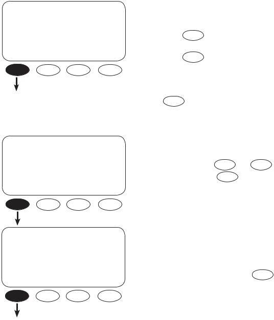
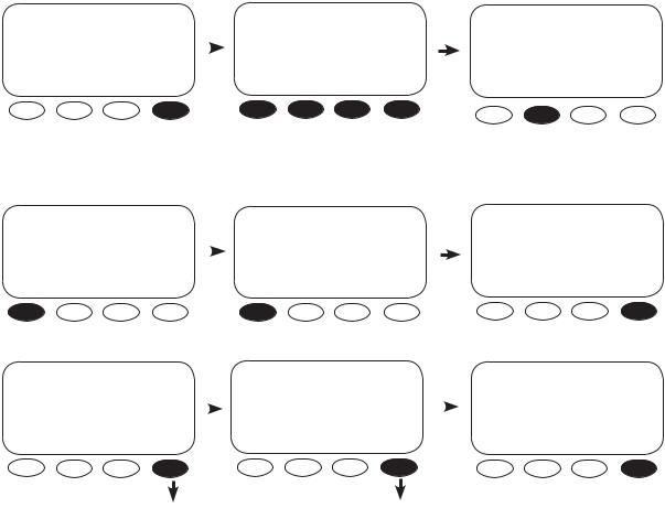
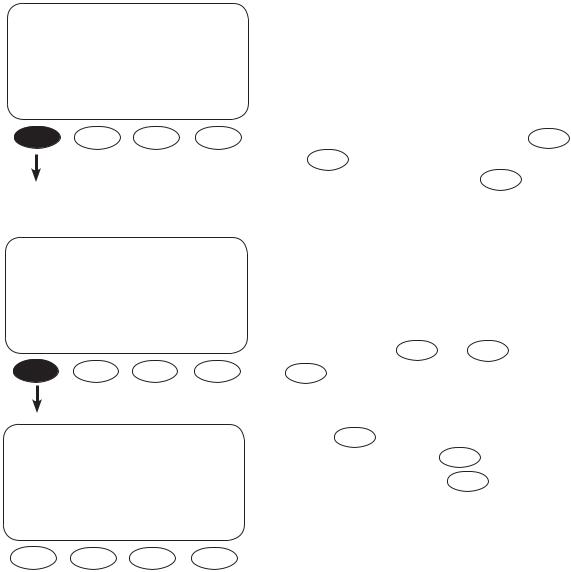
SETUP SCREENS
MAIN--------------------------
12:12:16A
SUM STATUS SETUP ADV
SETUP------------------------------
choose product:
FX MATE
SETUP/FX--------------------------
choose category:
SRCH INPUT MAIN
From the MAIN screen, press SETUP
NOTE: Pressing and holding the first two soft keys at the same time will always bring up the MAIN Menu screen. The SUM and STATUS screens are displayed and explained in the MATE Installation and User Manual.
Press FX
Two choices are available in the choose category
screen:
•Search (SRCH) which adjusts the search mode settings
•INPUT which for selecting the AC INPUT and current limit adjustment
Press SRCH to open the search screens.
5
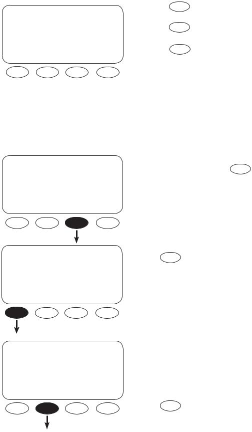
SEARCH MODE
An FX consumes a small amount of power when it is not providing AC to loads or recharging batteries. In SEARCH MODE, the FX is inactive and conserves power until it senses a user-determined size load. The FX then turns on to provide AC to that load. The SEARCH features are mainly used in offgrid systems to conserve power.
NOTE: Some loads will require experimenting with the SEARCH settings and other loads, such as fluorescent lights with magnetic ballasts, might not work well at all.
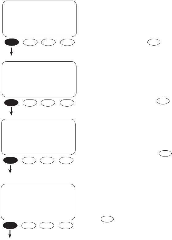
SETUP/FX/SEARCH-------- |
P00 |
search |
6 |
sensitivity |
|
DOWN INC DEC |
PORT |
SETUP/FX/SEARCH-------- |
P00 |
search |
8 cycles |
pulse length |
|
DOWN INC DEC |
PORT |
SETUP/FX/SEARCH-------- |
P00 |
search |
60 cycles |
pulse spacing |
|
DOWN INC DEC |
PORT |
Use the search sensitivity screen to determine the size of an AC load needed for the FX to turn ON and leave SEARCH mode.
• Pressing |
INC decreases sensitivity (a bigger |
load is needed to turn the FX on) |
|
• Pressing |
DEC increases the sensitivity which |
means a smaller load (less wattage) will turn |
|
the FX on |
|
• Decreasing to zero disables SEARCH mode |
|
Press DOWN |
to view the next SEARCH screen. |
The FX produces pulses to detect AC loads. The search pulse length screen allows adjusting the number of pulses (from 2 to 20) or cycles to
more reliably detect AC loads. A setting of 8 or
higher, adjusted using |
INC |
and DEC , |
is recommended. Press |
DOWN |
to open the |
search pulse spacing screen. |
|
|
The search pulse spacing screen adjusts the amount of time the FX waits before producing additional AC pulses to sense a load. The higher the number of cycles, the lower the FX power consumption, but the longer it takes before the AC load is powered. The cycles range from 4 to 120 cycles (two seconds). Press the DOWN to complete the SEARCH menu.
6
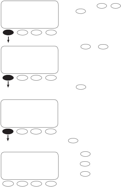
SETUP/FX/SEARCH------------- |
Pressing |
TOP |
returns you to the SETUP/FX/ |
SEARCH screen. |
|
||
search setup |
Pressing |
SETUP |
returns the user to the choose |
completed |
category screen. |
|
|
|
|
||
TOP SETUP MAIN |
Pressing |
MAIN |
returns to the MAIN Menu. |
|
|
|
|
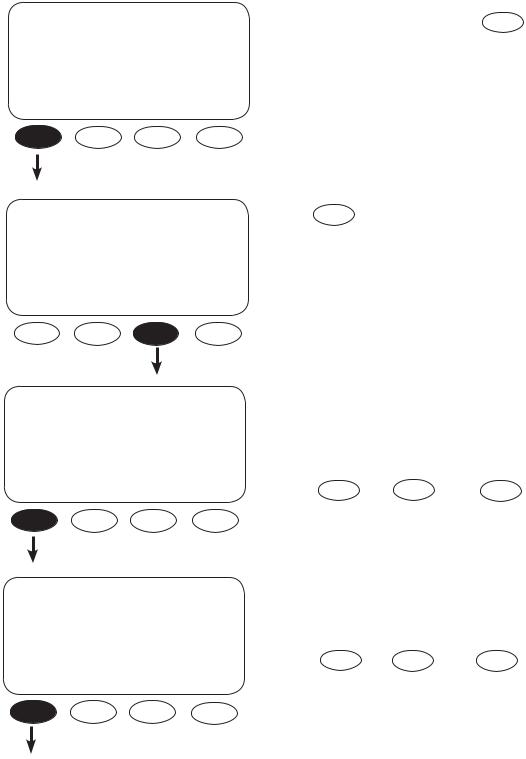
INPUT MENU
The INPUT screens allow the user to choose either grid or generator AC input and the maximum amperage from either source that can pass through the FX before a warning occurs.
MAIN-------------------------- |
From the MAIN screen, press |
SETUP |
. |
|
|
|
12:12:16A
SUM STATUS SETUP ADV
SETUP |
Press FX . |
|
|
choose product: |
|
FX |
MATE |
SETUP/FX---------------------------
choose category:
SRCH INPUT MAIN
Two choices are available in the choose category screen:
•Search (SRCH) adjusts the search mode settings
•INPUT selects the AC INPUT and current limit adjustment
Press INPUT .
7
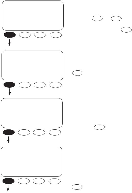
SETUP/FX/INPUT---------- |
P00 |
ac transfer |
Gen |
control |
|
DOWN GRID GEN |
PORT |
SETUP/FX/INPUT---------- |
P00 |
|
ac1/grid |
|
24.5 aac |
limit |
|
|
DOWN INC |
DEC |
PORT |
SETUP/FX/INPUT---------- |
P00 |
|
ac2/gen |
|
30.0 aac |
limit |
|
|
DOWN INC |
DEC |
PORT |
SETUP/FX/INPUT----------------
input setup completed
TOP SETUP MAIN
To choose your AC input source in the ac transfer control screen, press GRID or GEN .
Press DOWN to view the next screen.
By using INC and DEC , the ac1/grid menu sets the maximum current the FX will allow to be drawn from the grid by either AC loads and/or the batteries (during recharging). When this limit is exceeded, an AC input limit warning appears and the FX will reduce the almount of charging so that the total current draw does not exceed the maximum setting (between 2.5AAC and 30.0AAC). Press DOWN to view the next INPUT screen.
The ac2/gen limit screen sets the maximum current the FX will allow to be drawn from a generator by either AC loads or the batteries (during recharging). When this limit is exceeded, the FX will reduce the amount of charging current so the total current draw does not exceed the maximum setting (between 1.0AAC and 30.0 AAC) to avoid damage to the generator. Press the DOWN to view the final INPUT screen.
Pressing |
TOP |
returns you to the SETUP/FX/ |
SEARCH screen. |
|
|
Pressing |
SETUP |
returns the user to the choose |
category screen. |
|
|
Pressing |
MAIN |
returns to the MAIN Menu. |
.
8
ADVANCED SCREENS
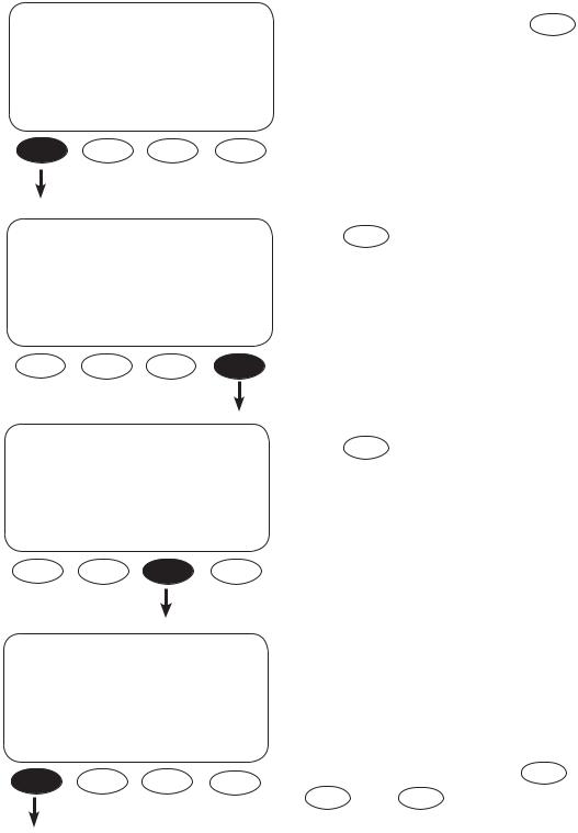
All the FX operation settings can be adjusted in the MATE’s ADVANCED screens, including some previously discussed in the INPUT and SETUP menus. Changing the settings under any menu will affect the values in all menus. The ADVANCED screens are accessed via the password 141.
MAIN |
-------------------------- |
|
ADV/SETTINGS/WARNING |
|
|
|
|
|
12:12:16A |
|
changes made could adversely affect |
|
|
||
|
|
|
|
|
|
|
system performance |
ADV/PASSWORD----------------
enter the password
132
SUM STATUS SETUP ADV
Push any soft key on the ADV/ SETTINGS/WARNING screen and go to the ADV/PASSWORD screen.
ADV/PASSWORD---------------- |
|
ADV |
|
|
enter the password |
|
choose device: |
|
|
141 |
|
FX |
CC |
DC MATE |
|
||||
ENTER INC DEC EXIT |
|
|||
ENTER INC DEC EXIT
The screen displays <132>. Press the <INC> button until it scrolls to the password 141.
ADV/FX/PAGE 1-----------------
choose category:
ADV INV CHGR PG2
ADV/FX/PG2--------------------- |
|
ADV/FX/PAGE3------------------ |
|
ADV/FX/PAGE4------------------ |
|
choose category: |
|
choose category: |
|
choose category: |
|
PG1 GRID GEN PG3 |
|
PG2 AUX STACK PG4 |
|
PG3 SELL CAL |
MAIN |
|
|
Pressing the <MAIN> soft key will display the MAIN screen.
The FX settings and their adjustments include:
•INV—INVERTER
•CHGR—CHARGER
•GRID—AC input if the FX input is set to GRID
•GEN—AC input if the FX input is set to GEN
•AUX—AUX OUTPUT
•STACK—Master and Slave designations when multiple FXs are in use
•SELL—Grid-Interactive FX operations
•CAL—Adjusts voltage calibration measurements for improved operation
9
INVERTER MENU
The INVERTER screens allow adjusting the inverter’s operations to match the AC load and battery recharging requirements, including the search functions, low-battery cut-out, the FX’s output voltage, and resetting the FX to its factory default values.
ADV |
After entering the ADVANCED screens, |
||
press |
FX on the choose device screen. |
||
choose device: |
|||
|
|
||
FX CC DC MATE
ADV/FX/PAGE 1-----------------
Press INV .
choose category:
ADV INV CHGR PG2
ADV/FX/INVERTER------- |
P00 |
search |
6 |
sensitivity |
|
DOWN INC DEC |
PORT |
ADV/FX/INVERTER------- |
P00 |
search |
8 cycles |
pulse length |
|
DOWN INC DEC |
PORT |
Use the search sensitivity screen to determine the size of an AC load needed for the FX to turn ON and leave SEARCH mode.
• Pressing |
INC decreases sensitivity (a bigger |
load is needed to turn the FX on) |
|
• Pressing |
DEC increases the sensitivity |
which means a smaller load (less wattage) will turn the FX on
•Decreasing to zero disables SEARCH mode Press DOWN to view the search pulse length screen.
The FX produces pulses to detect AC loads. The search pulse length screen allows adjusting the number of pulses (from 2 to 20) or cycles to more reliably detect AC loads. A setting of 8 or
higher, adjusted using INC |
and DEC , |
is recommended. Press DOWN |
to open the |
search pulse spacing screen. |
|
10
ADV/FX/INVERTER------- |
P00 |
search |
60 |
cycles |
|
pulse spacing |
|
DOWN INC DEC |
PORT |
ADV/FX/INVERTER------- |
P00 |
low battery |
10.5 vdc |
cut-out set point |
|
DOWN INC DEC |
PORT |
ADV/FX/INVERTER------- |
P00 |
low battery |
12.5 vdc |
cut-in set point |
|
DOWN INC DEC |
PORT |
ADV/FX/INVERTER------- |
P00 |
adjust |
230 vac |
output voltage |
|
DOWN INC DEC |
PORT |
The search pulse spacing screen adjusts the amount of time the FX waits before producing additional AC pulses to sense a load. The higher the number of cycles, the lower the FX power consumption, but the longer it takes before AC loads are powered. The cycles range from 4 to 120 cycles (two seconds). Press DOWN to view the low battery cut-out screen.
low battery cut-out establishes when the FX turns off to avoid draining the battery. If an AC source is available and AC INPUT is set to DROP, the FX will transfer the AC loads on the FX to the AC source. A built-in five-minute delay reduces nuisance FX shutdowns. This setting’s range is between 9.0VDC and 12.0VDC. Press DOWN
to view the next INVERTER screen.
The low battery cut-in set point determines when the FX will turn on after shutting off due to a low battery voltage. A 10-minute fixed delay reduces on and off system cycling. This setting’s range is between 10.0VDC and 14.0VDC. Press DOWN
to view the adjust output voltage screen.
A user can adjust the inverter function’s output voltage using this screen. Adjustments might be necessary if some loads are far away from the FX or if some are sensitive to higher voltages. This setting’s range is between 220VAC and 250VAC. Press DOWN to view the next INVERTER screen.
11

ADV/FX/INVERTER-------------
reset FX to factory defaults
DOWN MORE
Use this screen to reset the FX to its factory default set points. This will cause all previous programming changes to be lost. Press MORE to choose the HUB port whose FX is to be reset and then press PORT or, if no HUB is in use, press
NEXT . Press DOWN to skip resetting to factory defaults.
ADV/FX/INVERTER--P00 |
To reset to factory defaults, press |
|||
choose fx port |
PORT |
if a HUB is used until the |
||
then press next |
||||
chosen port number appears or |
||||
EXIT |
PORT NEXT |
|||
press |
NEXT if this is a single FX |
|||
|
|
|||
system.
ADV/FX/INVERTER----P00
press button
Ready
EXIT 1 2
To complete the reset, press the
<1> soft key and then the <2> soft
key.
ADV/FX/INVERTER--P00
press button 2
Ready
EXIT 1 2
ADV/FX/INVERTER--P00
press button 2 |
Done |
Press EXIT to exit the INVERTER |
|
||
EXIT 1 |
2 |
screens. |
ADV/FX/INVERTER-------------
inverter programming completed
TOP ADV MAIN
Pressing TOP returns to the beginning of the ADV/FX/INVERTER menu.
ADV returns to the ADVANCED screens and MAIN displays the MAIN screen.
12
CHARGER MENU
Each battery manufacturer has specific recharging directions and guidelines. OutBack’s default values work for many batteries, but might not be the ideal settings. The CHARGER Menu allows these settings to be adjusted. Please refer to your manufacturer’s recommendations.
ADV |
From the ADVANCED menu, press FX . |
choose device:
FX CC DC MATE
ADV/FX/PAGE 1----------------- |
Press CHGR . |
choose category: |
|
ADV INV CHGR |
PG2 |
ADV/FX/CHARGER--------- |
P00 |
charger |
7.0 aac |
limit |
|
DOWN INC DEC |
PORT |
ADV/FX/CHARGER--------- |
P00 |
absorb |
14.4 vdc |
set point |
|
DOWN INC DEC |
PORT |
The charger limit is the maximum AC current the FX uses to charge the batteries. Depending on the FX model, the setting range is as low as
0.0 AAC to between 6.0AAC and 10.0AAC using INC and DEC . Press DOWN to continue in the CHARGER Menu.
The absorb set point is the first stage (BULK) recharging voltage for the batteries. This set point ranges from 13.0VDC to 16.0VDC as determined using INC and DEC . Press DOWN to view the absorb time limit screen.
13
ADV/FX/CHARGER--------- |
P00 |
absorb |
01.0 hrs |
time limit |
|
DOWN INC DEC |
PORT |
ADV/FX/CHARGER--------- |
P00 |
float |
13.6 vdc |
set point |
|
DOWN INC DEC |
PORT |
ADV/FX/CHARGER--------- |
P00 |
float |
01.0 hrs |
time period |
|
DOWN INC DEC |
PORT |
ADV/FX/CHARGER--------- |
P00 |
refloat |
12.2vdc |
set point |
|
DOWN INC DEC |
PORT |
The absorb time limit must be long enough for the batteries to regain 95-100% of their charge. This time limit can be set between 0 hours and 24
hours using INC and DEC . The FX automatically reduces this limit when it’s connected to a partially charged battery. Press DOWN to continue in the CHARGER Menu.
The fl oat set point is the batteries’ finishing charge which completes the recharging process. This setting ranges from 12.0VDC to 15.0VDC. Press
DOWN to continue.
The fl oat time period is the amount of time—from 0 to 24 hours— the recharging process maintains the fl oat set point. Larger batteries will probably require more time than smaller batteries. The recharging stops when the fl oat time period is satisfied. Press DOWN to view the next screen.
When the battery voltage falls below the refl oat set point, a float cycle recharging starts. This can act as a maintenance recharging or a recharging when intermittent DC loads are running and an AC source is available for recharging. This setting ranges between 12.0VDC and 13.0VDC. Press DOWN to view the next CHARGER screen.
14
ADV/FX/CHARGER--------- |
P00 |
equalize |
14.6 vdc |
set point |
|
DOWN INC DEC |
PORT |
ADV/FX/CHARGER--------- |
P00 |
equalize |
01.0 hrs |
time period |
|
DOWN INC DEC |
PORT |
ADV/FX/CHARGER------------
charger programming competed
TOP ADV MAIN
An occasional equalize charge helps destratify the batteries for a longer working life. Pressing the hot key leads to screens that begin the equalize charge. The equalize set point determines the recharging voltage, which can range between 14.0VDC and 17.0VDC (consult your battery
manufacturer for a specific voltage) using INC and DEC . An equalize recharging should be supervised until completed. Press DOWN to continue.
The equalize time period limits the equalizing recharge time. The timer begins advancing once the battery voltage exceeds the absorb voltage set point. When the equalize time period is met, the recharging stops. It is adjustable between 0 hours and 24 hours using INC and DEC . Press
DOWN to view the last CHARGER screen.
Pressing TOP returns to the first ADV/FX/
CHARGER screen. Pressing |
ADV |
returns to the |
ADVANCED screen. Pressing |
MAIN |
brings up |
the MAIN screen. |
|
|
15
GENERATOR MENU
OutBack FX and VFX Inverter/Chargers are programmed to use an AC generator as their default source of AC input. The CHARGER GEN screens allow a user to adjust the input voltage window and time delay of the AC input.
ADV |
From the ADVANCED screen, press FX . |
choose device:
FX CC DC MATE
ADV/FX/PAGE 1----------------- |
Press PG2 . |
choose category:
ADV INV CHGR PG2
ADV/FX/PAGE 2-----------------
choose category:
PG1 GRID GEN PG3
ADV/FX/GEN |
---------------P00 |
gen input |
0.5 min |
connect delay |
|
DOWN INC |
DEC PORT |
Press GEN to adjust the AC input set points and operation.
The gen input connect delay is the time period between the FX’s recognizing an acceptable generator source of AC and connecting that source to AC loads. This delay allows the generator to warm up and has a range between 0.2 minutes and 15 minutes which are adjusted with INC and
. DEC . Press DOWN to view the next GEN screen.
16
 Loading...